In this tutorial, we will discuss the LCD display and its interfacing with the ATmega32 AVR microcontroller. We will use the 8-bit mode to transfer data to the Display. We will also look at the basic difference between 8-bit mode and 4-bit mode. How do we write code for LCD interfacing in C, and what are the basic commands used for LCD programming? Here we will also learn how to program LCD and send commands or data to LCD.
Recommended Components
The following parts and reference books are useful for building and learning AVR microcontroller projects.
| Component | How it’s used in your AVR projects | Buy on Amazon |
|---|---|---|
| ATmega32 (AVR) microcontroller | The 8-bit AVR MCU used across these tutorials (LED, LCD, motors, timers, etc.). | Check Price |
| USBasp programmer (ISP) | Burns the compiled HEX file into the AVR over the ISP header. | Check Price |
| Breadboard | Solderless base for wiring the AVR and the project’s components. | Check Price |
| Jumper Wires | Make the connections between the MCU, components and power rails. | Check Price |
| Book: The AVR Microcontroller & Embedded Systems (Mazidi & Naimi) | AVR programming in Assembly & C — timers, USART, ADC, SPI, I2C and PWM. | Check Price |
| Book: AVR Programming (Elliot Williams, Make:) | A hands-on, project-based guide to bare-metal AVR programming. | Check Price |
As an Amazon Associate we earn from qualifying purchases. Prices and availability are accurate as of the date/time indicated and are subject to change.
What is LCD?
LCD, which stands for Liquid Crystal Display, is an electronic device that is used for data display. LCDs are preferable over seven segments and LEDs as they can easily represent data in the form of alphabets, characters, numbers, or animations. LCDs are very easy to program and make your work quite attractive and simple. Numerous types of LCDs are available on the market, such as 16X2, 16X4, 20X2, 20X4, graphical LCDs (128X64), etc. The LCD that we are using is a 16X2 alphanumeric LCD; it displays 32 characters in two rows, so in one row we have 16 characters.
Pin Description of LCD
16X2 LCDs can interface with AVR microcontrollers in two modes: 4-bit mode and 8-bit mode. In this article, we will use an 8-bit mode for interfacing. In 8-bit mode, we send commands to the LCD by using eight data lines (D0-D7), while in 4-bit mode, we use four data lines (D5-D7) for sending commands and data. These data lines can be connected to any port of the ATmega32.
| PIN NO. | PIN NAME | DESCRIPTION |
|---|---|---|
| 1 | VCC | Supply pin (+5V DC) |
| 2 | VDD | Ground pin |
| 3 | VEE | Contrast pin |
| 4 | RS | Register a selection pin (either data or command). RS=0: Command Register, RS=1: Data Register |
| 5 | RW | Selects Read or Write operation RW = 0 for write; RW = 1 for read. |
| 6 | E | Enable pin |
| 7 | D0 | Data pin 0 |
| 8 | D1 | Data pin 1 |
| 9 | D2 | Data pin 2 |
| 10 | D3 | Data pin 3 |
| 11 | D4 | Data pin 4 |
| 12 | D5 | Data pin 5 |
| 13 | D6 | Data pin 6 |
| 14 | D7 | Data pin 7 |
How to Program LCD?
Basically, there are two registers: command and data. When we are giving commands to the LCD display, we select the command register, and when we are sending data to the display, we select the data register. A command is an instruction given to the display in order to perform the required function according to the given command. In order to display textual information, data is sent to the LCD display.
Sending Commands on LCD
For sending commands on LCD, we have to write commands on data pins. For this, select:
RS = 0 >> selects command register
RW = 0 >> selects write operation
E >> make enable pin from high to low
Sending Data on LCD
For sending data on LCD, we have to write data on data pins. For this, select:
RS = 1 >> selects data register
RW = 0 >> selects write operation
E >> make enable pin from high to low
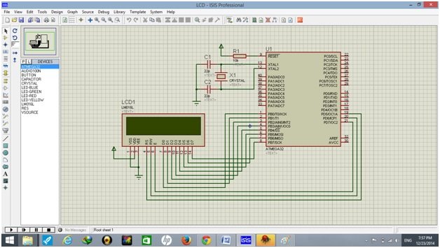
Schematic Diagram
We designed our circuit on Proteus. A circuit diagram of 16×2 LCD with Atmega32 microcontroller is given below:
Atmega32 LCD Interfacing Code
We use Atmel Studio 6 for the development of code, and the code is written in C.
#ifndef F_CPU
# define F_CPU 16000000 UL // clock speed is 16MHz
#endif

#include<avr/io.h> // AVR header
#include<util/delay.h> // delay header

//******************LCD PROGRAM STARTS*********************//

#define LCD_DATA PORTB // port B is selected as LCD data port
#define ctrl PORTD // port D is selected as LCD command port

#define en PD7 // enable signal is connected to port D pin 7
#define rw PD6 // read/write signal is connected to port D pin 6
#define rs PD5 // register select signal is connected to port D pin 5

void LCD_cmd(unsigned char cmd);
void init_LCD(void);
void LCD_write(unsigned char data);

int main(void)
{
  DDRB = 0xFF; // set LCD data port as output
  DDRD = 0xE0; // set LCD signals (RS, RW, E) as out put

  init_LCD(); // initialize LCD
  _delay_ms(100); // delay of 100 Milli seconds

  LCD_cmd(0x0C); // display on, cursor off
  _delay_ms(100);

  LCD_write(' '); // call a function to display space on LCD
  _delay_ms(1);

  LCD_write(' '); // call a function to display space on LCD
  _delay_ms(1);

  LCD_write(' '); // call a function to display space on LCD
  _delay_ms(1);

  LCD_write(' '); // call a function to display space on LCD
  _delay_ms(1);

  LCD_write(' '); // call a function to display space on LCD
  _delay_ms(1);

  LCD_write('A'); // call a function to display "A" on LCD
  _delay_ms(100);

  LCD_write('V'); // call a function to display "V" on LCD
  _delay_ms(100);

  LCD_write('R'); // call a function to display "R" on LCD
  _delay_ms(100);

  LCD_cmd(0xC0); // move cursor to the start of 2nd line
  _delay_ms(100);

  LCD_cmd(0x0C); // display on, cursor off
  _delay_ms(100);

  LCD_write(' '); // call a function to display space on LCD
  _delay_ms(1);

  LCD_write(' ');
  _delay_ms(1);

  LCD_write(' ');
  _delay_ms(1);

  LCD_write('A'); // call a function to display "A" on LCD
  _delay_ms(100);

  LCD_write('t'); // call a function to display "t" on LCD
  _delay_ms(100);

  LCD_write('m'); // call a function to display "m" on LCD
  _delay_ms(100);

  LCD_write('e'); // call a function to display "e" on LCD
  _delay_ms(100);

  LCD_write('g'); // call a function to display "g" on LCD
  _delay_ms(100);

  LCD_write('a'); // call a function to display "a" on LCD
  _delay_ms(100);

  LCD_write('3'); // call a function to display "3" on LCD
  _delay_ms(100);

  LCD_write('2'); // call a function to display "2" on LCD
  _delay_ms(100);

  LCD_cmd(0x0E); // make display ON, cursor ON
  _delay_ms(1);

  return 0;
}

void init_LCD(void)
{
  LCD_cmd(0x38); // initialization in 8bit mode of 16X2 LCD
  _delay_ms(1);

  LCD_cmd(0x01); // make clear LCD
  _delay_ms(1);

  LCD_cmd(0x02); // return home
  _delay_ms(1);

  LCD_cmd(0x06); // make increment in cursor
  _delay_ms(1);

  LCD_cmd(0x80); // "8" go to first line and "0" is for 0th position
  _delay_ms(1);

  return;
}

//**************sending command on LCD***************//

void LCD_cmd(unsigned char cmd)
{
  LCD_DATA = cmd; // data lines are set to send command

  PORTD &= ~(1 << rs); // RS sets 0, for command data
  PORTD &= ~(1 << rw); // RW sets 0, to write data
  PORTD |= (1 << en); // make enable from high to low

  _delay_ms(100);
  PORTD &= ~(1 << en); // make enable low

  return;
}

//*****************write data on LCD*****************//

void LCD_write(unsigned char data)
{
  LCD_DATA = data; // data lines are set to send command
  PORTD |= (1 << rs); // RS sets 1, for command data
  PORTD &= ~(1 << rw); // RW sets 0, to write data
  PORTD |= (1 << en); // make enable from high to low

  _delay_ms(100);
  PORTD &= ~(1 << en); // make enable low

  return;
}
Code Explanation
In this section, we will discuss the workings of this code.
#ifndef F_CPU
# define F_CPU 16000000 UL // clock speed is 16 MHz
#endif

#include <avr/io.h> // AVR header
#include <util/delay.h> // delay header
Firstly, we define the clock of the ATmega32 microcontroller at 16 MHz. Next, we define the header tags <avr/io> and <util/delay>. The first tag helps us with the input and output of AVR microcontrollers. Whereas the seconds tag helps us to add delay without making a custom function in the program.
Declaring LCD ports, pins and functions
//******************LCD PROGRAM STARTS*********************//

#define LCD_DATA PORTB // port B is selected as LCD data port
#define ctrl PORTD // port D is selected as LCD command port

#define en PD7 // enable signal is connected to port D pin 7
#define rw PD6 // read/write signal is connected to port D pin 6
#define rs PD5 // register select signal is connected to port D pin 5

void LCD_cmd(unsigned char cmd);
void init_LCD(void);
void LCD_write(unsigned char data);
Now, we declare port B as a data port and port D as a command port. Next, we define three higher pins of port D for the en, rw, and rs pins of the LCD Display. Lastly, we declare the LCD command, LCD initialize, and LCD write functions.
Main function
int main(void)
{
  DDRB = 0xFF; // set LCD data port as output
  DDRD = 0xE0; // set LCD signals (RS, RW, E) as out put

  init_LCD(); // initialize LCD
  _delay_ms(100); // delay of 100 Milli seconds

  LCD_cmd(0x0C); // display on, cursor off
  _delay_ms(100);

  LCD_write(' '); // call a function to display space on LCD
  _delay_ms(1);

  LCD_write(' '); // call a function to display space on LCD
  _delay_ms(1);

  LCD_write(' '); // call a function to display space on LCD
  _delay_ms(1);

  LCD_write(' '); // call a function to display space on LCD
  _delay_ms(1);

  LCD_write(' '); // call a function to display space on LCD
  _delay_ms(1);

  LCD_write('A'); // call a function to display "A" on LCD
  _delay_ms(100);

  LCD_write('V'); // call a function to display "V" on LCD
  _delay_ms(100);

  LCD_write('R'); // call a function to display "R" on LCD
  _delay_ms(100);

  LCD_cmd(0xC0); // move cursor to the start of 2nd line
  _delay_ms(100);

  LCD_cmd(0x0C); // display on, cursor off
  _delay_ms(100);

  LCD_write(' '); // call a function to display space on LCD
  _delay_ms(1);

  LCD_write(' ');
  _delay_ms(1);

  LCD_write(' ');
  _delay_ms(1);

  LCD_write('A'); // call a function to display "A" on LCD
  _delay_ms(100);

  LCD_write('t'); // call a function to display "t" on LCD
  _delay_ms(100);

  LCD_write('m'); // call a function to display "m" on LCD
  _delay_ms(100);

  LCD_write('e'); // call a function to display "e" on LCD
  _delay_ms(100);

  LCD_write('g'); // call a function to display "g" on LCD
  _delay_ms(100);

  LCD_write('a'); // call a function to display "a" on LCD
  _delay_ms(100);

  LCD_write('3'); // call a function to display "3" on LCD
  _delay_ms(100);

  LCD_write('2'); // call a function to display "2" on LCD
  _delay_ms(100);

  LCD_cmd(0x0E); // make display ON, cursor ON
  _delay_ms(1);

  return 0;
}
In the main function, first we set the data and command ports as output. Then we call the init_LCD() and LCD_cmd() functions with a delay of 100 ms. This command function turns the cursor off. After this, we print “AVR” in the middle of the first line, and by using LCD_cmd, we move to the second row. After moving to the second row, we print “Atmega32” in the middle of this row. At last, by using LCD_cmd (0x0E), we turn on the display and the cursor.
LCD Initializing Function
void init_LCD(void)
{
  LCD_cmd(0x38); // initialization in 8bit mode of 16X2 LCD
  _delay_ms(1);

  LCD_cmd(0x01); // make clear LCD
  _delay_ms(1);

  LCD_cmd(0x02); // return home
  _delay_ms(1);

  LCD_cmd(0x06); // make increment in cursor
  _delay_ms(1);

  LCD_cmd(0x80); // go to first line and "0" is for 0th position
  _delay_ms(1);

  return;
}
The init_LCD function initializes the LCD display. Firstly, we set the 8-bit mode for data transfer. Then we return the displays cursor to the home or starting position. The LCD_cmd(0x06) command sets the increment mode, which means the Display will increment to the next position after printing a character. Lastly, we move the cursor to the first position of the display and return to the function.
LCD command function
//**************sending command on LCD***************//

void LCD_cmd(unsigned char cmd)
{
  LCD_DATA = cmd; // data lines are set to send command

  PORTD &= ~(1 << rs); // RS sets 0, for command data
  PORTD &= ~(1 << rw); // RW sets 0, write data
  PORTD |= (1 << en); // make enable high, triggering pulse from high to low

  _delay_ms(100);
  PORTD &= ~(1 << en); // make enable low

  return;
}
In the LCD_cmd function body, first we set data lines to send commands. Next, we set the rs and rw pins to low and the en pin to high. After about 100 ms, we turn the en pin to low and return from the function.
LCD character function
//*****************write data on LCD*****************//

void LCD_write(unsigned char data)
{
  LCD_DATA = data; // data lines are set to send command
  PORTD |= (1 << rs); // RS sets 1, for character data
  PORTD &= ~(1 << rw); // RW sets 0, write data
  PORTD |= (1 << en); // make enable high triggering pulse from high to low

  _delay_ms(100);
  PORTD &= ~(1 << en); // make enable low

  return;
}
Now, in the function body, we first set the data lines to command. Then we set the RS to high and turn the RW to low. Next, we set the en pin high, and with a delay of 100 ms, we turn this pin low. Lastly, we return from this function.
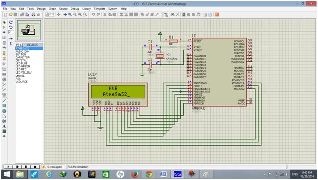
Simulation on Proteus
Compile the above code and dump the HEX file into the AVR microcontroller as described in the previous tutorials. Make the necessary settings and check the display on the LCD.
Basic Commands used in LCD Display
| COMMANDS | DESCRIPTION |
|---|---|
| 0x01 | Clear screen |
| 0x02 | return home |
| 0x04 | Cursor decrement |
| 0x05 | Display shifts to right |
| 0x06 | Cursor increment |
| 0x07 | Display shifts to left |
| 0x08 | Cursor and display OFF |
| 0x10 | Cursor position Shifts to left |
| 0x14 | Cursor position shifts to right |
| 0x38 | Using two lines, 8-bit mode |
| 0x28 | Using two lines, 4-bit mode |
| 0x80 | Move cursor to the beginning of first line |
| 0x0C | Display ON, cursor OFF |
| 0XC0 | Move cursor to the beginning of second line |
| 0x0A | Display OFF, cursor ON |
| 0x0E | Display ON, cursor blinking |
| 0x30 | For display in one line in 8-bit mode |
| 0x20 | For display in one line in 4-bit mode |
| 0x0F | Display data on cursor blinking |
| 0x18 | Shift complete data to left side |
| 0x1C | Shift complete data to right side |
Conclusion
In this tutorial, we have covered the following topics:
- What is LCD.
- Pin description and programming of the LCD.
- Schematic diagram.
- Code with an explanation.
- Proteus simulation
Related Articles
You may also like to read:
- I2C LCD interfacing with ESP32 and ESP8266 in Arduino IDE
- I2C LCD with STM32 Blue Pill using STM32CubeIDE
- ESP32 with MPU6050 Accelerometer, Gyroscope, and Temperature Sensor ( Arduino IDE)
- DC motor interfacing with atmega32 and L293
- Displaying Images in ESP32 and ESP8266 Web Server
- STM32 Blue Pill with 4-Digit 7 Segment Display using STM32CubeIDE
This is all for this article. Thanks for visiting our website. Keep sharing and keep learning 🙂
write a program in AVR LCD, take input from keypad and perform addition and subtraction .Results with digits added or subtracted must be displayed on LCD.
i am getting error on lcd_write() like stray ‘ 221’ in program
thank you
Great explanation but there is a line I don’t get (LCD_DATA= data;) What is LCD_DATA ?!!
Thank you very much; I am glad I reach on this blog after many hours find a way I can accomplish this task. I am really gratefully.