In this tutorial, we will learn to use EL357 optocoupler IC Compact 4 Pin SOP IC. It is a phototransistor and LED based photocoupler which provides high voltage isolation between input and output sources. The isolation voltage can be upto 3750 volts RMS value.
Photocoupler Introduction
Optocoupler is an electronic device that transfers electrical signals between two electrically isolated circuits. It is also known as Opto-Isolator, Photo Coupler, or optical isolator. There are many different kinds of optocoupler available; which are designed according to different needs and switching capabilities. Few categories are given below.
- PhotoTransistor
- Photo Darlington Transistor
- Opto TRIAC
- Photo SCR
Optocoupler is used to protect sensitive circuits. It enables us to design many hardware circuits of daily use. It avoids the need of replacing components by protecting them. In this article, we are concerned about the EL357 optocoupler and it belongs to the first category.
EL357 Introduction
It is a low voltage infrared LED input and phototransistor output based isolator. If you do not find a PC817 optocoupler, you can use EL357 exact replacement for PC817. In terms of internal structure, EL357 consists of one infrared LED and one NPN phototransistor. When we apply a 5-volt signal to an infrared LED, it emits an infrared light, when this emitted light falls on the base terminal of a simple transistor, it turns on. In this way, we can pass low voltage signals to a high voltage circuit.
EL357 Pinout
The figure given below shows the pin configuration diagram of EL357 IC.

Pin Configuration Details
This IC consists of 4 pins and the detail of each pin is as follows.
- Pin1 : Anode pin of the infrared LED.
- Pin2 : Cathode pin of the infrared LED.
- Pin3 : Emitter pin of the NPN phototransistor.
- Pin4 : Collector pin of the NPN phototransistor.
EL357 Series
The ordering code of this IC is as follows.
EL357(X)(Y)-V
X represents the Current Transfer Ratio with the following options.
- None = 50 to 600 %
- A = 80 to 160 %
- B = 130 to 260 %
- C = 200 to 400 %
- D = 300 to 600 %
Y represents either it is in Tape or Real packaging.
V represents that either it is approved by VDE or not.
Below is a schematic figure of the IC.

Features
This IC has the following distinguishing features.
- Small outline compact package.
- Current transfer ratio is from 50 to 600% with IF = 5mA and VCE = 5V.
- The isolation voltage between output and input is very high. i.e. 3750V RMS value.
- Lead-free IC.
- Collector to emitter voltage is also high for this IC i.e. 80V
- Power dissipation of 200mW.
- Operating temperature range from -55 to 110 degrees centigrade.
- It can bear a soldering temperature up to 260 degrees centigrade.
How to use EL357
The below simulation figures show the basic working of EL357 IC.


Internal Schematic
This IC has two parts which are given below.
- Infrared LED
- Phototransistor
The positive terminal of the voltage source has been connected with the anode terminal of IR LED (Pin 1). The cathode terminal of IR LED (Pin 2) is fed with 0 potential i.e. – ve terminal of the voltage source.
The emitter terminal of the phototransistor (Pin 4) is fed with +ve potential through a resistor of 220 ohms to limit the current and the collector pin of the phototransistor (Pin 3) is fed with 0 potential through the LED (as output device).
How it Works?
The input at IR LED causes the emission of IR light, this light signal is detected by Phototransistor. On detection, the NPN type phototransistor enters in conduction mode and passes the +ve potential at the collector to the emitter terminal which turns ON the LED at the output.
It should be kept in mind that connecting the 0V(ground) potential of both input and output power supplies will simply bypass the purpose of the optocoupler. Although one may think the ground level of all voltage sources means the same thing but it is not the case. The ground level of the 220VAC source can be quite different as compared to the 5VDC voltage source. In this case, connecting the ground of both sources will be hazardous. Even if 220VAC has been converted into a 5VDC voltage source still it is recommended that connecting ground of both sources should be avoided.
Where to use EL357 and Example Circuits
In many communication circuits, the impedance matching among several components is necessary because in an ideal case, the energy of the signal coming out of a pin travels through traces of PCB and is completely absorbed by the load. However, if energy is not completely absorbed by the load, the remaining part of the energy will travel back to the pin and will alter the desired output. So optocoupler is used in such cases which transmit the signal without any need of impedance matching.
Zero Crossing Detection Circuit
In many applications, zero-crossing detection of AC source is used. The difference in angle of Real Power and Reactive Power is used in Power Factor Correction System. And this difference is measured by detecting the zero-crossing of voltage and current waves. Also, frequency testing circuits work on detecting zero crossings of source waveform. EL357 optocoupler can be used in sensing the zero crossings of source waveform. The response time of the EL357 optocoupler is in nanoseconds and it turns on and off very fast on zero crossings of any waveform. The figure below shows the zero frequency detector using the EL357 an optocoupler.

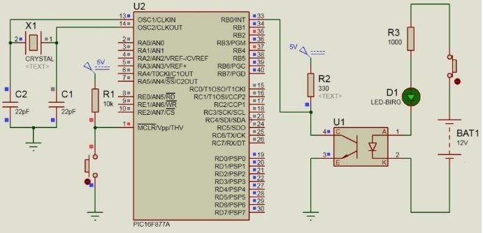
Microcontroller Interfacing
To safely read the logic level as Logic 0 and Logic 1 from a source, Optocoupler EL357 can be used. The voltage obtained from the transformerless power supply can contain noise, in case it is directly connected to the microcontroller can lead to malfunctioning of the microcontroller.
Also if the input pins of the microcontroller are directly exposed to electrical surge it can damage the input of the microcontroller so EL357 optocoupler is used between the input signal and microcontroller to avoid such damages.
The below figure shows the use of the EL357 Optocoupler for this purpose.
EL357 Applications
- Communication between high voltage and low voltage circuits.
- Used in industrial automation.
- DC to DC converters.
- Programmable controllers.
- System appliances and measuring instruments use this optocoupler.
- It is also used in home appliances for example fan heaters.
2D Diagram

Datasheet
Alternative Optocoupler
Related Articles:
Am I right, at “How to use EL357” section, from the two explaining schematics missing the current limiter resistor on the Input side?
Hi, Thanks for pointing out a correction. But the circuit given in this article is just for demo purpose only. For practical implementation we should use a current limiting resistor.