In this getting started tutorial, we will learn to interface the DRV8825 stepper motor driver module with Arduino. This DRV8825 driver module which is used to control a stepper motor in a relatively simple manner. Using only two pins of Arduino and DRV8825 driver module, we can control the speed of the rotation as well as the direction of rotation of a stepper motor. We will learn all about this driver module and how to use it with Arduino to control a bipolar NEMA 17 stepper motor. This guide also includes two Arduino sketches that provide a good basic understanding of how to easily control the speed, direction as well as acceleration/deceleration of the stepper motor using this stepper motor driver module.
We have similar guides with ESP32 and ESP8266 NodeMCU:
- Control Stepper Motor with DRV8825 Driver Module and ESP32
- Control Stepper Motor with DRV8825 Driver Module and ESP8266 NodeMCU
We will require the following components for this user guide:
Required Components
- Arduino
- DRV8825 Stepper Driver Module
- NEMA 17 Stepper Motor
- External 12V power supply
- Connecting Wires
Introducing Stepper Motors
Stepper motors are DC brushless and synchronous motors. They rotate in discrete steps of predefined values and are able to rotate both clockwise and anticlockwise. Unlike other DC motors, they provide a precise position control according to the number of steps per revolution for which the motor is designed. That means a complete revolution of a stepper motor is divided into a discrete number of steps. They are commonly used in CNC machines, Robotics, 2D and 3D printers.
For this guide, we will use a NEMA 17 stepper motor and control it through a DRV8825 Driver Module.
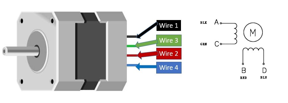
NEMA 17 Stepper Motor
It is suitable for 3d printers, CNC Machines, Engraving Machines, Robot Arms, etc. In low-speed devices which require smart rotatory movement at a specific speed without missing any single step can use the NEMA 17. NEMA 17 torque-speed is changeable by applying the different operating speeds. Actually, the torque depends on multiple factors, which are applying current, voltages and the third factor is the induction of coil within the motor. The rotation of the motor requires the magnetic field to make a single step. The time required to make the coil fully magnetic depends on the induction of the coil.
In NEMA 17 all pins are connected internally with the coil. To make the movement we need to magnetize the coil. Internally to control the stepper motor we will have to use the green and black pair. The second pair will be of red and blue.
Specifications
- Its rated voltage is 12V
- Phase current is 2.2A
- The Holding torque is equal to 40N.cm
- One step angle will be of 1.8 Deg.
- Total steps for each resolution will be 200.
- 4-wire and 8-inch lead
- Number of phases are 4
- Total inductance by each phase will be 2.8 mH
- The resistance of the coil is 1.5 Ohm per coil.
For more information about NEMA 17 refer to its datasheet here.
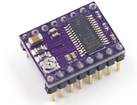
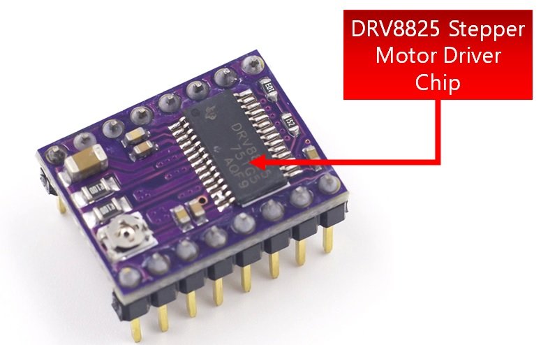
DRV8825 Stepper Motor Driver Module
The DRV8825 Driver Module is used to control the speed and direction of stepper motors mainly used in robotics, toys, CNC machines, and 3D printers for motion control. It is capable of operating bipolar stepper motors in full step, half step, quarter step, eighth step, and sixteenth step modes. There is a built-in translator which allows only two pins from the Arduino board to be used to control the speed and direction of the stepper motor.
This compact and small-sized driver module has the following specifications:
- Maximum Operating Voltage: 45V
- Maximum Current per phase is 2.2A so it can easily control NEMA17 that has an output current of 2A per phase.
- Dimensions: 15.5 × 20.5 mm (0.6″ × 0.8″)
- Capable of operating bipolar stepper motors in full step, half step, quarter step, eighth step, sixteenth step and thirty second step modes.
- In full step, the driver has 200 steps per revolution which is 1.8 degrees per step.
- Has thermal shutdown circuitry
The DRV8825 Driver Module comes with a heat sink to cool the inner circuity in case of higher power dissipation. It allows the IC to cool down if temperatures go higher than safe ones.

We can easily attach the heatsink on top of the DRV8825 IC as shown in the diagram above. This will protect the IC in case the temperature exceeds to a higher value. Thus, if you not attaching the heat sink then the driver module will allow 1.5A current per phase. However, with a cooling feature, the maximum allowed current per phase will be 2.2A instead. So it is always advisable to use the heatsink.
Pinout
The figure below shows the 16 pins that are present on the DRV8825 Driver Module:
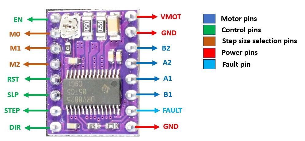
The module has a total of 16 pins which can be divided into four categories: the output pins in blue which will be connected with the motor, the control pins in green, the step size selection pins in brown, and the power pins in red.
Let us discuss them one by one.
Motor Pins
These are the motor coil pins connected to each of the four coils of the motor. These pins will be connected with bipolar stepper motors (8.2V-45V) where an output maximum current is 2.2A per coil. Hence each pin will be able to supply a max of 2.2A to each of the coils of the stepper motor.
- B2: This is connected with motor coil 2 second pin.
- A2: This is connected with motor coil 1 second pin.
- A1: This is connected with motor coil 1 first pin.
- B1: This is connected with motor coil 2 first pin.
Control Pins
These are the control pins which are used to control where EN, SLP, and RST control the power states and DIR and STEP control the input.
STEP: This is the pin which controls the rotation steps (micro steps) of the motor. It will be connected with a digital pin of the Arduino board. When a high signal will be passed to this pin, the motor will move by one step. The speed of the motor rotation will change according to how soon the signal of the pin goes high.
DIR: This is the pin which controls the direction of the rotation of the motor. This will also be connected to a digital pin of the Arduino. When a high signal is passed to this pin, the motor will rotate clockwise whereas if a low signal is provided instead, the motor will rotate in an anti-clockwise direction.
EN: This is the enable pin. It is used to turn the outputs of the module on or off. A high signal will disable the outputs. By default, the pin is at a low state.
RST: This is the reset pin. It sets the internal translator to a predefined Home state which is the position where the motor starts initially. This position will vary depending upon the microstep resolution. This is an active low input where a HIGH signal will enable the driver.
SLP: This is also an active low input pin which is used to reduce power consumption by setting the module to sleep mode when the motors are not in use. This is achieved by supplying a low signal to this pin.
Step Size Selection Pins
These three pins M0, M1, and M2 are used to select the microstep resolution from the given six options which this driver module supports. The table below shows the states required for each of these three pins to enable the appropriate microstep resolution.
| M0 | M1 | M2 | Microstep Resolution |
|---|---|---|---|
| LOW | LOW | LOW | Full Step |
| HIGH | LOW | LOW | 1/2 Step |
| LOW | HIGH | LOW | 1/4 Step |
| HIGH | HIGH | LOW | 1/8 Step |
| LOW | LOW | HIGH | 1/16 Step |
| HIGH | LOW | HIGH | 1/32 Step |
| LOW | HIGH | HIGH | 1/32 Step |
| HIGH | HIGH | HIGH | 1/32 Step |
Moreover, these three pins are connected internally with pull-down resistors so by default when un-connected the microstep resolution will be set as a full step.
Power Pins
Lastly, we will talk about the power pins that include VMOT, GND, and logic GND. As you may notice unlike other stepper motor drivers the DRV8825 has a single power supply connection only for the motor. The DRV8825 powers up using the voltage regulator present in the driver module.
- VMOT, GND: This is the stepper motor power supply pins. Connect 8.2-45V external power supply with VMOT and common ground.
- logic GND: Connect this GND pin with the Arduino GND.
Fault Pin
The DRV8825 motor driver module also features a FAULT pin. This is used for over-current protection. The pin goes in a LOW state disabling the driver due to over-current protection. What happens is that the FAULT pin which is shorted with the SLP pin when goes in a LOW state which means that the driver is disabled.
Interfacing DRV8825 with stepper motor and Arduino
To connect the Arduino with the stepper motor and driver we will use all the pins of the driver except for the enable pin and the microstep resolution selection pins.
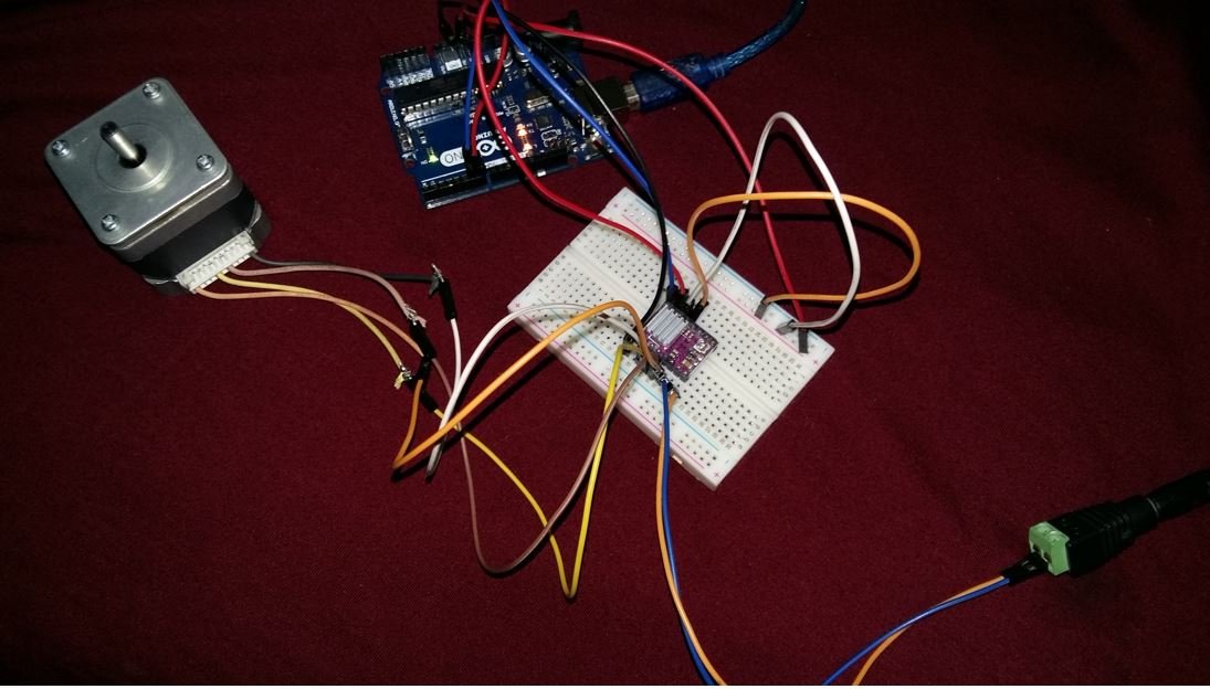
Follow the schematic diagram below to properly connect all the devices together.
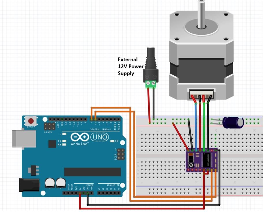
Connect the output pins of the driver with the respective motor pins. Connect the STEP pin and the DIR pin with any appropriate digital pin of the Arduino board. We have used digital pin 6 to connect with DIR and digital pin 7 to connect with STEP. As we want to operate our stepper mode in full mode hence we will leave the M0, M1, and M2 pins as they are. The RST pin and the SLP pin will be connected with 5V from Arduino so that the driver is enabled. Moreover, the logic GND pin will be connected with a GND pin from Arduino. The VMOT will be connected with an external power supply ranging between 8.5-45V. We are using a 12V external power supply. Make sure the GND pins are connected with the respective common grounds.
Additionally, we can also add a capacitor(minimum 100uF) with the external power supply connected with the stepper motor power supply pins to avoid voltage spike issues.
Current Limit
Before connecting the stepper motor with the driver module we have to make sure that the current running through the motor coils does not exceed the maximum rated current of the motor. To do that we will use the current limiting potentiometer featured on the DRV8825 motor driver as seen below:

We will require a multimeter. Connect the positive terminal of the multimeter with the potentiometer and the negative end of the multimeter with the GND of the driver module. The voltage measured at this point will be known as Vref. Adjust the potentiometer by turning it and the values for Vref will vary.
To set a current limit the following formula is used:
Current Limit = Vref x 2
Now set the Vref according to your motor’s rated current in order to ensure that the current is within the current limits of the motor.
Arduino Sketch Controlling NEMA 17 Stepper Motor with DRV8825 driver
Open your Arduino IDE and go to File > New. A new file will open. Copy the code given below in that file and save it.
This code will help us control the stepper motor using the DRV8825 driver’s DIR and STEP pins. We will show you how to rotate the motor in both directions at different speeds.
const int DIR = 6;
const int STEP = 7;
const int  steps_per_rev = 200;

void setup()
{
  Serial.begin(115200);
  pinMode(STEP, OUTPUT);
  pinMode(DIR, OUTPUT);
}
void loop()
{
  digitalWrite(DIR, HIGH);
  Serial.println("Spinning Clockwise...");

  for(int i = 0; i<steps_per_rev; i++)
  {
    digitalWrite(STEP, HIGH);
    delayMicroseconds(2000);
    digitalWrite(STEP, LOW);
    delayMicroseconds(2000);
  }
  delay(1000);

  digitalWrite(DIR, LOW);
  Serial.println("Spinning Anti-Clockwise...");

  for(int i = 0; i<steps_per_rev; i++)
  {
    digitalWrite(STEP, HIGH);
    delayMicroseconds(1000);
    digitalWrite(STEP, LOW);
    delayMicroseconds(1000);
  }
  delay(1000);
}
How the Code Works?
The first step is to define the digital pins of Arduino we have connected with the DIR and STEP pins of the driver. As you can see we have used the digital pins 6 and 7 to connect with DIR and STEP respectively. However, you can use any other suitable Arduino digital pins as well.
const int DIR = 6;
const int STEP = 7;
The next step is to define the steps per revolution. This is the number of steps our motor requires to move one complete revolution.
const int steps_per_rev = 200;Inside the setup() function, Serial.begin() is used to establish the serial connection between the development board at a baud rate of 115200. We will use the pinMode() function to configure the digital pins connected with STEP and DIR as output pins.
void setup()
{
  Serial.begin(115200);
  pinMode(STEP, OUTPUT);
  pinMode(DIR, OUTPUT);
}
loop()
Inside the loop() function we will first rotate the stepper motor in clockwise direction at a faster speed and then rotate it in the opposite direction at a slower speed. This will occur with a delay of 1 second.
To control the direction of the motor we will use the digitalWrite() function and pass the DIR pin as the first parameter and the state of the pin as the second parameter. To move the motor in the clockwise direction a high signal is passed to the DIR pin. Likewise, to move the motor in the anti-clockwise direction, a low signal is passed to the DIR pin. Additionally, the serial monitor will display the direction of the motion of the motor.
 digitalWrite(DIR, HIGH);
  Serial.println("Spinning Clockwise...");
To control the speed of the motor we will use a for loop till the steps per revolution and change the state of the STEP pin from HIGH to LOW with a delay in between. The faster the state of the STEP pin will be set to HIGH the faster the motor will spin. By increasing/decreasing the delay we are basically changing the frequency of the signal which then alters the speed of the motor.
void loop()
{
  digitalWrite(DIR, HIGH);
  Serial.println("Spinning Clockwise...");

  for(int i = 0; i<steps_per_rev; i++)
  {
    digitalWrite(STEP, HIGH);
    delayMicroseconds(2000);
    digitalWrite(STEP, LOW);
    delayMicroseconds(2000);
  }
  delay(1000);

  digitalWrite(DIR, LOW);
  Serial.println("Spinning Anti-Clockwise...");

  for(int i = 0; i<steps_per_rev; i++)
  {
    digitalWrite(STEP, HIGH);
    delayMicroseconds(1000);
    digitalWrite(STEP, LOW);
    delayMicroseconds(1000);
  }
  delay(1000);
}
Demonstration
Make sure you choose the correct board and COM port before uploading your code to the board. Go to Tools > Board and select Arduino UNO. Next, go to Tools > Port and select the appropriate port through which your board is connected.

Click on the upload button to upload the code into the board.
After you have uploaded your code to the development board, press its RST button.
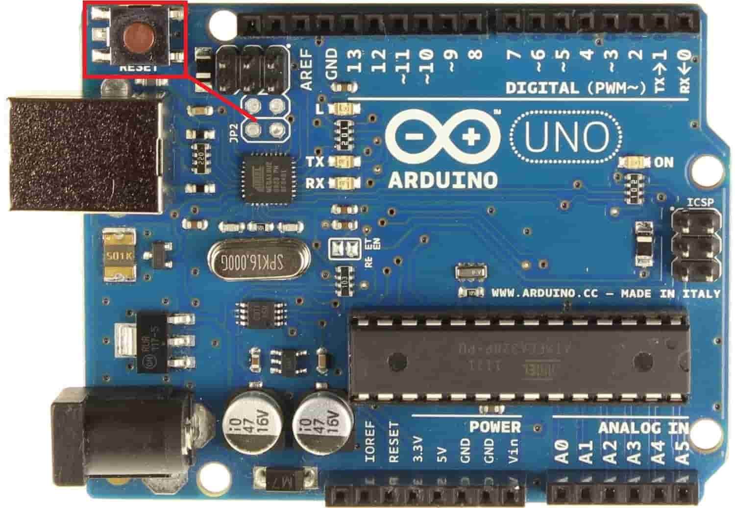
The stepper motor will start rotating clockwise and then anti-clockwise repeatedly.
In your Arduino IDE, open up the serial monitor and you will be able to see the status of the motor rotation as well.

Video demo:
Installing AccelStepper Library
We will require the AccelStepper library present in Arduino Library Manager to control more stepper motors as well as include acceleration/deceleration as well. This library will provide us with useful functions to set the maximum speed, acceleration, and steps per revolution to rotate the motor in both directions.
To install the library, we will use the Arduino Library Manager. Open your Arduino IDE and go to Sketch > Include Libraries > Manage Libraries. Type ‘Accelstepper’ in the search bar and install the latest version.

Arduino Sketch Controlling Stepper Motor
Open your Arduino IDE and go to File > New. A new file will open. Copy the code given below in that file and save it.
This code will help us control the stepper motor by setting the maximum speed, acceleration and steps per revolution. We will show you how to rotate the motor in both directions.
#include <AccelStepper.h>

const int DIR = 6;
const int STEP = 7;

#define motorInterfaceType 1
AccelStepper motor(motorInterfaceType, STEP, DIR);

void setup() {
  Serial.begin(115200);
  motor.setMaxSpeed(1000);
  motor.setAcceleration(50);
  motor.setSpeed(200);
  motor.moveTo(200);
}

void loop() {
  if (motor.distanceToGo() == 0) {
    motor.moveTo(-motor.currentPosition());
    Serial.println("Rotating Motor in opposite direction...");
  }
  motor.run();
}
How the Code Works?
Firstly, we will include the AccelStepper.h library. This library provides useful functions that make it easy to control the stepper motor using Arduino.
#include <AccelStepper.h>
The next step is to define the digital pins of Arduino we have connected with the DIR and STEP pins of the driver. As you can see we have used digital pins 6 and 7 to connect with DIR and STEP respectively.
const int DIR = 6;
const int STEP = 7;
Additionally, we will define the motor interface type as ‘1’. This means that we are using an external driver that consists of the STEP and DIR pins.
#define motorInterfaceType 1Now we will create an instance of the AccelStepper library called motor() and pass motorInterfaceType, STEP, and DIR as the three parameters inside it.
AccelStepper motor(motorInterfaceType, STEP, DIR);Inside the setup() function, Serial.begin() is used to establish the serial connection between the development board at a baud rate of 115200. We will use the setMaxSpeed() method on the motor instance and pass the speed of the motor as an argument inside it. In our case, we are setting the stepper motor speed to 1000. We will also set the acceleration of the motor using setAcceleration() and pass the acceleration in steps per second per second. The moveTo() method takes in the argument steps per revolution which is 200 as we are using NEMA 17. This will be used to mark our target position.
void setup() {
  Serial.begin(115200);
  motor.setMaxSpeed(1000);
  motor.setAcceleration(50);
  motor.setSpeed(200);
  motor.moveTo(200);
}
loop()
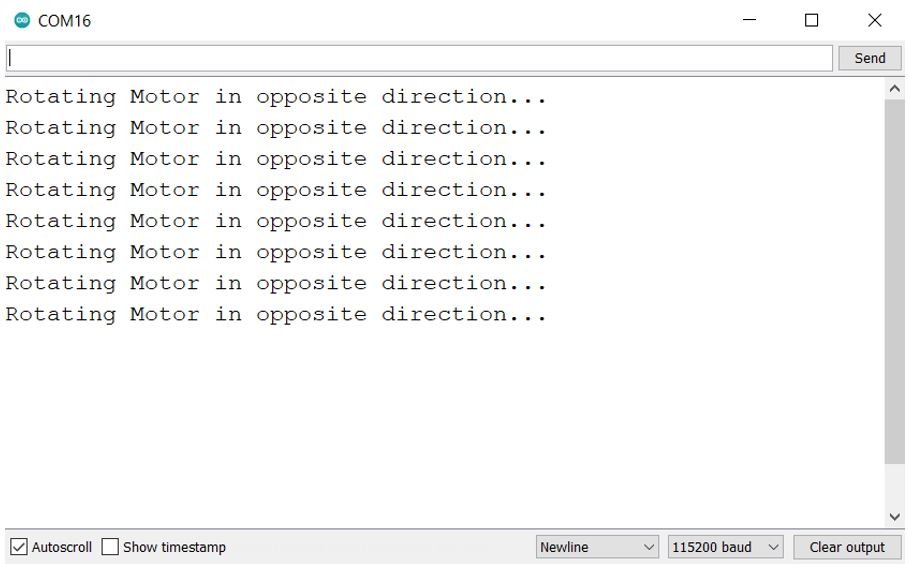
Inside the loop() function, we will rotate the motor in both directions. This will be achieved by keeping track of the target position. If the target position has been reached then another target position will be marked. This will be the same in value as before but with a negative sign. Thus, reversing the direction of the motor. Additionally, we will print when the motor changes direction in the serial monitor as well. The run() method will be responsible to rotate the motor every one step at a time.
void loop() {
  if (motor.distanceToGo() == 0) {
    motor.moveTo(-motor.currentPosition());
    Serial.println("Rotating Motor in opposite direction...");
  }
  motor.run();
}
Demonstration
Make sure you choose the correct board and COM port before uploading your code to the board. Go to Tools > Board and select Arduino UNO. Next, go to Tools > Port and select the appropriate port through which your board is connected.
Click on the upload button to upload the code into the board.
After you have uploaded your code to the development board, press its RST button.
The stepper motor will start rotating clockwise while accelerating until one revolution and then move anti-clockwise while decelerating and then stopping. Then the loop will start again.
In your Arduino IDE, open up the serial monitor and you will be able to see the status of the motor rotation as well.
Video Demo:
You may also like to read other stepper motor tutorials:
- Stepper Motor Control with L298N Motor Driver and Arduino
- Arduino L293D Motor Driver Shield Control DC, Servo, and Stepper Motors
- Stepper Motor Control with L293D Motor Driver IC and Arduino
- ESP8266 NodeMCU Stepper Motor WebSocket Web Server using Arduino IDE
- Stepper Motor Control with L298N Motor Driver and ESP32
- ESP32 Stepper Motor WebSocket Web Server using Arduino IDE
- Stepper Motor Control with L298N Motor Driver and ESP8266 NodeMCU