In this tutorial, we will learn how to control a stepper motor using the L298N Motor Driver with ESP8266 NodeMCU and Arduino IDE. This is a quick guide where we will learn how to interface an L298N motor driver with ESP8266 board and eventually learn how to control bipolar stepper motors in our case NEMA 17 with it. We will show you an Arduino sketch that will control the speed and direction of bipolar stepper motors (NEMA 17) every easily.
We have similar guides with ESP32 and Arduino:
- Stepper Motor Control with L298N Motor Driver and ESP32
- Stepper Motor Control with L298N Motor Driver and Arduino
Stepper Motors Introduction
Stepper motors are DC brushless and synchronous motors. They rotate in discrete steps of predefined values and are able to rotate both clockwise and anticlockwise. Unlike other DC motors, they provide a precise position control according to the number of steps per revolution for which the motor is designed. That means a complete one revolution of a stepper motor is divided into a discrete number of steps. They are commonly used in CNC machines, Robotics, 2D and 3D printers.
For this guide, we will use NEMA 17 stepper motor to demonstrate bipolar stepper motor control using the L298N motor driver module.
NEMA 17 Stepper Motor
NEMA 17 is a bipolar stepper motor rated at 12V with 200 steps per revolution and 60 rpm speed. In NEMA 17 all pins are connected internally with the coil. To make the movement we need to magnetize the coil. The rotation of the motor requires the magnetic field to make a single step. The time required to make the coil fully magnetic depends on the induction of the coil.
Internally to control the stepper motor we will have to use the green and black pair. The second pair will be of red and blue.
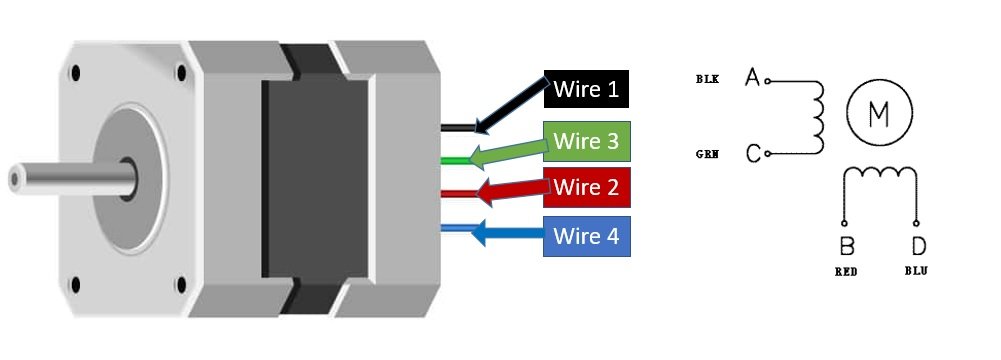
The table below shows the different ways to differentiate the wires for our stepper motor. This is important to know when connecting the stepper motor with the L298N Motor Driver outputs. You need to refer to the datasheet of your stepper motor to be sure as different manufacturers use different configurations.
| Pin No | Name | Name | Colour |
|---|---|---|---|
| 1 | A | A+ | Black |
| 2 | C | A- | Green |
| 3 | B | B+ | Red |
| 4 | D | B- | Blue |
Features:
- Its rated voltage is 12V
- Phase current is 2.2A
- The Holding torque is equal to 40N.cm
- One step angle will be of 1.8 Deg.
- Total steps for each resolution will be 200.
- 4-wire and 8-inch lead
- Number of phases are 4
- Total inductance by each phase will be 2.8 mH
- The resistance of the coil is 1.5 Ohm per coil.
L298N Motor Driver Module
The L298N motor driver module is very easy to use with microcontrollers and relatively inexpensive as well. It is widely used in controlling robots as we can connect up to four motors at once but if we want to control the speed and direction as well then it allows two dc motors or a single stepper motor to be connected. Thus, it is perfect for two-wheeled robots. This module is mainly used in robotics and in controlling dc and stepping motors.
The L298N motor driver module consists of an L298N motor driver IC, 78M05 5V regulator, 5V jumper enable, power LED, heat sink, resistors, and capacitors all combined in an integrated circuit. The diagram below shows all the components consisting inside the module.
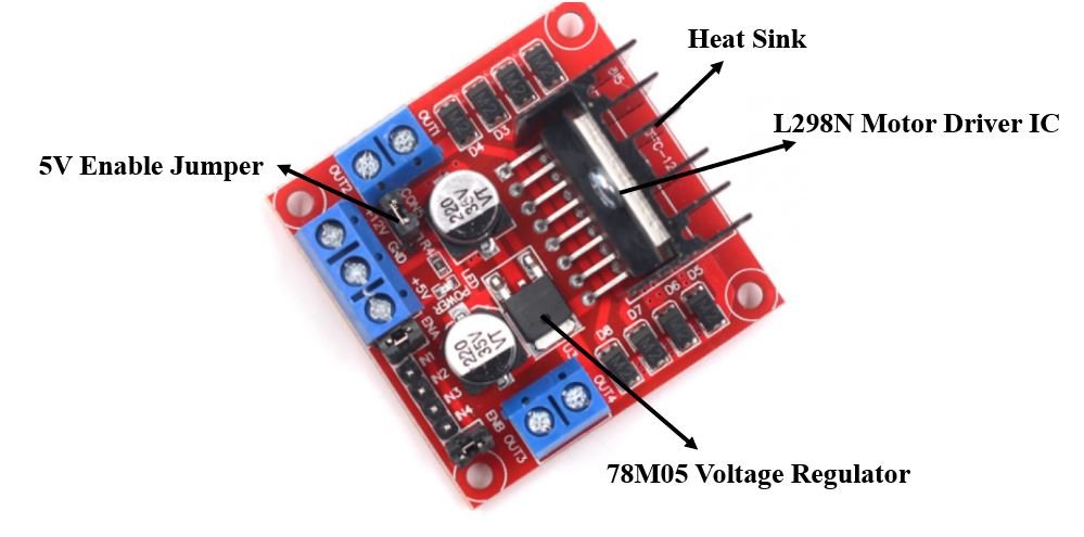
The L298N Motor driver IC is powerfully built with a big heat sink. It is a dual-channel H bridge motor driver which can be easily used to drive one single stepper motor.
The module also has a 78M05 5V regulator which is enabled through a jumper. Keeping the jumper intact, means the 5V regulator is enabled. If the motor power supply is less than 12V then we will power the module through the voltage regulator. The 5V pin in this case acts as an output to power the microcontroller. If the power supply is more than 12V, make sure the jumper is not intact and supply 5V power through the pin separately.
Note: If the jumper is connected, do not supply power to both the motor power supply input and the 5V power supply input.
Refer to the in-depth guide about the L298N motor driver with ESP32 by following this link.
Interface L298N DC Motor Driver with ESP8266 and NEMA 17 Stepper Motor
We will require the following equipment.
Required Equipment
- ESP8266 board
- L289N Motor driver Module
- NEMA 17 stepper motor
- External 12 V power supply
- Connecting Wires
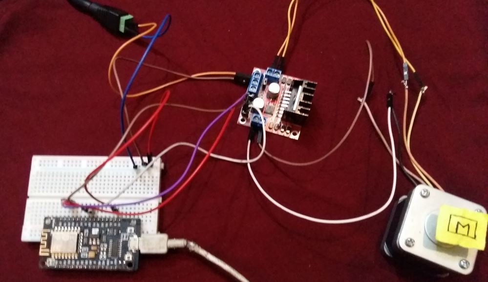
Assemble the circuit as shown in the connection diagram below.

For which ever stepper motor you are using refer to its datasheet to find the correct coloured wires to differentiate the A+, A-, B+ and B- wires. This will enable us to properly connect the motor with the OUT1, OUT2, OUT3 and OUT4 pins of the driver module. Connect the stepper motor’s coloured wires with correct output pins of the driver module. In our case, black wire is A+ and green wire is A- hence they will connect with OUT1 and OUT2 respectively. Likewise, the red wire is B+ and the blue wire is B- hence they will connect with OUT3 and OUT4 respectively.
Connect positive terminal of 12V power supply with 12V terminal and negative terminal of power supply with common ground.
We are keeping the 5V Enable jumper in its place as it will power up the L298N motor driver. Then, we have connected the input pins IN1, IN2, IN3 and IN4 with appropriate GPIO pins of ESP8266 board. We have used D1 (GPIO5), D2 (GPIO4), D5 (GPIO14) and D6 (GPIO12) respectively to connect with each of the input pins of the motor driver.
The enable pins ENA and ENB jumpers are not removed. This will ensure that the stepper motor stays enabled.
Arduino Sketch: Controlling Stepper Motor using L298N Motor Driver
Open your Arduino IDE and go to File > New. A new file will open. Copy the code given below in that file and save it.
This basic sketch will show us how to control a stepper motor’s speed and direction of rotation using the L298N motor driver.
#include <Stepper.h>

const int steps_per_rev = 200; //Set to 200 for NIMA 17
#define IN1 5
#define IN2 4
#define IN3 14
#define IN4 12

Stepper motor(steps_per_rev, IN1, IN2, IN3, IN4);


void setup()
{
  motor.setSpeed(60);
  Serial.begin(115200);
}

void loop()
{
  Serial.println("Rotating Clockwise...");
  motor.step(steps_per_rev);
  delay(500);

  Serial.println("Rotating Anti-clockwise...");
  motor.step(-steps_per_rev);
  delay(500);
}
How the Code Works?
Firstly, we will include the Stepper.h library. This library provides useful functions that make it easy to control the stepper motor.
#include <Stepper.h>The next step is to define the steps per revolution. This is the number of steps our motor requires to move one complete revolution. If using NEMA 17 set the value to 200. If using 28BYJ-48 instead set the value to 48.
const int steps_per_rev = 200; //Set to 200 for NIMA 17 and set to 48 for 28BYJ-48Next, we will define the input pins of the motor connections with the ESP9266 board. As you can see we have used the GPIO pins 5,4,14 and 12 to connect with IN1, IN2, IN3 and IN4 respectively. However, you can use any other suitable ESP8266 GPIO pins as well.
#define IN1 5
#define IN2 4
#define IN3 14
#define IN4 12
Now we will create an instance of the Stepper library called motor() and pass the steps per revolution and the individual motor input pins as arguments. Make sure you specify the input pins in their correct sequence. It is IN1, IN3, IN2, and IN4 for the stepper motor.
Stepper motor(steps_per_rev, IN1, IN2, IN3, IN4);
Inside the setup() function, Serial.begin() is used to establish the serial connection between the development board at a baud rate of 115200. We will use the setSpeed() method on the motor instance and pass the speed of the motor in rpm as an argument inside it. In our case we are setting the stepper motor speed to 60 revolutions per minute.
void setup()
{
  motor.setSpeed(60);
  Serial.begin(115200);
}
loop()
Inside the loop() function, we will first rotate the motor clockwise by using the step() method and passing the steps per revolution as the argument inside it. Hence the motor will rotate at steps of 200 per revolution. Likewise, to rotate the motor anti-clockwise we will pass the steps per revolution with a negative sign inside the step() method. Between the two types of rotations we will have a delay of 0.5 second. Additionally, we will print the type of rotation in the serial monitor as well.
void loop()
{
  Serial.println("Rotating Clockwise...");
  motor.step(steps_per_rev);
  delay(500);

  Serial.println("Rotating Anti-clockwise...");
  motor.step(-steps_per_rev);
  delay(500);
}
Demonstration
To see the demonstration of the above code, upload the code to ESP8266. Before uploading the code, make sure to select NodeMCU 1.0 from Tools > Board.

Also, select the correct COM port to which the board is connected from Tools > Port.
Once the code is uploaded to your board, the motor will start rotating.
The stepper motor will start rotating clockwise and then anti-clockwise repeatedly.
In your Arduino IDE, open up the serial monitor and you will be able to see the status of the motor rotation as well.

Further Projects:
You may also like to read these projects where we have learned to control stepper motor from a web server.
- ESP32 Stepper Motor WebSocket Web Server using Arduino IDE
- ESP8266 NodeMCU Stepper Motor WebSocket Web Server using Arduino IDE
You may also like to read other stepper motor tutorials:
- ESP8266 NodeMCU with Stepper Motor (28BYJ-48 and ULN2003 Motor Driver)
- ESP32 Interface with Stepper Motor (28BYJ-48 and ULN2003 Motor Driver)
- Stepper Motor Interfacing with TM4C123 Tiva Launchpad
- STEPPER MOTOR INTERFACING WITH 8051 MICROCONTROLLER
For more L298N Motor Driver articles:
How is this bipolar motor considered 4-phase in the features list?
When I do this, the red led on the L298N starts blinking. What did I do wrong?