This tutorial is about dc motor speed control with a pic microcontroller using the PWM method. There are many applications of DC motors, where we need a variable speed of DC motor. For example, it has applications in electric cars, trucks, and aircraft. These are three examples where we need variable speed. Although nowadays AC motors have more use in the market for variable speed applications over DC motor due to enhancement in power electronics and solid-state electronics. But, direct current rotational machines are still used today in many applications for variable speed requirements.
Types of DC motors
According to armature and field current circuit configuration, there are five types of DC motor:
- DC motor with separate excitation
- Shunt Type
- Series
- Compound ( Series+shunt)
- With excitation from a permanent magnet
The speed of separately excited DC motor and DC shunt motor can be made variable by changing terminal voltage and by changing the armature resistance. The speed of the DC series motor and permanent magnet DC motor can only be changed by changing the armature terminal voltage. Conversely, the Compound DC motor has both characteristics of DC series motor and DC shunt motor.
How to Control DC Motor Speed?
First of all, there is one features common in all types of DC motors. The rate of acceleration depends on the magnitude of the armature terminal voltage. Therefore, We can use this common feature to control speed. Speed control by changing armature terminal voltage is the same in all types of DC motors. In short, we can apply the same method to all direct current rotational machines.
At the start, to make this project possible, we have to learn a method through which we can apply variable DC voltage to the armature of any DC motor. Thereafter, we can control the speed of DC motor according to our requirements.
Methods to generate a variable armature voltage
We can generate variable dc voltage by two methods. Firstly, we will discuss the variable power supply method. After that, we will briefly go through the pulse width modulation technique.
Variable Power Supply Method
In variable power supply technique, there are some limitations. But we can still use it for small power DC motors. It can be controlled by making a variable power supply with the help of voltage regulators. They are capable to generate variable voltage within a specified limit provided by the manufacturer. There are many voltage regulators in the market. But there will be an issue of the current rating of DC motor. Because power supplies that make with such voltage regulators have not too much high power handling capability. A power supply is the main source of power to DC motor. Therefore this method is not practically feasible and recommended. This technique is costly also.
Pulse Width Modulation Technique
On the contrary, pulse width modulation is the best method to control DC voltage applied to the terminal of the armature. In pulse width modulation, we actually control the switching duty cycle, which is the ratio of on-time to the total time of switching.
PWM for DC Motor Speed Control
PWM Introduction
This is a method to control the output voltage with constant frequency switching and by adjusting on the duration of switching and in other words by changing the duty cycle of switching.
Constant switching time period = on time + off time
Duty Cycle = (on time / on time + off time ) %
The duty cycle can not be greater than 1 or 100%. Because on time will always be less than the total time period of switching frequency. The relationship of input-output voltage and the duty cycle is
output voltage = duty cycle * input voltage
Hence the output voltage and duty cycle is directly related to each other. However, their output also depends on switching frequency of switch. What is a switch here. I will discuss it later.
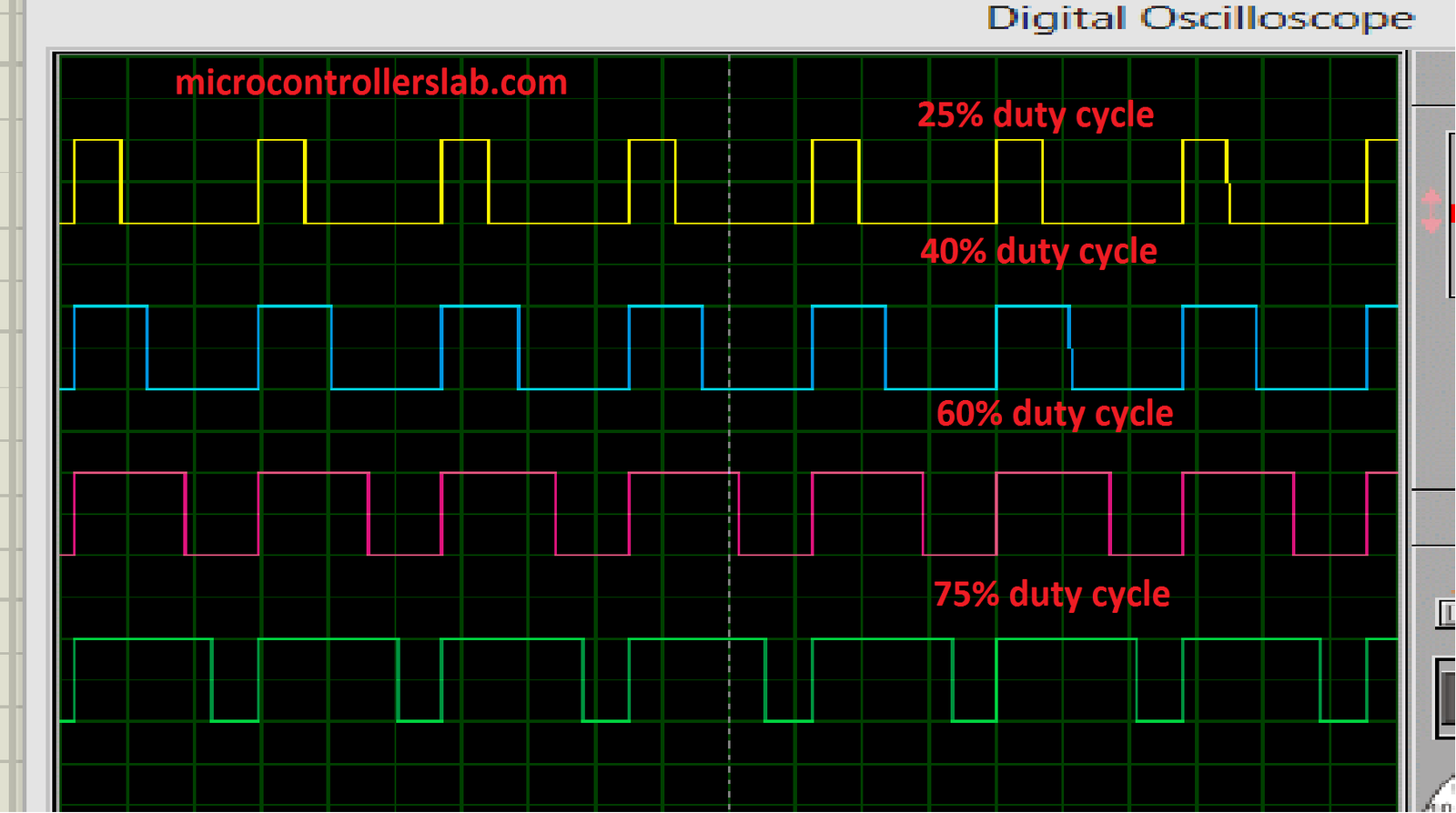
In the above picture, there are four PWM having different duty cycles. Therefore, we need to change the duty cycle according to the requirement of the output voltage. But output voltage can never be greater than the input voltage. At last, if you have still trouble in grasping these concepts, read this complete guide:
PWM Generation Methods
But now the question which must come into mind. How to generate PWM and how to use PWM for variable output voltage generation? At the present time, there are two ways to generate pulse width modulation with variable duty cycle:
- Using analog electronics ( operational amplifier, comparator and sawtooth wave, etc)
- Using digital electronics ( microcontrollers and dedicated PWM controllers IC’s )
We will not discuss the first method in this article. but in future, we will write a complete post on Pulse width modulator using analog electronics. But those who don’t know about programming and microcontrollers can use analog electronics methods for this purpose.
Dc Motor Speed Control using pic microcontroller
To control DC motor speed with PIC microcontroller, we should know about these two features:
- how to generate PWM using PIC microcontroller
- how to use the analog channel of PIC microcontroller to read analog voltage.
If you don’t know about these topics. Kindly visit the following link to get the understanding of PIC microcontrollers and PWM programming.
As we mentioned earlier, there are two methods to make a pulse width modulator. These are the analog Electronics method and the digital Electronics method using Microcontrollers.
Dedicated PWM controller ICs for Speed control
There are dedicated PWM controller IC’s are also available in the market like SG3525, UC3842, SG2525, and many others. These PWM controller IC’s also use analog electronics methods. Because their internal circuitry consists of operational amplifiers, resistors, and capacitors. I will write also write an article on PWM controllers for those who hate programming and don’t know about the use of Microcontrollers. But there are few issues with these ready to use PWM controller IC’s. A most important issue is:
- you will require many extra components to make them ready to use.
- The exact frequency is not achievable. 1-2% error
- There is also a frequency limitation which in some cases generates audible in motors.
But there are no such issues with pulse-width modulators of digital electronics type.
DC Motor Speed Control Circuit diagram
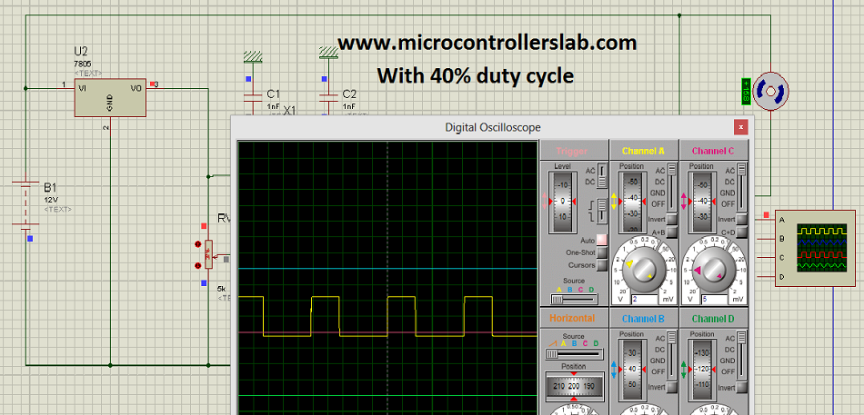
We have used PIC16F876 microcontroller to generate PWM and to change the duty cycle by reading the analog value of voltage across the variable resistor. we can use any microcontroller you want. But logic will remain the same.

In the above circuit diagram, 12v is used as a power source.7805 voltage regulator is used to provide 5 volts to variable resistor and supply to microcontroller. There is no need to give supply 5 volts in Proteus to a microcontroller. Because by default 5 volt and ground have been supplied to the microcontroller in Proteus. A variable resistor is used to change the duty cycle of PWM. By moving the knob of a variable resistor you can change the duty cycle which is directly related to the speed of the DC motor. Therefore, we can adjust the speed of the DC motor by adjusting the variable resistor knob according to your speed requirement.
Components List
- 7805 voltage regulator
- resistors
- PIC16F876 MICROCONTROLLER
- IRL1004 FET
- UF4007 DIODE
- 10MHZ CRYSTAL
- 1K Variable resistor
- 22pF capacitors
Video Lecture Demonstration
The PWM frequency is about 8Khz which will not make any audible noise. You can adjust it according to your motor specifications. IRL1004 is used as a switch. IRL1004 FET requires the only 5-volt logic level driver to operate FET and a negligible amount of current. Therefore there is no need for any driver to drive IRL1004 FET. It can handle more than one-ampere current very easily as it is mentioned in its datasheet. Diode 1N4007 is used as a freewheeling fast recovery diode. Because the motor is an inductive load and its back emf may damage the circuit. Freewheel diode will provide flow path to back emf current and avoid sparking across motor terminals.
Other DC Motor Projects
- PIC to PIC SPI communication with DC motor control
- Bluetooth based dc motor speed and direction control using Arduino
Code for speed control of dc motor
long ADCValue=0;
long ADCValueOld=1;

#byte portA = 0X05
#byte portB = 0X06
#byte portC = 0X07

void main()
{
set_tris_A(0b00101011);
set_tris_B(0b00000001);
set_tris_C(0b00000000);

portA=0X00;
portB=0X00;
portC=0X00;

setup_adc_ports(ALL_ANALOG);
setup_adc(ADC_CLOCK_INTERNAL);
setup_spi(FALSE);
setup_counters(RTCC_INTERNAL,WDT_288MS);
setup_timer_1(T1_INTERNAL|T1_DIV_BY_1);
setup_timer_2(T2_DIV_BY_1,255,1);
setup_ccp1(CCP_OFF);
setup_ccp2(CCP_PWM);
enable_interrupts(global);

set_adc_channel(0);
delay_us(10);

while(1)
{
ADCValue = Read_ADC();
delay_ms(100); // monitor 10 times a second

if ( ADCValue != ADCValueOld )
{
set_pwm2_duty(ADCValue);
ADCValueOld = ADCValue;
}
}
}
If you want to learn to program of PWM and ADC (analog to digital converter) using PIC Microcontrollers. Check PIC microcontroller tutorials.
If you want complete simulation and code of this project. Comment on this post with your email address and if you have any issue while making this project, feel free to comment on this post.
Future Recommendations
- Feedback control mechanism to ensure constant speed
- Direction control of DC motor using H bridge
- Try to control more than one motor.
- Final year projects: Speed control of DC motor through wireless communication like GSM, GPRS, Bluetooth, ZigBee, and many other wireless communication techniques.
I like your tutorial, please could you send me the code?
Hi .. I want to dim AC bulb with TRIAC can you please help me …
my mail id namratha.70@gmail.com
please send me the project files at following email adress
wajeeulhassan_92@yahoo.com
thnx
I am very much interested about your project. Please send me this project details & also source code. I am new in microcontroller.
Hi Bilal, can you please send me the full project simulation and the source code, very much interested.
Thank you
tebomaleka@gmail.com
Please provide me the simulation file of proteus & source code with hex code.
Please i need the simulation file & the code .
adityaingawale11@gmail.com
Hi i am Daniel. I am studying mechatronics final year and i looking for project ideas.
tayeterefe44@gmail.com. interesting so pls give me a simulation and code
send me the simulation and source code to my mail
ahmadzeb676@gmail.com
ahmadzeb676@gmail.com
i am very much intrested in this project. kindlysendme the code and simulations plz.. its urgent.. i will be thankful.
Mention your email address
plz how can I use this to control brushless through the 30-60amp.
plz friend don’t leave me a shame I’am waiting “facebook:Bashir Abdullah AK” & “twitter:Bashir Abdullah AK@Engr_BAAK”
thanks!!!!
Pls thanks for the tutorials can you do me the favor of sending the code to ikechi_19@yahoo.co.uk
Please send me the code comradedouglas.da@gmail.com
I want to know how to make it on proteus 8
please send me the project files at following email adress
sherifyoussef93@gmail.com
proteus and the code
please
raouhi.saad@gmail.com pls send me the code and the simulation
i love this tutorial and this particular topic was given to me design and construction of microcontroller based speed of a DC motor. so I just want to ask if I can get the complete write up and guide
pls. I want the complete stimulation and code on this project help me to send it to my email akin4luv@ymail.com
I am interested about this project, can you the project docs to my email id: purnakrishna.kallepalli@gmail.com
pls I need the simulation file and the code help me pls my email
elec.eng.moemen@gmail.com
Salam, thanx to send me the project files at following email adress:
dahwathis@yahoo.fr
hello,
i am very interrested in this project as i am working on the same topic, DC motor speed control with thyristors interfacing circuit.
i would like to receive the project files for this application.
here is my mail adress: fz.elasri@gmail.com
thank you for your help
Pls i want the complete code for this project. email me on wolex771@GMAIL
May I have the complete project please mczaloda@gmail.com
I want the complete stimulation and code on this project please help me by sending it to my email
Hello, I am interested in this project. Please email me the complete code for this project. Thank you.
wendy.goh1696@gmail.com
Hi…I am interested in your project…please I’d like to see the codes…my email is lavick3@gmail.com Thanks
Hi i’m interested in your project. Please email me the codes. My email me fatin.nazila@gmail.com. Thank you.
Hi im interested. Email me the code and simulation please? victorklaaste16@gmail.com Thank you.
I would really like to simulate your code. Please send it to melaniegerke@gmail.com
It was a great experience to see this tutorial , please email me the code of this project . I will be so grateful to you .
can you please send me the code. thank you so much . iamrodsaz@gmail.com
Hi Bilal. can you please send me the code. thank you so much . iamrodsaz@gmail.com
hi i would like the code and si,ulation for this project.
ibtisamiqbal@gmail.com
Hi Bilal ,
tutorial based on controlling dc motor speed woth pic was quiet interesting.
can u please send a code as i need this concept for my mini project.
Hi bilal, can you please send me the code. Thank you soo much
kazam1920@gmail.com
Hello Sir,
Thank you for this tutorial. I hope it will help me a lot to understand the speed control technique of dc motor. Sir I want to control the speed of 220V DC Shunt motor using same technique. So can you please me what all the changes I need to make in the circuit as well as the code for the microcontroller. Thank you so much in advance. Hope to hear soon from you.
Hello Sir,
I would like to know if the code is available for Download.
Thanks you 🙂
Hi Bilal,
Thank you for the Post/Please send me the code.
ie_engineering@outlook.com
Good post. please send the complete simulation and the codes via my e-mail: sijtade@gmail.com
i’m very intrested in ur project. plz brother can u send me the full symptoms of it.
khan.aizaz100@gmail.com
can i get the codes……..thanks sir
Thanks for the tutorial, if you please I need the protues file and the code,
Thanks
adeniyijamesa@gmail.com
plz i want the code zain aijaz hsmb786@gmail.com
contact me at microcontrollerslabhub@gmail.com
I am very interested to learn this .Please send me the complete details of this project.My mail id is elegantsaip1@gmail.com
hello Please give the full code and simulation
Thank you
hello Please give the full code and simulation
Thank you
I love this project, please can you send me this project please. My e-mail address is wilsonedafe1@gmail.com
hi please send me the code mewguv@gmail.com
hi please send me the code mewguv@gmail.com thanks
Hi,Thanks for your tutorial ,these are very helpful for power electronics students.Would you please provide me full code and simulation through this email bhuiyanmdhabib@gmail.com
Thanks
Habib
hello sir,i went to do a program for dc motor control by using ardiuno.so, please help me .how i can be done this program?
Hi, I really liked your tutorial. Can you please send me the simulation and code of this project at greatabhineet@gmail.com
Hi
Thank you for the Post/Please send me the code.
info.rkess@gmail.com
Wow great tutorial!!!
Do you mind to share and PM the code??? Currently I’m stuck at the code since there’s no input to AN0 from potentiometer. And my project got 2 potentiometer which is need to use AN0 and AN1, I’m using PIC16F877A
hello, C code and circuit diagram can you send?
think you
please send me the project files at following email adress
kyawmyo1183@gmail.com
please send me simulation and code .
nomansohaib1825@gmail.com
it was nice tutorial
Please send me code @ apte_aishwarya@yahoo.co.in
I like your tutorial, please could you send me the code?
Iranian.madar@gmail.com
Please, I want pic microcontroller software to control the speed of treadmill motor at constant speed
Hi
First of all, you need to figure out what kind of motor is used in a treadmill.
plz sent me complete file of this project on my email
I warmly welcome!
I am in the process of making PWM control of an electric motor for a 600W boat. I will ask for a code to program the PIC
Thank you
Hello, thanks for your interesting project. Please send me the full file and code of your project.
Kindly send me the whole simulation and code of this project
Hello, please send me the whole simulation and code files of this project.
Please provide me the simulation file of proteus & source code with hex code.
Please provide me the simulation file of proteus & source code with hex code.
it is good , please give me the codes and simulation.
Hello. I’m interested in the source code for this project. Thank you.
Please provide me the simulation file of proteus & source code with hex code.