LED drivers are essential components in the world of lighting, enabling the efficient and reliable operation of LED systems. In this article, we will delve into the world of LED drivers, exploring their purpose, applications, and the various configurations in which LEDs can be arranged. With a specific focus on the series configuration, we will explore a practical example of an LED driver using the UC3842 current mode controller IC. By understanding the fundamentals of LED drivers and their role in powering LED systems, we can unlock the full potential of modern lighting technology and create impactful lighting solutions.
UC3842 Introduction
The UC3842 is a popular current mode controller IC commonly used in LED driver circuits. It is a versatile and efficient controller that allows for accurate current regulation and control. In LED driver circuits, the UC3842 helps ensure that the LEDs receive a constant and regulated current, which is essential for their optimal performance and longevity.
By utilizing the features and capabilities of the UC3842, LED drivers can be designed to provide stable and efficient power to the LEDs. The UC3842 operates by comparing a voltage feedback signal from the LED string with a reference voltage inside the IC. It then adjusts the duty cycle of the PWM (Pulse Width Modulation) signal to maintain a constant current output.
The UC3842 can be configured to operate in different modes, including continuous conduction mode (CCM) and discontinuous conduction mode (DCM), depending on the specific requirements of the LED driver circuit. It also offers various protection features such as overcurrent protection and overvoltage protection, which help safeguard the LEDs and the driver circuit from potential damage.
The main contents of this topic are as follows:
- What are LED drivers?
- Applications
- Types of LED configuration
- Practical example
- circuit diagram
- circuit description
- Practical consideration
LED Driver Applications
LED drivers are power electronics circuits that are used to regulate the output voltage for a string of LEDs, which can be connected in series, parallel, matrix, or independent strings. All these LED strings have different types of drivers. The output voltage also depends on the number of LEDs and the type of LED strings used for the LED driver. These drivers are usually constant current sources because the brightness of LEDs depends on a constant current.
Most of the power supplies available are not suitable for powering outdoor LED applications. The voltage output of each LED driver varies in different cases. It depends on the number of LEDs one is using per string and also on the configuration of the LED strings. LEDs can operate at higher surrounding temperatures than other lamps.
Most outdoor lamps used nowadays consist of LEDs, and they are commonly connected in the following four configurations. However, in this article, I will only discuss the series configuration. The LED driver design for these four configurations is also different according to the current and voltage output requirements of the driver to drive a string of LEDs more efficiently.

LEDs Configuration
LEDs can be configured in different ways depending on the application and desired function. Here are the four common configurations:
Series Configuration
In this configuration, all LEDs are connected in a series circuit. The cathode of the first LED is connected to the anode of the second LED, and so on. The total voltage output of the driver can be calculated by multiplying the forward voltage drop of each LED by the total number of LEDs used in the string. The advantage of this configuration is that the same current flows through each LED, and a constant current source LED driver is used.
Parallel Configuration
In this configuration, all LEDs are connected in parallel. This means that the anodes of all LEDs are connected together, and the cathodes are also connected together. Each LED will have the same voltage across it, and the total current flowing through the LEDs will be divided among them. This configuration is often used when the current driving each LED needs to be independently controlled.
Matrix Configuration
In this configuration, a string of parallel LEDs is connected in series with each other. This means that multiple parallel strings of LEDs are connected in series. The advantage of this configuration is that it allows for more flexibility in controlling different groups of LEDs independently.
Independent Configuration
This configuration involves using series connections of LED strings, with each string driven by a separate constant current source LED driver. This configuration is often used when there is a need to independently control different sections or groups of LEDs.
Each configuration has its own advantages and disadvantages, and the choice depends on the specific requirements of the application.
LED Series Configuration Circuit using UC3842
In this configuration, all LEDs are connected in series. The cathode of the first LED connects with the anode of the second LED, and the cathode of the second LED connects with the anode of the third LED. The voltage output of the driver can be calculated by multiplying the forward voltage drop of the LED with the total number of LEDs used in the string.
For example, if you are using a string of 5 LEDs in series and the forward voltage drop of each LED is 3 volts, the output voltage of the LED driver should be 5 x 3 = 15 volts. Since all LEDs are connected in series, the same current will flow through each LED, and a constant current source LED driver is used for the series configuration. I have provided a practical example of a series LED configuration and an LED driver using the UC3842 current mode controller, which is given below.
One of the major disadvantages of a series configuration is that if one LED burns due to any reason, the string will become an open circuit and no current will flow, causing the complete LED lamp to remain off.
Circuit Diagram
In this example, 3 LEDs with a forward voltage drop of 3 volts are connected in series. Therefore, the LED driver’s output voltage should be equal to 9 volts because 3 LEDs are connected in series and each LED has a forward voltage drop of 3 volts. So the voltage of the LED driver is:
output voltage of LED driver = Number of LEDs x Forward voltage drop of each LED ;
output voltage required = 3 x 3 = 9 volt
For example, the input voltage to the LED driver is between 10-25 volts, and we need a regulated 9-volt output from the LED driver for three LED strings in a series configuration. The circuit diagram for the LED driver for the series configuration of LEDs is shown below:
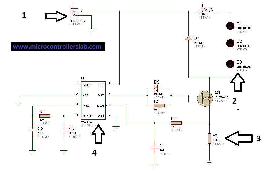
The above circuit can be used to power 1.5A series LEDs. In the above circuit, the following are the main components of the LED driver:
- UC3842 current mode controller IC.
- MOSFET IRLZ34NS as a switch
- Current limiting resistor R1.
- inductor design
Certainly! Here’s a clearer explanation of the content for each label in the block:
Label 1 (Buck Converter): The input side of the driver refers to the power source that is connected to the driver. In this case, the input voltage range is between 10 and 25 volts. However, we want the driver to provide a regulated output voltage of 9 volts. To achieve this, a buck converter is used. A buck converter is a type of DC-to-DC converter that steps down the input DC voltage to the desired output voltage. It consists of components such as an inductor, a diode, and a MOSFET.
Label 2 (LEDs in Series): Label two in the diagram represents a string of three LEDs connected in a series configuration. Connecting LEDs in series means that the positive terminal of one LED is connected to the negative terminal of the next LED, forming a chain.
Label 3 (Current Limiting Resistor): Label three depicts the current limiting resistor in the LED driver circuit. This resistor is used to control the amount of current flowing through the LEDs. To select the appropriate value for the current limiting resistor, we need to know the desired current. In the given circuit, the LED driver can power LEDs up to 1.5 Amperes. The current limiting resistor acts as a current sensing shunt resistor and is connected to the current sensing pin of the UC3842, a current mode PWM controller. By using Ohm’s law and knowing that the reference voltage at the current sensing pin is 1 volt, we can determine the value of the current limiting resistor to ensure the desired current flow.
V = IR
R = V / I = 1 / 1.5 = 0.67 ohm
Note: The resistor power rating should be more than 0.5 watts.
Label 4: The UC3842 is used as a current mode PWM controller. Whenever the current increases or decreases from 1.5 Amperes, it adjusts the on or off time of MOSFET Q1 by adjusting the duty cycle of PWM.
Note: The inductor used in the above circuit diagram should be made using a ferrite core, and the proper wire should be selected to make the inductor according to the current rating of the LED driver.
Conclusion
In conclusion, this article provided a comprehensive overview of LED drivers, their applications, and the different configurations in which LEDs can be arranged. Additionally, a practical example of a series LED configuration using the UC3842 current mode controller was presented, along with a detailed circuit diagram and component explanation. LED drivers play a crucial role in regulating the output voltage for a string of LEDs, ensuring the proper functioning and longevity of the lighting system. By understanding the different LED configurations and the considerations involved in designing an LED driver, engineers, and hobbyists can make informed decisions when implementing LED lighting solutions. With the advancements in LED technology and the increasing popularity of energy-efficient lighting, LED drivers continue to play a vital role in the field of illumination.
Related content:
Great Article for Biggners,,,,You are doing Great Work,,Bhaijan
Great Article for beginners,,,,You are doing Great Work,,Bhaijan
thanks 🙂 share website with your friends 🙂
good notes.
do you have any details or help for switching capacitors using thyristors for powerfactor correction?
good
UC3842 has an input voltage limited to 30V, I have a supply from the PV(photovoltaic). what do you advice I do to power the UC3842 IC.
You could use an off the shelf buck converter module with a high input voltage range.
Hey! Brilliant idea and explanation, Can you please explain how this circuit can be commercialized, and if it can’t be what is the problem, I have gone across several PCBs for LED bulbs, all of them were using BP3133A for the same purpose, can we replace BP3133A with UC3842?
With this circuit, the supply voltage will be limited by Vgs Max of the Mosfet. In case of IRLZ34N this will be 16V. A supply of 25V will possibly kill the Mosfet and all LED’s!
Hi, What an impressive post! The way you sum-up this topic briefly, shows your professionalism. Transformed my outdoor space with low voltage landscape lighting. The subtle glow creates a magical ambiance. Efficient and aesthetically pleasing.