In this article, you will learn how to design a solar inverter for home lighting and low-power applications, without the need for a microcontroller. We will be using the popular SG3525 pulse width modulation (PWM) controller IC for this project. This article will cover the following topics:
- Introduction to solar inverters
- Circuit diagram of the solar inverter
- Understanding the SG3525 PWM IC and its role in the project
By the end of this article, you will have a solid understanding of how to build a solar inverter using the SG3525 PWM controller IC. Let’s get started!
What is a Solar Inverter?
As its name suggests, a solar inverter is used to convert solar DC power into AC power. Solar panel energy is stored in batteries using a solar charge controller. DC power stored in batteries is then converted into AC power using an inverter. An inverter is a power electronics DC to AC converter. There are many applications of inverters in power systems, industrial settings, and domestic usage. The block diagram of a solar inverter is shown below. The block diagram of the solar inverter given below is self-explanatory. If you still have any questions about it, please feel free to ask in the comments.
The block diagram provided illustrates the components and their connections in a solar inverter system. Here’s a breakdown of each element in the diagram:
- Solar Panels: These are the primary sources of power in a solar inverter system. Solar panels capture sunlight and convert it into DC (direct current) electricity.
- Solar Charge Controller: The solar charge controller is responsible for regulating the amount of charge flowing from the solar panels to the battery bank. It ensures that the batteries are charged efficiently and prevents overcharging or discharging.
- Battery Bank: The battery bank stores the DC power generated by the solar panels. It acts as an energy reservoir and provides a continuous power supply even when sunlight is not available.
- Inverter: The inverter converts the DC power stored in the battery bank into AC (alternating current) power, which is the standard type of power used in most electrical appliances and devices.
- Output Waveform Filter: This component filters the output waveform from the inverter to ensure it is a smooth and stable AC signal. It helps in reducing harmonic distortion and providing clean power to connected loads.
- Loads: Loads refer to the electrical appliances or devices that receive power from the solar inverter system. These can range from household lighting and appliances to industrial equipment.

A solar charge controller is used to charge the battery bank. It is essential to use a solar charge controller to charge the battery bank, as failure to do so may result in damage to your batteries due to overcharging and discharging. There are various types of inverters available in the market. Based on the output waveform, there are three types of inverters available in the market:
- Square wave inverter
- Modified sine wave inverter
- sine wave inverter
You can find more information about different types of inverters here:
- Difference Between Ferrite Core and Iron Core Inverters
- What is Inverter? What is Difference Between Different kinds of Inverters Available in market?
You can use any kind of inverter, but it is recommended to use a pure sine wave inverter because it has a lot of advantages compared to other types of inverters.
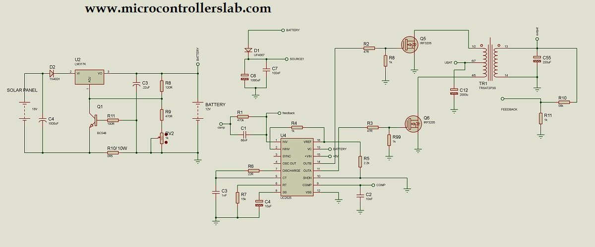
Solar Inverter Circuit Diagram
The circuit diagram of a solar inverter using SG3525 is given below. I have explained all the main components and their working below. I also posted a separate article on the pulse width modulation IC or PWM controller IC SG3525. Let’s start with the basic working of this project.
SG3525 is used to control the output voltage of the inverter by the feedback voltage control method. It is also used to drive MOSFETs connected to the transformer. Both MOSFETs are used in the low-side connection. SG3525 has a built-in totem pole circuit to drive the low-side connected MOSFETs. I have posted a separate article on the working of SG3525 and its configuration. I have explained everything you need to know to use SG3525 PWM controller IC. To know more about it, check this article:
Working
The circuit diagram shown above illustrates a solar inverter using the SG3525 PWM controller IC. Here’s an explanation of how the circuit works:
In this circuit diagram, the push-pull topology of DC to DC converters is used to convert a DC voltage source into an AC voltage. A step-up transformer is used to increase the voltage from 12 volts to 220 volts AC. A center-tap transformer is used in this project. A voltage divider circuit is used at the output to provide feedback to the SG3525. The SG3525 controls the duty cycle of PWM using this feedback voltage.
The overall working of this circuit involves the solar panels generating DC power, the solar charge controller regulating the charging of the battery bank, and the SG3525 PWM controller IC controlling the output voltage of the inverter. The inverter then converts DC power from the battery bank to AC power, and the voltage divider circuit provides feedback to the SG3525 to regulate the duty cycle of the PWM signal.
Components
- Solar Panels: The solar panels convert sunlight into DC (direct current) electricity. The generated DC power is then fed into the circuit for further processing.
- Solar Charge Controller: The solar charge controller regulates the amount of charge flowing from the solar panels to the battery bank. It ensures that the batteries are charged efficiently and protects them from overcharging or discharging.
- Battery Bank: The battery bank stores the DC power generated by the solar panels. It acts as an energy reservoir, providing a continuous power supply even when sunlight is not available.
- SG3525 PWM Controller IC: The SG3525 is a pulse width modulation (PWM) controller IC that plays a crucial role in controlling the output voltage of the inverter. It drives the MOSFETs connected to the transformer and provides feedback voltage control. The SG3525 has a built-in totem pole circuit to drive the low-side connected MOSFETs.
- Inverter: The inverter converts the DC power stored in the battery bank into AC (alternating current) power, which is the standard type of power used by most electrical appliances and devices. The SG3525 PWM controller IC controls the voltage output of the inverter.
- Step-Up Transformer: A step-up transformer is used to increase the voltage from 12 volts (DC) to 220 volts (AC). This transformer allows the inverter to provide the desired level of AC voltage.
- Center Tap Transformer: The center tap transformer is a specific type of transformer used in this project. It helps in generating the required AC voltage and allows for better control and stability.
- Voltage Divider Circuit: The voltage divider circuit is used to provide feedback to the SG3525 PWM controller IC. It helps regulate the duty cycle of the PWM (pulse width modulation) signal, thereby controlling the output voltage of the inverter. The feedback voltage from the voltage divider circuit controls the duty cycle of the PWM signal.
If you want to design a solar charge controller of a high rating, please check the following article:
Related content:
hi……………tell me connection of source1 and ubat please…………………where i connect it
ubat with battery and source1 with pin 13 of sg3525 and it is mintakenly written battery on pin 13
hello,
your inverter is a square wave inverter? what is the efficiency for this design?
It is square wave inverter and efficiency is 60%. But efficiency can be increased by using chopper technique and microcontroller
hello sir ,
I want to a required embedded C coding of this project, plz send me on my email iD,
patel.priyank00000@gmail.com
there is no need of c code if you use sg3525 IC but if you want to use microcontroller you have to write code. if you want to hire me for this project code writing contact me at microcontrollerslabhub@gmail.com
Cellphone num
Shalom bilal malik in your circuit what transformer you use? Is it iron core? or ferrite?
Shalom bilal malik posible to have your working simulation on this circuit
Hi…mr. bilal at the output of the transformer you put ditectly electrolytic capacitor without rectifying a diode for feedback ohh i dont think that will woks
can u send me proteous diagram and code of micro controller
please could you explain the solar charge controller section? I try to understand it, but its a little fuzzy, the lm317 and the small transistor…how does the circuit there regulate the charge rate?
hello sir I really appreciate ur good work. can you help me with a circuit of low voltage cutoff and fully charge cutoff of an inverter
i am electrical final year student.i want to make a solar invertor for final year project.please give me a suggestion for my project and also give a suggestion with micro controller project is best or without micro controller project is best for solar invertor?
‘Design and implementation of smart solar power system’, can anyone help me on this project?
Which aspect of the power system do you want
I was wondering if you knew the Ohm value for the 10W R10 resistor. Also, I am using a 5 volt battery pack to power pin 15 of the IC unit
Hello sir,
I am Electrical Final year student, I need this project base paper and IEEE format with journels .