Pakistan has been facing load shedding due to electricity demand being more than the production power of the national grid. The country is unable to execute plans to enhance power production because of a shortage of budget. However, Pakistan is blessed with many renewable and non-renewable energy resources. All we need to do is wisely and effectively utilize these resources.
In our country, we are rich in renewable energy sources. In the summer, the sun shines for about eight to ten hours per day in most parts of the country. Similarly, in the winter, the duration of a sunny day is shorter but still present. On the other hand, we are also blessed with wind energy, although it is comparatively lesser than solar energy. We can utilize this energy to make users independent in power production.
Pure Sine Wave Inverter Introduction
This project deals with understanding and implementing a hybrid pure sine wave inverter. The hybrid inverter utilizes two sources, such as solar and wind. The implementation process consists of several parts. We begin by simulating a DC to DC converter using push-pull topology in Proteus and then implementing it on hardware. Next, we simulate an inverter using H-bridge topology and implement it on hardware. We use SPWM to generate a pure sine wave. To obtain a pure sine wave, we design an LC filter. Finally, since the output of sources is not constant, we design a voltage regulator using Buck topology in MATLAB. We control its response using PID in Proteus and then implement it on hardware.

Project Overview
A hybrid system combines solar and wind technologies together. Both solar panels and wind generators generate DC power, so an inverter is necessary to convert the direct current into alternating current. The DC-AC inverters typically operate using a technique called Pulse Width Modulation (PWM). PWM is a highly advanced and useful technique that controls the width of the gate pulses through various mechanisms. A PWM inverter maintains the output voltage of the inverter at the rated voltage, regardless of the output load chosen by the user.
In a conventional inverter, the output voltage changes according to the load changes. To nullify this effect of changing loads, the PWM inverter corrects the output voltage by changing the width of the pulses. The output AC depends on the switching frequency and pulse width, which are adjusted according to the value of the load connected to the outputs, providing a constant rated output. The inverters usually operate in a pulse width modulated (PWM) way and switch between different circuit topologies. This means that the inverter is a nonlinear, specifically piecewise smooth system. In addition to this, the control strategies used in the inverters are also similar to those in DC-DC converters. Both current-mode control and voltage-mode control are employed in practical applications.
Pure Sine Wave Inverter Selection Criteria
In order to maximize output it is important to select an inverter with the following characteristics.
- High efficiency
- Low standby losses
- High Surge capacity
- Low harmonic distortion
All grid connected inverters are pure sine wave inverters. Pure sine wave inverters are used to operate sensitive electronic devices that require high quality waveform with little harmonic distortion. In addition they have high surge capacity which means they are able to exceed their rated wattage for a limited time. This enables power motor to start easily which can draw up to seven times their rated current during startup. Virtually any electronic device will operate with output of pure sine wave inverter.
Application of PSW Inverter
Some electronic devices may pick up inverter noise while operating with modified wave form. Fluorescent tube light works smoothly with pure sine wave inverter. Some appliances such as microwaves, drill machines, clocks or speed motors will not produce full output, if they don’t use sine wave current , moreover they may damage the equipment,. Some loads such as dimmers will not work at all.
It is safe to say any electronic device that requires sensitive calibration can only be used with pure sine wave inverters.
Pure Sine Wave Inverter Circuit Diagram and Working
In our last article on SPWM generation, we discussed how to implement sinusoidal pulse width modulation using a microcontroller and how to select the number of pulses and duty cycle for each pulse. We used the PIC16F877A microcontroller to write the code for SPWM. You can use any microcontroller of your choice, but the procedure will remain the same as we discussed in the last article on SPWM generation.
We have used 100 pulses, and the frequency of each pulse is 20 kHz. Hence, the timer period of each pulse is equal to 2 * 50 µs = 100 µs. Therefore, we have used 100 pulses as we mentioned in the previous article. The greater the number of pulses, the more pure sine wave will be produced. We have calculated the duty cycle for 100 pulses using the same method we discussed earlier. Array of the duty cycle is:
duty cycle for hundred pulses = {0, 8, 16, 24, 31, 39, 47, 55, 62, 70, 77, 85, 92, 99, 106, 113, 120, 127, 134, 141, 147, 153, 159, 165, 171, 177, 182, 188, 193, 198, 202, 207, 211, 215, 219, 223, 226, 229, 232, 235, 238, 240, 242, 244, 246, 247, 248, 249, 250, 250};Code
The code for this project is written in the MIKROC compiler and 8Mhz crystal is used in this project. If you do not know how to use MikroC for Pic, you can refer to these tutorials:
- How to Use “MikroC PRO for PIC” to Program PIC Microcontrollers
- Pic microcontroller programming in c using Mikroc Pro for PIC
const unsigned char SinLkUpTab[50]= {0, 8, 16, 24, 31, 39, 47, 55, 62, 70, 77, 85, 92, 99,
106, 113, 120, 127, 134, 141, 147, 153, 159, 165, 171, 177, 182, 188, 193, 198, 202, 207,
211, 215, 219, 223, 226, 229, 232, 235, 238, 240, 242, 244, 246, 247, 248, 249, 250, 250};
unsigned short cnt,inc,dec,sqinc,cnt1;
void interrupt()
{

if (dec==0)
{cnt++;
PWM1_Set_Duty(SinLkUpTab[cnt]);
}
else if (dec==1)
{cnt–;
PWM1_Set_Duty(SinLkUpTab[cnt]);
}

TMR1IF_bit = 0; // clear TMR0IF
TMR1H = 0xFF; // Initialize Timer1 register
TMR1L = 0x76;
}
void main()
{
TRISB = 0; // designate PORTB pins as output
PORTC = 0; // set PORTC to 0
PORTB = 0; // set PORTC to 0
TRISC = 0; // designate PORTC pins as output
TRISA = 0; // designate PORTB pins as output
PORTA = 0; // set PORTC to 0
T1CON= 0b00000001; // Timer1 settings
TMR1IF_bit = 0; // clear TMR1IF
TMR1H = 0xFF; // Initialize Timer1 register
TMR1L = 0x76;
TMR1IE_bit = 1; // enable Timer1 interrupT
cnt = 0; // initialize cnt
*** Note: This is not a complete code
You can contact us at microcontrollerslabhub@gmail.com to purchase code and simulation.
Pure Sine Wave Inverter Circuit Simulation Results
Demonstration
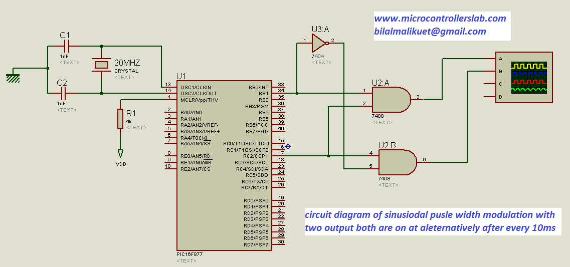
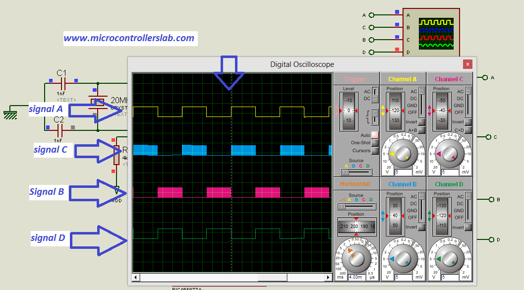
The diagram below shows the circuit diagram of sinusoidal pulse width modulation with two outputs that are on alternatively after every 10 ms.
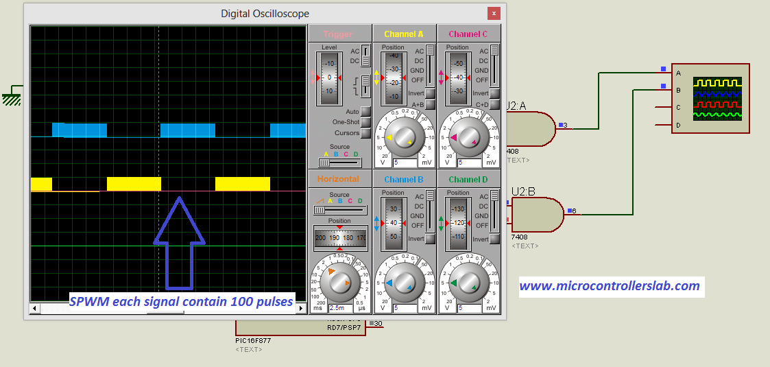
The output of the SPWM circuit diagram
Gating signals for H bridge
Now we will discuss how to use the above circuit for generating four gating signals for an H-bridge, which we have already discussed in the above articles. We have taken two more outputs from the same circuit to generate four gating signals for the H-bridge. The circuit diagram is shown below:
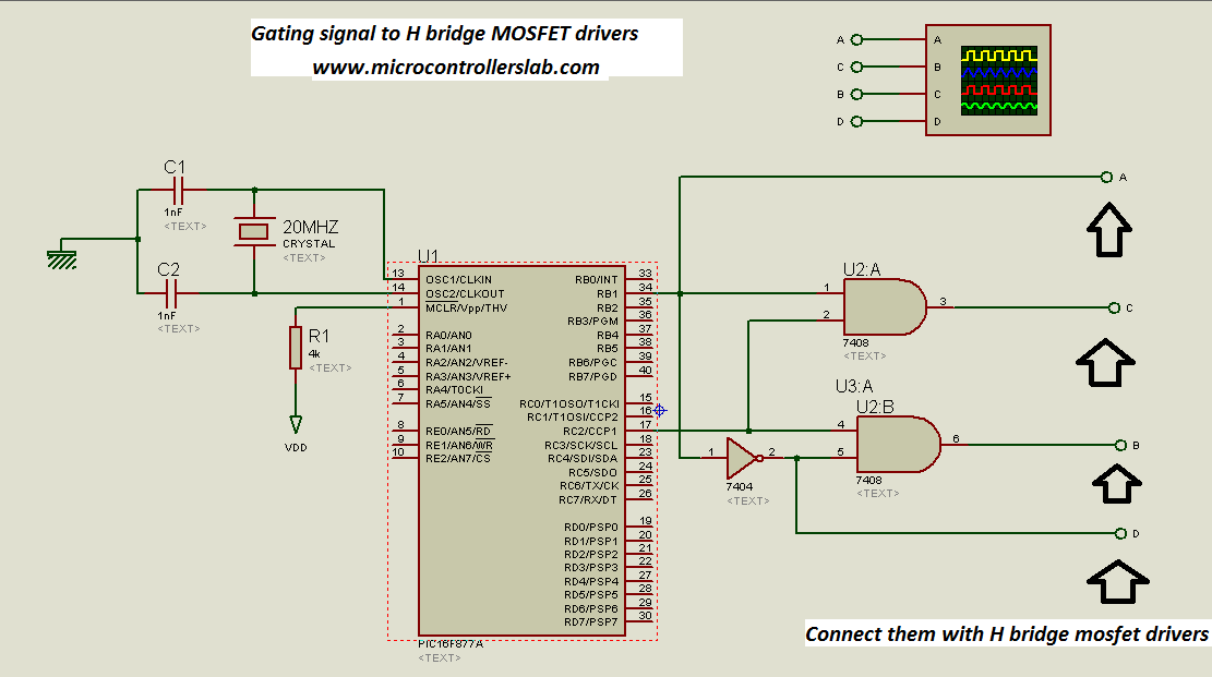
The output of SPWM circuit gating signals for H bridge:
Use the above circuit to drive the MOSFETs of the H-bridge through MOSFET drivers IR2110. I have explained everything about pure sine wave inverters using switch mode techniques. Starting with a basic overview of pure sine inverters and their types. After that, I have discussed the use of the voltage mode PWM controller SG3525 and its applications. Then, I explained the MOSFET driver IR2210 and its usage. I also discussed a DC-to-DC converter using the push-pull topology and how to create an H-bridge using IR2110. I have written a detailed article on sinusoidal pulse width modulation. Now, you can utilize all the knowledge you have gained to create a pure sine wave inverter. Simply connect a low-pass filter at the output of the H-bridge, and you will obtain a clean and precise pure sine wave output.
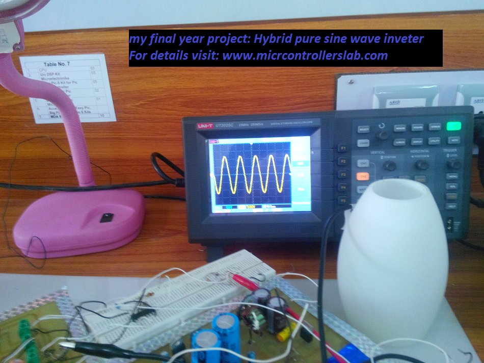
I have obtained a pure sine wave in my final year project, “Hybrid Pure Sine Wave Inverter,” by connecting an LC filter at the output of the H Bridge. The LC values I used are L = 2mH and C = 3.3uF. The diagram illustrating the pure sine waveform I achieved in my final year project is shown in the figure below:
NOTE: It is difficult to simulate this circuit in Proteus. You can easily obtain a pulsating wave output result in Proteus. However, when you connect an LC filter at the output of the H Bridge, Proteus will not simulate your circuit. We suggest you make this circuit on hardware and verify the results.
Conclusion
In conclusion, this article provided a comprehensive overview of how to create a pure sine wave inverter circuit diagram. It covered topics such as the use of a push-pull converter, sinusoidal pulse width modulation, an H-bridge, and a low-pass LC filter. Key concepts and considerations were explained, including the selection of pulses and duty cycle for each pulse. The article also highlighted the importance of using a pure sine wave inverter for powering sensitive electronics and appliances, along with its applications in off-grid or backup power systems, RVs, boats, and solar power systems. Furthermore, the article delved into the intricacies of generating gating signals for the H-bridge and emphasized the use of MOSFET drivers for this purpose. Overall, with the knowledge gained from this article, readers can confidently design and construct their own pure sine wave inverter systems, ensuring a reliable and clean power supply for their specific needs.
You may also like to read:
- Three-phase sine wave inverter using PIC microcontroller
- dsPIC33F microcontroller-based pure sine wave inverter
- Single-phase pure sine wave inverter using Arduino
- Three-phase sine wave inverter using Arduino
- Modified sine wave inverter using PIC microcontroller
Keep visiting my blog for more practical knowledge and final year project ideas. Remember me in your prayers in return.
Great Work. It’s worth appreciating your generosity. Please upload rest of the tutorials on Pure Sine Wave Inverter soon.
Eagerly waiting
Emaniac
thanks. I will upload 2-3 articles on pure sine wave inverter soon. Keep visiting my blog and you should subscribe to my blog to get info about next articles.
sir send me full project
hello mr bilal
I am doing the same project as a third year project using mbed microcontroller.
I have a dc to dc converter from 24 to 70 volt (push-pull topology), as asupply . H-bridge using 4 mosfets which are controlled by the mbed. I have a problem that the output ( without filter) is fluctuating momentarily and also the power factor is not unity while the load is resistor!! could you help me please
nice work please up load full text
I’m doing the same project micro controller based power invert er for industrial application
you can contact me at microcontrollerslabhub@gmail.com if you want to purchase full code and project report
What will be cost of making this project Pure sine wave inverter using PIC microcontroller
What’s up, its pleasant paragraph concerning media print, we all be aware of media is a enormous source of facts.
THANKS GREAT ENGINEER. PLEASE, I NEED YOUR HELP WITH A WORKING CIRCUIT DIAGRAM AND CODE FOR THE PURE SINE WAVE INVERTER. LOVE YOU
my project also same .i need your help
Thank You! So much for a great blog and best of luck for the future,
I’ll be in touch and love to get improvement.