A modified sine wave inverter is designed by utilizing a PIC microcontroller and a push-pull topology. The push-pull configuration operates MOSFETs as switches and a control circuit controls them to produce a stepped-up battery voltage with a modified sine wave form. The control signal is generated by the PIC16F87A microcontroller. At the end of this article, we discuss the control circuit. To drive both low-side MOSFETs, the MOSFET driver IR2210 is employed. If you are unfamiliar with the MOSFET driver IR2110, I recommend reading the following article to learn how to utilize it as a low-side MOSFET driver.
What is a Modified Sine Wave Inverter?
A Modified Sine Wave Inverter, also known as a quasi-sine wave inverter or stepped sine wave inverter, is a type of power inverter used to convert direct current (DC) electricity, typically from a battery or solar panel, into alternating current (AC) electricity with an output waveform that approximates a sine wave. However, the output waveform is not a pure sine wave but rather a modified or stepped approximation of a sine wave. This type of inverter is a more cost-effective and simpler solution compared to pure sine wave inverters.
Modified sine wave inverters generate an output waveform that resembles a stepped waveform with multiple levels, rather than the smooth and continuous curve of a pure sine wave. While modified sine wave inverters are suitable for many basic appliances and devices, some sensitive equipment such as certain types of motors, audio equipment, and medical devices may not operate optimally with this type of waveform. In these cases, pure sine wave inverters are preferred because they produce a cleaner and more precise AC waveform, similar to what you get from the grid. However, for many common household applications and devices, modified sine wave inverters are a cost-effective and practical choice for converting DC power into usable AC power.
Block Diagram
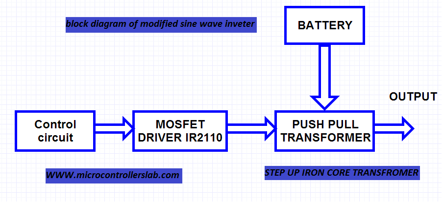
The block diagram illustrates the components and connections involved in the design of a modified sine wave inverter using a PIC microcontroller and a push-pull topology. Here is a breakdown of the different sections of the block diagram:
- The PIC16F87A microcontroller generates the control signal for the inverter. It determines the timing and waveform shape for the output.
- The control circuit receives signals from the PIC microcontroller and generates control signals for the MOSFET driver. It ensures that the MOSFETs turn on and off in a specific manner to produce the desired modified sine wave output.
- The IR2210 MOSFET driver is used to control the low-side MOSFETs in the push-pull configuration. It provides the necessary gate voltage to fully drive the MOSFETs.
- The push-pull configuration consists of two MOSFETs (IRF3205) connected to a center-tapped iron core transformer. The MOSFETs operate alternately, ensuring that only one MOSFET is on at any given time.
- The iron core transformer steps up the battery voltage to produce an output voltage suitable for powering AC loads. It is the key component responsible for generating the modified sine waveform.
The block diagram provides an overview of the major components and their interconnections in the modified sine wave inverter design. It showcases the sequential operation of the control circuit and the MOSFETs, leading to the production of a modified sine wave at the output of the transformer.
Control Signals with Pic Microcontroller
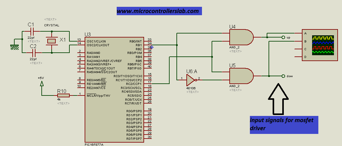
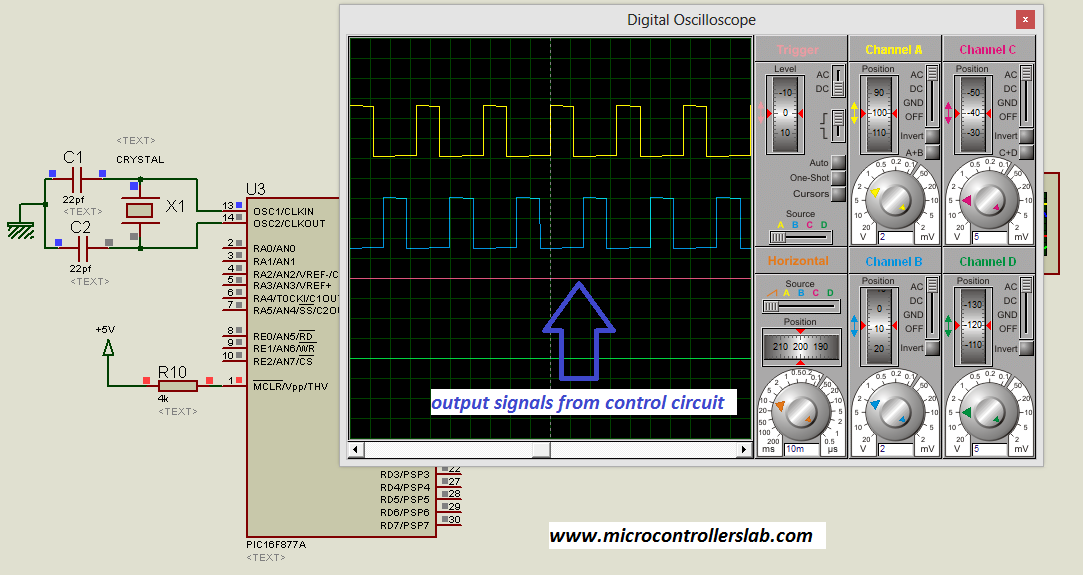
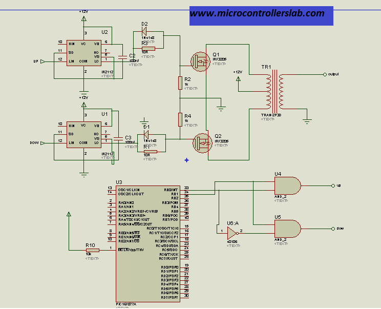
The control circuit generates signals for the MOSFET driver, which turns the MOSFET of the push-pull high-voltage transformer on and off. This action produces a modified sine wave at the output of the high-voltage step-up transformer. The control signal is generated by the PIC16F877A microcontroller. To ensure that only one MOSFET is on at a time, an AND gate or NOT gate generates two signals for the low-side MOSFETs. It is important to prevent both MOSFETs from turning on simultaneously to avoid a short circuit, which can cause damage to the inverter if a protection circuit is not used. Please refer to the circuit diagram and the output of the control signals below:
Push-pull Circuit and Transformer Selection
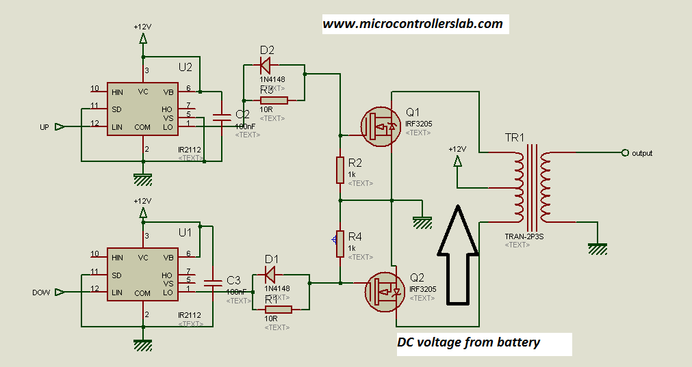
This project utilizes a push-pull topology and an iron-core transformer to generate a modified sine wave. The circuit diagram of the push-pull transformer demonstrates this. We employ the IR2210 MOSFET driver as the low-side MOSFET driver to fully operate the MOSFETs. Providing a gate signal of 10 volts is necessary for optimal MOSFET performance, whereas the voltage level of the control signals from the control circuit only reaches around 5 volts. Thus, the MOSFET driver is used to drive the low-side MOSFETs. It is important to note that a single MOSFET is used in this illustration. In actual implementation, you should connect the MOSFETs in parallel based on the power rating of your inverter. Additionally, be sure to incorporate appropriate heat sinks for the MOSFETs.
NOTE: Use separate heat sinks for MOSFETs connected to the upper and lower legs of the push-pull transformer. Otherwise, the drains of both sides will become shorted, resulting in a short circuit. I made this mistake when I started working on power electronics projects and ended up getting a serious shock. 😀
you may also like ” Pure sine wave inverter tutorials “
In the circuit diagram below, we utilize a parallel combination of a diode and resistor to rapidly discharge the gate capacitance and initiate the deactivation of the MOSFET. This step is carried out before activating the MOSFET connected to the other branch of the push-pull transformer. To generate modified sine wave AC voltage, a 12-volt battery serves as the primary DC power source. Alternatively, when employing a 24-volt battery bank, it becomes necessary to opt for a specific push-pull transformer designed to elevate the voltage from 24/1.414 volts to the required 220 volts AC level.
Complete Circuit Diagram
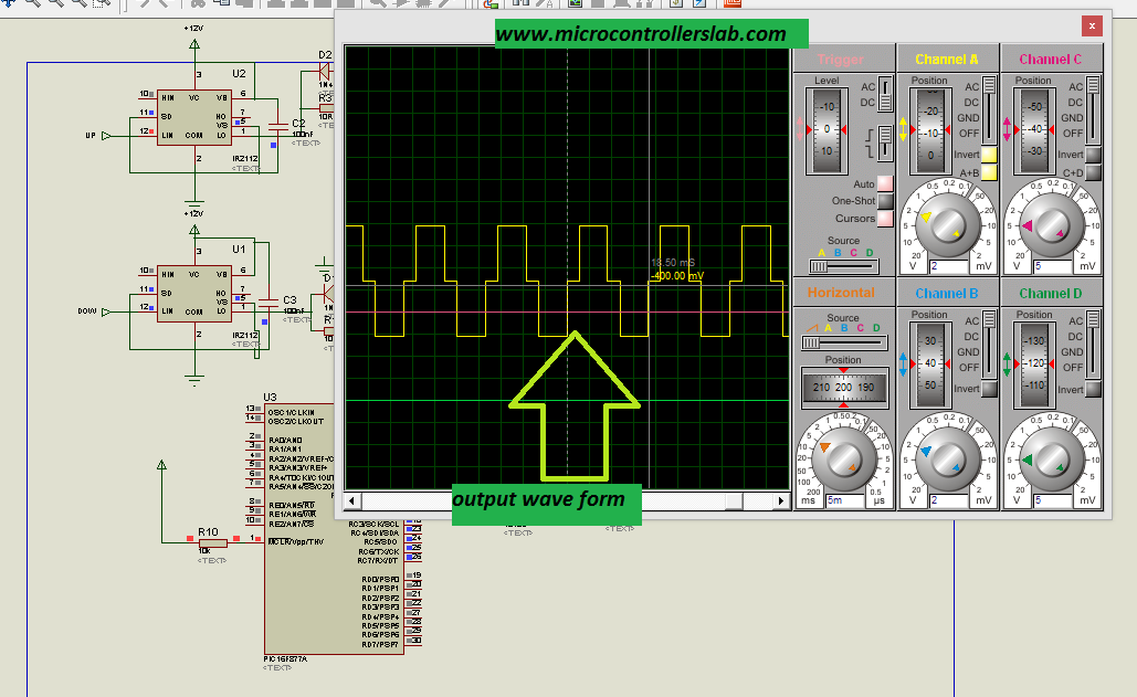
The figure below shows the complete circuit diagram and output waveform of the modified sine wave.
Output waveform from a modified sine wave inverter:
Components list :
Resistors,"R1",10R,
Resistors,"R3",10R,
Resistors,"R2",1k,
Resistors,"R4",1k,
Resistors,"R5",300,
Resistors,"R10",10k,
Capacitors,"C1",1000uF,
Capacitors,"C2",100nF,
Capacitors,"C3",100nF,
Integrated Circuits,"U1",IR2112,
Integrated Circuits,"U2",IR2112,
Integrated Circuits,"U3",PIC16F877A,
Integrated Circuits,"U4",AND gate,
Integrated Circuits,"U5",AND gate,
Integrated Circuits,"U6",40106,
Transistors,"Q1",IRF3205,
Transistors,"Q2",IRF3205,
Diodes,"D1",1N4148,
Diodes,"D2",1N4148,
crystal 12Mhz
Iron core transformer 12-220 volt
Code
The code for this project is written in the MIKROC compiler and 8Mhz crystal is used in this project. If you do not know how to use MikroC for Pic, you can refer to these tutorials:
- How to Use “MikroC PRO for PIC” to Program PIC Microcontrollers
- Pic microcontroller programming in c using Mikroc Pro for PIC
// Microcontrollers Lab Hub
// Email: microcontrollerslabhub@gmail.com

// Declare a global variable 'cnt' to keep track of interrupt counts
unsigned cnt;

// Interrupt Service Routine (ISR)
void interrupt() {
    cnt++; // Increment the counter

    if (cnt == 3)
        PORTC.f2 = 1;  // Toggle PORTC.f2 to turn ON an LED
    else if (cnt == 17)
        PORTC.f2 = 0;  // Toggle PORTC.f2 to turn OFF an LED
    else if (cnt == 20) {
        cnt = 0;
        PORTB.f1 = ~PORTB.f1;  // Toggle PORTB.f1 to turn ON/OFF an LED
    }

    TMR1IF_bit = 0;  // Clear Timer1 overflow interrupt flag
    TMR1H = 0xf6;  // Initialize Timer1 high register
    TMR1L = 0x65;  // Initialize Timer1 low register
}

void main() {
    TRISB = 0;  // Set PORTB as an output
    TRISC = 0;  // Set PORTC as an output
    PORTC = 0;  // Initialize PORTC to all zeros

    PORTB = 0x00;  // Initialize PORTB to all zeros
    T1CON = 0b00000001;  // Timer1 settings
    TMR1IF_bit = 0;  // Clear Timer1 overflow interrupt flag
    TMR1H = 0xf6;  // Initialize Timer1 high register
    TMR1L = 0x65;  // Initialize Timer1 low register
    TMR1IE_bit = 1;  // Enable Timer1 interrupt
    INTCON = 0xc0;  // Enable Timer0 interrupt

    cnt = 0;  // Initialize the counter to zero

    do {
        PORTC.F0 = 1;  // Set PORTC.F0 to 1
        delay_ms(1000);  // Delay for 1 second
        PORTC.F0 = 0;  // Set PORTC.F0 to 0
        delay_ms(1000);  // Delay for 1 second
    } while (1);  // Infinite loop
}
How Does Code Work?
The provided code controls an IR2112 Mosfet driver for a modified sine wave inverter. In the first section, the code initializes various hardware settings and configurations. It sets up the microcontroller’s ports and pins, specifying which ones use for output and initializes them to appropriate values. The code also configures Timer1 to generate periodic interrupts, which are crucial for timing and control in the inverter’s operation. The interrupt service routine (ISR) implemented in the code manages the interrupt events, allowing for precise control of the inverter’s output. Additionally, the code includes a loop that alternates the state of a specific output port to simulate the generation of a modified sine wave, which is a key functionality of an inverter.
In the main section, the code continues the execution of the main program loop, which primarily involves generating the modified sine wave output. The loop toggles the state of a specific output pin with a defined delay to create the waveform. The IR2112 Mosfet driver is likely responsible for driving the power transistors used in the inverter to switch them on and off as required to generate the modified sine wave output.
Conclusion
In conclusion, the article provides a comprehensive overview of the design and operation of a modified sine wave inverter using a PIC microcontroller and a push-pull topology. The block diagram helps to visualize the interconnections between various components, such as the PIC microcontroller, control circuit, MOSFET driver, push-pull configuration, and iron core transformer. The control signals generated by the PIC microcontroller are crucial in determining the timing and waveform shape of the output.
You may also like to read:
- Three-phase sine wave inverter using PIC microcontroller
- dsPIC33F microcontroller-based pure sine wave inverter
- Single-phase pure sine wave inverter using Arduino
- Three-phase sine wave inverter using Arduino
- Pure sine wave inverter circuit diagram
- Three-phase variable frequency SPWM for VFD using PIC microcontroller
there is no feedback in the sample code …. can you kindly show an example using feedback with TMR1
yes because feedback implementation is done through dc to dc converter using sg3525
@ Malik in your component list, you mentioned iron core transformer, which means you not using the high frequency approach so why not implement feedback in code???
Assalam o alaikum bilal bhai when i make a component in proteus and then stimulate it it shows error regarding new component that the new component is not running which fails stimulation. Can you please tell me how to correct this error? In your design you have make many integrated circuit design chips using proteus and you are also getting output from them. Please tell me how to make my own made components function correct in run time stimulation in proteus.
Protrus usually do not simualte power electronics circuits. Try to build practical circuit
dear sir which programmer is best for pic microcontroller
what is difference b/w jdm programmer and pickit 2
Hi Malik,
The micro controller based modify sine wave inverter is very good project which i will like to implement. Please kindly guide me on how i can add feedback control to the project.
and 60hz like putting
Dear Sir,
I am not getting pwm signal, its just a square waveform. What could be the error. Please help me.
a.o.a i have generated a square wave with 5ms on and 15ms off and alternate on other pin and fed it to the mosfets but didnot get the modified sinewave at the output plz advise
What is the frequency of generated PWM Wave generates by microcontroller?
I have used gate driver IC IR2110 . Also I have used the gate driver circuit you have given. But I have not gotten the output. Please give me some suggestion regarding the gate driver.
tell mw the frequency of PWM plz that we genereate through PIC 18F877A
You are great man.
Great job man, but work not completed cos no feedback in ur code.can I get the complete code.