Control-Integrated circuit for SMPS SG3525: Pulse frequency modulation and pulse width modulation are two types of techniques used in control integrated circuits for switch-mode power supplies. In Pulse frequency modulation technique on time of pulse remains constant but the frequency increases with the increase in load. But the Pulse frequency modulation technique causes some issues in switch-mode power supplies. On the other hand in Pulse width modulation technique frequency remains constant but the width of pulse changes with the change in load. The width of the pulse or on time increase with the increase in load. Pulse width modulation also resolves the issues which occur in Pulse frequency modulation. Therefore, Pulse width modulation is a preferred technique for control circuits of switch-mode power supplies.
Types of PWM controllers
There are many PWM ( Pulse width modulation ) controller integrated circuits available in the market just like SG3525. These PWM controllers ICs you can use very easily in your SMPS projects by connecting some external circuitry with them according to the selection of frequency. I will discuss these things in detail later in this article. There are two types of PWM controller integrated circuits:
- Voltage control PWM controller
- current control PWM controller
The voltage control method used a feedback voltage by comparing it with a reference value to set a duty cycle of PWM. In return to control the output voltage of SMPS. While the current control method uses Output current from output inductor to compare it with the reference value and to set the duty cycle of PWM. I have used a voltage mode PWM controller in pure sine wave inverter. Sg3525 is used in Dc to DC converter part to control the output voltage and for switching of MOSFETS connected to push-pull converter chopper.
Introduction to SG3525
- It is a pulse width modulation controller IC which has 16 pins.
- It provides two pulse width modulator signal which is a complement of each other.
- It is used to generate a PWM signal for power electronics projects and also for switch-mode power supplies.
- It offers feedback circuitry to control the output voltage by comparing the feedback signal with a reference voltage.
- It has a protection circuitry that shutdown the PWM signal based on the feedback current limit.
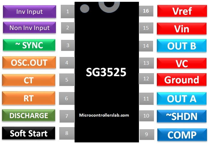
SG3525 pinout diagram
This is a pin configuration diagram and the functionality of each pin is provided in the next section.
Features of SG3525
- It can operate with a supply voltage of between 8 and 35 volts. It may damage above 40 volts.
- It also has an external oscillator synchronization pin.
- It has a pulse to pulse shutdown capability.
- It can operate with a frequency range of 100 to 400KHz.
- It also provides a feature of versatile dead-time control between switching signals to turn on or off devices like MOSFETs, IGBTS and power transistors.
- The maximum power dissipation is about 1000mW.
- Other similar integrated circuits are SG2525, UC3525.
- For further features and specifications check datasheet.
How and Where to use SG3525
- Sg3525 is a voltage mode PWM controller integrated circuit. It is used in maximum inverters available in the market.
- Even top inverters manufacture companies also use Sg3525 in dc to dc converter part of the inverter. It is a 16 pin integrated circuit.
- It has two PWM outputs both are an inversion of each. Another advantage of SG3525 is that it has a built-in totem pole base PWM driver.
- If you want to know about the internal architecture of SG3535. Search its datasheet.
- Output pins can driver semiconductor devices up to a current range of 50mA. For example, if you are using a switch that requires more than 50mA to operate, then you will have to use driver IC as MOSFET driver IR2110.
- The description and functionality of each pin are given in the next section on the pinout of sg3525.
Working with the functionality of each pin
The above diagram shows the pin configuration of SG3525. Description of each pin is given below:

- Pin 1 is an inverting pin and pins 2 is a noninverting pin. If the voltage on the inverting pin is greater than the voltage on the non-inverting pin, the duty cycle increases and if the voltage on the non-inverting pin is greater than the inverting pin, the duty cycle decreases. So you can use one pin for feedback through the voltage divider and one pin for the setting of a reference voltage.
- pin 3 is used for the synchronization of two waves.
- pin 4 is the output of an oscillator.
- pin 5, 6 and 7 is used to set the frequency of PWM. Frequency can be calculated by using the following formula:
f= 1 / CT (.7 * RT+ 3 * discharge)
By adjusting the values of CT capacitor, RT resistor, and discharge resistor. you can adjust the frequency of PWM.
- Pin 8 SS is used for soft starting for enabling output after some time. Greater the value of capacitance connected to pin 8, greater the soft-start time.
- pin 9 is a compensation pin used with feedback to avoid rapid fluctuations in output voltage with the change in load or input voltage.
- Pin 10 is shut down pin. IF shut down pin = 0 it will work and if shut down pin = 1 means connected with 5 volts it will remain in shut down mode.
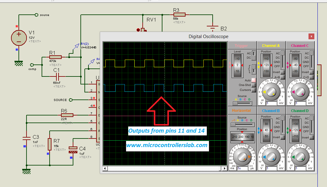
- Pins 11 and 14 are output pins. These pins provide input to MOSFETs and as I have already mentioned, there is no need to connect any Mosfet driver because sg3525 has a built-in MOSFET driver circuit.
- Pin 13 and 15 are power pins. Vc should be between 5-35 volt and Vin should be between 8-35 volt.
- Pin 16 is a reference pin and it is used to set reference voltage through pin 1 or 2. It can also be used to give 5 volts to shut down the pin in case you want to shut down sg3525 through a push-button.
Example Circuit diagram SG3524
Circuit diagrams of example below show the circuit diagram of sg3525 which generates two inverted PWM signals. Users can adjust the width of PWM using a variable resistor shown in the feedback circuit. You can change the variable resistor value to adjust the resolution of PWM.
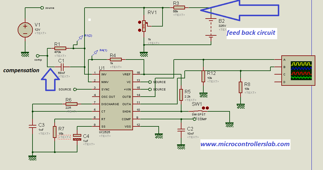
- In the above circuit diagram feedback from the output is used to get regulated voltage.
- It is discussed in detail in Dc to dc converter using a push-pull topology part.
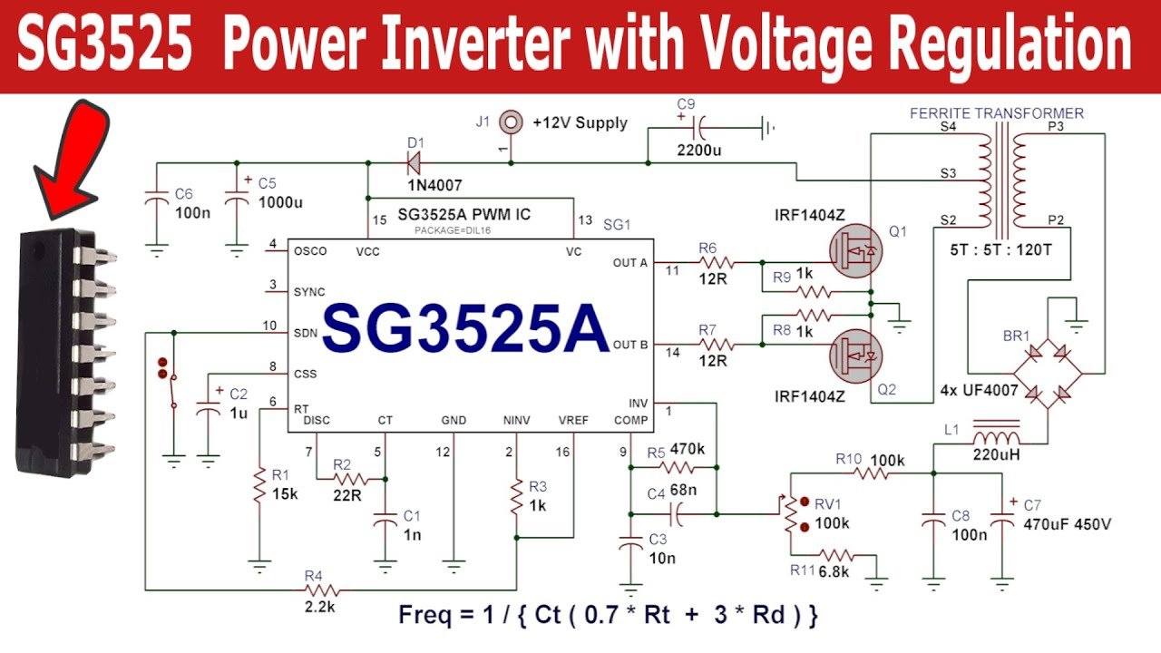
Inverter Circuit diagram Example
In this second example, this PWM controller IC is used to generate a 220 volt AC supply from 12 volts dc. This circuit is based on SG3525A which is the same IC. Two Mosfets and ferrite core transformer are used in push-pull configuration mode. This example circuit provides power regulated voltage output with the help of the feedback circuit. Variables resistor R10 provide voltage regulation feature.
SG3525 Applications
- It is used for power electronics applications like pure sine wave inverters.
- It is used to generate regulated voltage for dc to dc convert circuits like a buck converter, boost convert, cuk converter, and many others.
Other articles of pure sine wave inverter.
thank u for this circuit
could you help me for calculations of wire diameter of Ferrite transformer (ER-35) for inverter ?
50kHz
150 -200 watt
output voltage 330v of transformer
input voltage 10 -12.5
Where can I find model/library for the proteus sg3525 and how can I install it? I have been looking around, do you any info about it ? thanks
You can download library of sg3525 from google. Or post your email address here I will send you library
Please send me library of sg3525.My Email:jack.zys@gmail.com Thanks.
Send the sg 3525 Proteus
library
Please send me library of sg3525.My Emai: shraddhamaiyani0@gmail.com
You have the file? my email is
Razorbacklightning117@hotmail.com
Please send me library of sg3525 : vanmanh.94@gmail.com
HI you. i’m Sáng i’m VietNamese and i’m looking for an SG3525 modul file to add to proteus 8 library. i’m realy neeed it, plese send me this file as fast as impoble thankyou so much. my email : Vansangbk@gmail.com of my facebook: https://www.facebook.com/vansang.nguyen.3363.
once thanks alot.
kindly email me the library for proteus for sg3525 ic to skariuki91@gmail.com
plz send me liberary if u have recieved.
id: ilyas.bsee1859@iiu.edu.pk
send me the sg3525 library, thank you me email abdellah309@yahoo.fr.
Please send me library of sg3525 : ele_saeid@yahoo.com
Please send me library of sg3525. My Email: sbdada09@gmail.com Thanks for this great post
Please send me library of sg3525. My Emal : msn_fra@hotmail.com
Please send me library of sg3525.My Email:vantien1986@gmail.com Thanks.
Please send me library of sg3525.
here is may email:
mahyar6987@gmail.com
Thanks.
Please send me library of sg3525. My Email: drodayali1975@gmail.com Thanks.
Please send me library of sg3525. My Email: fjaramillo@live.com.mx
Thanks.
plz send me liberary if u have recieved.
id: ilyas.bsee1859@iiu.edu.pk
Today there is no any response. I’m also waiting for the library. Best regards
S.A.
Please send me sg 3525 library for proteus
Please send me library of sg3525. My email is:
ghaffari2000@gmail.com
Thanks
Mi email is Razorbacklightning117@hotmail.com
how to download sg 3525 in proteus 8…please help us….contact 9715807469
how to download sg 3525 in proteus 8…please help us….contact 9715807469
Did you guys win with SG3525 proteus lib I’m desperately in need of it my email address is keomoyo@gmail.com
please send me library of SG3525. my email: nguyenthanh537562@gmail.com. thanks.
guys why you all tried to easyeda software just try it online or sample version.
it will be useful and we get the SG3525 easily.
Kindly mail me SG3525 lib as well as all other libs not supplied in the proteus pack. Thank you very much in advance.
imsayuba@gamil.com
hi ,
u got the sg3525 lib file.
jdarshan25@gmail.com
Please send me library of SG3525. My Email: imdouglasandrade@gmail.com
if you got the library file … plz send it to me…
Email : 120286@students.au.edu.pk
Please send me the file at my email: aredeal15@gmail.com
I really need that for my final year project. Thank you
sir please send me library of SG3525 for proteus
sir plz send me library for sg3525 for proteus because i cant found it on google
Hello bilal
Can you send me proteus file ( LIB and IDX ) for tlp250 and SG3524
Hello sir please can you help to send me the proteus library file for sg3525 please sir my email is… abdulengaminu@gmail.com
Plz send me sg3525 library.ammarhasan90@hotmail.com
gopukrishnan222@gmail.com
nishikanta95@gnail.com
Please send me library of sg3525
Please, send me the library. Thanks.
Please send me library of sg3525 and tl494. My Email:majid.hv87@yahoo.com
Thanks
Hello sir bilal Malik
I am interested in the sg3525 component library in proteus
please send me the sg3524 proteus library
s.wadchira@gmail.com
Where can I find model / library for proteus of sg3525 ? do know how to install it ?
Thanks
sir,
any ic is available for 3 phase inverter ( ac induction motor drive) as same features like sg3525
Yes there are lot of dedicated IC’s avaialble for three phase PWM controller. Check on texas instruements website
Sir,
I am going to use the SG3525 IC for PWM of a dual stage DC-DC boost converter, and I need the duty cycle for both the MOSFETs to be 78%. However, the datasheet says that the duty cycle range is from 0 to 50% for the IC.
Can you suggest how do I get 78% duty cycle using the 3525 chip and that too without using the feedback or compensation features. Also can it drive two MOSFETs simultaneously?
Please do reply and help me out because this is my final year project.
Hi soumitra,
u got the sg3525 lib / model file for proteus.
can u please send it to my mail (allenmani93@gmail.com).
thanks
hello Soumitra
can you send me the the sg3525 lib and idx
email: nesrine-elec@hotmail.fr
Hi Bilal
please send to me SG3525 proteus model and schematics with this model.
eagle5558@gmail.com
Thank you
Hi Bilal
please send to me SG3525 proteus model and schematics with this model.
sya_eira08@yahoo.com
Thank you
please send the file for sg3524 and sg3525 in proteus
thanks
kindly send me the proteus library for sg3525 to my email skariuki91@gmail.com
please send sg 3525 library in proteus 8
please help me by sending the library sg3525 to umairzanil@gmail.com
SIR send me the library of SG3525..and how to add it ..thanks sir
sir plZ send Me library of SG3525.AND HOW TO add it ..my email address is mian.mubshir@gmail.com
SIR …CT ,RT AND SS ARE ALL VARIABLE or fixed
its depends on your requirement but maximum time it is fixed
please i need the file for sg3524 and sg3525 in proteus
i need library for sg3525 for proteus kindly help
please send the file for sg3524 and sg3525 in proteus
thanks
let me know the availability of file for SG3525.If available please send the same in order to create a lib.in proteus 8.
thanks
I need proteus 7 library file for sg3525/sg2525. My maid id is kslogu1992@gmail.com
Please send me library of sg3525.My Email is waleedusman12@yahoo.com Thanks.
Please send the sg3525 library file
My mail id is omkar.gachake@gmail.com
kindly send me the Proteus library for sg3525 to my email:
Asad1260@yahoo.com
Also tell plz how to add library??
Please send me the Proteus library for sg3525 to my email:
y.r.eduardo@gmail.com
Thanks
hey hi,
I need the component of sg3525 or Ka 3525 to add into proteus 8.
Can u please send the model file library to my email as soon as possible…
my mail id is allenmani93@gmail.com
thanks & regards
vasu.
kindly email me the sg3525 Module library for proteus for sg3525 ic to anowar,mieb26234@gmail.com
Dear Sir
would you be kind enough to mail me proteus model library of sg3525.
My mail: imsayuba@gmail.com
Thank you very much in advance !
Please send me library, my email alanjuliojesusl@gmail.com. Great
Please send me library sg3525 for proteus, my email abdellah309@yahoo.fr many thanks
Please send me library sg3525 for proteus, my email jsg2784@gmail.com
thanks
Please send me library of sg3525a.My Email is pongdanaikamsandech@yahoo.com Thanks.
Hello Mr. Bilal. I tried this circuit in practice in H bridge configuration (12V supply and operating at 50z, a resistive load of 3.2k )but the problem is two of my mosfets (one from either set;IRF540) are getting hot like hell while the other two are warm. The output voltage is about 1V only. I cant figure out the problem. Is my mosfet not properly switching ? please help. IF u can please send the model of sg3525 for proteus to the following mail id:
ID: tathagatabiswas9@gmail.com
Hello!
What’s the sawtooth peak voltage generated by the sg3525? I need this information in order to close the loop of a CC-CC converter.
Please send me the library of SG3525. My email is klosowsk@gmail.com.
Thanks very much!
Please send me library of sg3525a. My Email is josavidaljr@gmail.com Thanks.
please send me library of sg3525.my email is rashedulhasan178@gmail.com thanks
hi Bilal, can you please email me SG3525 library for proteus. Thanks in advance.
plz send me library if sg3525 .my email rashedulhasan178@gmail.com thanks
hi Bilal, can you please email me SG3525 library for proteus. My email is bilalabid777@gmail.com. Thanks in advance.
please, send the proteus library for sg3525/2525 to me.
thanks.
oluwaseun00791@yahoo.com
library is not for free. you can purchase it in 3$ check at the end of article.
please send the proteus library for sg3525AJ/2525, and ka3525.
thanks.
sumreen.j@hotmail.com
hello…..
kindly help me how to add library of SG3525A in proteus Professional 7.
email me scorpiongull@gmail.com
hello…..
kindly help me how to add library of SG3525A in proteus Professional 8.
email me Andrew-m.soree@hotmailmail.com
hi.
i am baber khan
plz sent my protious labrary for ka3525 or sg3525.
bk07278@gmail.com
charsadda, pakistan
Please send me library of sg3525 or sg3524.My Email:sonirahul1605@gmail.com
Thanks.
Please send me library of sg3525 or sg3524.My Email:neiliyassin339@gmail.com
Thanks.
hey please mail me the proteus library of sg3525.
Email: ankitsingh.rs@gmail.com
Please send me library of sg3525
My Email:eduardo.zequim@gmail.com
Thanks.
salam Bilal Sir,
I need the component of sg3525 or Ka 3525 to add into proteus
Can u please send the model file library to my email as soon as possible.
sameedahmedkhan94@gmail.com
please send me the library in my gmail SG3525 I thank (ducchung48@gmail.com)
Please send me library sg3525 for proteus, my email amrithacn4@gmail.com
Please send me library of sg3525.My Emai: risantoe@gmail.com
Please send me library of sg3525 or sg3524.My Email:j434caramello@gmail.com
Thanks.
Hi, Sir please send me library of sg3525
Hai sir i need a circuit using SG3525 with igbt drives…for the ratinv below
I/p- 415v
O/p- 12v/300A dc
Please send me library of sg3525 or sg3524.My Email:Chaiwat5204@gmail.com
Thanks.
Please send me library of sg3525 or sg3524.My Email: Chaiwat5204@gmail.com
Thanks.
Please send me library of sg3525., it will be a great help for Me My Email: adeniyijamesa@gmail.com Thanks for this post
can you give me detail about how to add this file in the library
Buen día, muy buen post, por favor podrias enviarme la libreria del SG 3525, me sería de mucha ayuda.
Mi correo es marcosuarez982@gmail.com. Gracias
assalam o alaium brother kindly send me the proteus library for sg3525 and schematic
to my email ch.shahid.official@gmail.com
Please send me library of sg3525a. My Email is sambanthamsekar34@gmail.com. Thanks
please send me too library of sg3525 and scematic to my email
s1617hp@gmail.com
thanks
Hello!
i need schematic sawtooth generated
Please send me of sawtooth generator. My email is liardipratama11@gmail.com.
Thanks very much!
Please send me library of sg3525 or sg3524.My Email: mustafayetgin7@gmail.com
Thanks.
Please send me library of sg3525 or sg3524.My Email lequochung99@gmail.com
thank so much
HUng
you can find library here
http://store.microcontrollerslab.com/product/sg3525-proteus-library/
i need Proteus library for SG3525.
sheri_skt@hotmail.com
Thanky you.
Good day Sir , please I need that library for SG3525 and thanks for the post
My email adeniyijamea@gmail.com thanks
Sir my question is why you use SG3525 IC why not you produce PWM from the microcontroller? For pure sine wave inverter, you have used microcontroller for AC output. Why don’t you program microcontroller to get PWM? It really helps if you answer me.
Thank You
Sir, can you send me the library of SG3525 for Proteus?
My email: ndrasanaljd@gmail.com
Sir pls send me the library for sg3525 or sg3524n for proteus. Thanks
Danieloluwole51@yahoo.com
Hi
Please send me library of sg3525.
Thanks.
Please send me library of sg 3525
email : rochmadnur97@gmail.com
Hi
Please send me library of sg3525.
Thanks.
email:saeid.mohebbi33@yahoo.com
Please send me the Proteus library for sg3525 to my email:
irijahebe@gmail.com
I’d be really greatfull.
Thanks
Hi sir, hope you are good. i need sg3525 proteus library. email id is “adreeskhan1995@gmail.com ”
thanks.
Please send me the Proteus library for sg3525 to my email:
watigana@gmail.com
ASSALAM U ALAIKUM I NEED SG3525 LIBRARY, CAN YOU SEND NE PLEASE.
MY EMAIL ADDRESS IS:
memonbilal.121@gmail.com
can u send me sg 3525 library on email nilesh.topale@gmail.com
Please Engr Malik, can you send me the SG3525 simulation model for Proteus
My email is: mcmdroidsmart@gmail.com
Thanks.
Pls can someone send me the shoes 3525 lib on my email
Thanks
can anyone send me the sg3525 simulation for proteus? it will help me a lot. thanks!
Hello sir, Thanks for this tutorial.I’m building PWM invertor using KA3525A by Using Eagle Software.Circuit I have done but to do simulation .mdl extension file is not avaliable for KA3525A IC.
Can anyone please provide the model extension file of KA3525A .my mail id is meghamn73@gmail.com
one more question does SG3525A IC is same as KA3525A IC ?
u got the sg3525 lib / model file for proteus.
can u please send it to my mail (ibrahim@kktmpmas.edu.my).
thanks you sir
Please send me library of sg3525.My Emai:
Hello
Please send me the Proteus library for sg3525 to my email
Hello
Please send me the Proteus library for sg3525 to my email
Sir i want to make a dc to dc converter for car amplifier.
By using 50khz frequency i will not get sufficient current so i wand to reduce it to 20khz . And i need 200w power at output
Can you please send me a circuit of pwm using sg3525 ic of frequency 20khz ?
And if you don’t mind , i want some advice from you that hot how can i make perfect supply for the amplifier , and which diode will give good response on this frequency . Thank you sir
Sir can i used this inverter for high volt solar system like 300-400 dc Solar volt
i’ll would like to know how do we calculate the value of CT and RT for SG2524
Pulse-Width Modulator
Hello,
Please send me the Proteus library for sg3525 to my email, pedro.vargas@uaem.mx, thks.
Hello 🙂
Please send me the Proteus library for sg3525 to my email:
buysahome@vp.pl
Thanks
please give me proteus library.munnakumar354@gmail.com
Please send library sg3525
Hello sir please can you send me the protues library of sg3525
pls I need the sg3524 library
send to chidubempaul91@gmail.com
pls I need the sg3524 library
pls pls pls pls
ogun4bambo@gmail.com
can you send me the library for SG3525 please help me ASAP
amoslih_1987@hotmail.com
can you send me the library for SG3525 and TL494 please help me ASAP for proteus 8.8 and 7
anil31.vishwakarma@outlook.com
Can you send me the library for SG3525 please help me.
kaganayanoglu@gmail.com
can you send me the library for SG3525 and TL494 please help me ASAP for proteus here drijsoh@gmail.com
please help me sir, can you send me library of ic SG3525?
this is my email angg4.nr@gmail.com
HI
can you send me the library for SG3525 and TL494 please help me ASAP for proteus 8.8 and 8.9
thanks my love
my email abdalrhem_2010@yaoo.com
I really need the sg3525 library for proteus8.if you can give me this library! thank you email: tanaview@gmail.com
Hello is there a option to increase the duty cycle of 49% to 98% of the sg3525?
thank you!
can you send me the library for SG3525 and TL494 please help me ASAP for proteus 8.8 and 7
How to synchronize the two SG3525. Give me a tip please I intend to use one at high frequency 24KHz and the other at low 100Hz. If anyone can help me, I will be very grateful.
Thank you.
just pulse the sync input with a very short pulse. do you need to sync the 24KHz to the 100 Hz?
Dear sir
We want to purchase 3 phase sine wave Grid sync Inverter Circuit with Coding etc.
kindly Help.
Thank you.
can you send me the library for SG3525 and TL494 please help me ASAP for proteus 8.8 and 7
Dear sir
please i would like to know how to get 5ohz oscillation from the ic 3525.I calculated the circuit above from the formula and didnt get 50hz. Please help me out, Thank you.
According to the datasheet (KA3525A), guaranteed frequency starts from 120Hz and typically you can expect only down to 60Hz, so it seems you are out of luck with your particular chip or the real cap value within tolerance range (can be as bad as -80% for e.g. some SMD MLCC types) wasn’t verified.
Dear Sir,
Could you pls send me or publish the driver for UC2525 which you have used in this article.
Thanks with regards
Gamini
Can I use 3524 ic against of 3525 ic for inveter can u tell me both above two ic are similar or not
IM making Capacitive Discharge Ignition for my bike . but when i discharge the capacitor to ground with scr the output supply also grounded . can i shutdown the ic by giving positive pulse on shutdown pin. my working frequecy for shutdown the ic could be 250Hz. is there any effect on ic or it takes time to shut down
Hello sir im trying to connect the synchro of 100KHZ on pin 3 of the sg3525 i have A default frequency and periodic cycle! can i possibly send you a email to have your opinion on it?
thank you for helping us understanding this ic!
Hi sir. Please to send me SG3525 proteus library. I use proteus 8.8.
Hi sir. Please to send me SG3525 proteus library. I use proteus 8.8
Please send me the Proteus library of uc3525
Can you share with me SG3525 library ?
Please send me the Proteus library of uc3525
SURCH UC3525 IN PROTEUS
Hello – I wish to use SG3525 in power inverter application similar as shown with a rectified output of about 300vdc. I do not need voltage regulation, but do need to current limit the rectified output so that the supply can rapidly accommodate being shorted to ground and limit output current to under 20ma. When the short is removed, it should immediately resume function. Can this be accomplished by feedback to the controller, or should it be in the transformer design?