Recommended Components
The following parts are used in this article, along with a generic electronics kit that is handy for building and testing the circuit.
| Component | How it’s used | Buy on Amazon |
|---|---|---|
| SG3524 (SG2524) PWM controller | An SG3524 PWM controller — the commercial-grade equivalent of the SG2524 this article covers. | Check Price |
| Electronic component assortment kit (1390 pcs) | A handy assortment of resistors, capacitors, LEDs, diodes and transistors for building circuits. | Check Price |
| Digital multimeter (AstroAI) | Measures voltage, current, resistance and checks continuity while you build and debug. | Check Price |
| Breadboard | Solderless base for prototyping the circuit. | Check Price |
| Jumper Wires | Make the connections on the breadboard. | Check Price |
As an Amazon Associate we earn from qualifying purchases. Prices and availability are accurate as of the date/time indicated and are subject to change.
SG2524 Pinout Diagram
This PWM controller IC has sixteen pins. The pinout diagram presents an obvious feature of each pin. But you can read a description of each pin in the next section.
Pin Configuration Details
The IC SG2524 has total of of 16 pins. All the pins along with their functionalities are described in the table given below:| Pin Number | Pin Name | Description |
|---|---|---|
| 1, 2 | IN-, IN+ | Negative and Positive input of error amplifier |
| 3 | OSC OUT | Output of the Oscillator |
| 4, 5 | CURR LIM+, CURR LIM- | Positive and negative input of current-limiting sense amplifier |
| 6, 7 | RT, CT | Frequency of a regulator is programmed by RT and CT. |
| 8 | GND | Ground of the circuit |
| 9 | COMP | Compensation pin of error amplifier |
| 10 | SHUTDOWN | If shut down pin is LOW, the circuit will work but if it is HIGH, the IC will remain in the shutdown mode. |
| 11, 14 | EMIT 1, EMIT 2 | Emitter terminal of BJT 1 and BJT 2. These are output pins. |
| 12, 13 | COL 1, COL 2 | The collector terminal of BJT 1 and BJT 2. These are output pins. |
| 15 | Vcc | Positive power supply |
| 16 | REF OUT | Output pin of reference regulator |
SG2524 Features
- Pulse width modulator whose operation is specified in a voltage range of 8V to 40V
- Single-ended or push-pull outputs
- Total supply current is less than 10mA
- Standby current= 8mA
- typical operation up to 300khz
- Maximum Duty cycle is 45 %
- Shut down capability
- Maximum power dissipation= 1000mW
Equivalents
SG3525, SG3524Alternative options
Where to use it?
It is a 16-pin integrated IC which can be used in applications requiring high power at the output. These IC’s are widely used in controlling the speed of DC motors, communication systems, power conversion control circuits, and instrumentation. We can also use it in designing dual polarity for switching regulators and dc-to-dc converters. You can use this IC in an application whose operation is based on switching signals and turning the devices like Mosfets On and OFF.How to use SG2524 PWM Controller?
How to set Frequency?
The IC contains the voltage-controlled circuit. The frequency of the regulator is controlled by an external timing capacitor and timing resistor connected to pin 6 and pin 7 of the IC. RT and CT generate frequency with the constant time charge current of CT. The timing capacitor and resistor combination produce a linear ramp voltage. By comparing linear ramp voltage with a comparator, we get an output pulse of PWM.F = 1.30 / RT x CT
Example Test Circuit
The general test circuit is shown in the figure below. This IC contains an internal regulator of 5V which acts as a reference and is used to supply the internal control circuitry of the regulator. Pin 10 is a shut-down pin which protects the circuit from damages for example over voltage or current by shutting down the IC.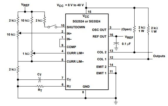 It consists of two BJT’s with uncommitted collectors and emitters output and anti-saturation circuitry. This anti-saturation circuit limits the current to a maximum of 100 mA for fast response. Pin 8 and 15 are connected to the ground and positive power supply. Pin 9 is used to control the voltage fed back from the inverter output to the error amplifier. It is basically used to adjust the output voltage of the inverters. If the voltage on pin1 is greater than the voltage on pin 2, the duty cycle increases and vice versa.
SG2524 Applications
This IC has numerous applications. Some of them include:- Transformer-coupled DC/DC converters
- Switching-regulators of any polarity
- Voltage doublers
- Used in applications employing fixed-frequency, pulse-width modulation (PWM) techniques to perform polarity conversions
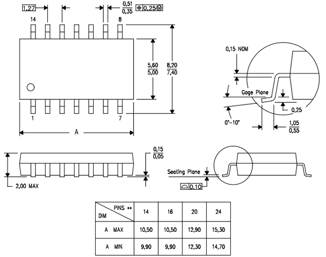
2D Diagram
Sg2524 two-dimension diagram needs to design a PCB.