MG995 Servo Motor is a heavy-duty reliable servo motor. It is a low-power, cost-effective motor. MG995 is a dual shock-proof ball-bearing servo design with metal gear making it quite feasible for industrial production. The motor has a quick response and rotates at high speed. It comes with great holding power and a stable constant torque range. They are widely used in consumer robotics and hobby projects. This post is an overview of the motor and discusses the pinout, features, working, interfacing with Arduino, and applications of MG995.

Recommended Components
The following components are used in this project or are helpful for building it with the Arduino.
| Component | How it’s used in this project | Buy on Amazon |
|---|---|---|
| Arduino Uno R3 | The main microcontroller board that runs the sketch and reads the sensors/modules in this project. | Check Price |
| Breadboard | Lets you wire the components to the Arduino without soldering for quick prototyping. | Check Price |
| Jumper Wires | Connect the Arduino pins to the module and other parts on the breadboard. | Check Price |
| Servo motor (SG90) | A hobby servo controlled by the Arduino PWM signal (MG995 in the guide). | Check Price |
As an Amazon Associate we earn from qualifying purchases. Prices and availability are accurate as of the date/time indicated and are subject to change.
MG995 Servo Motor Pinout
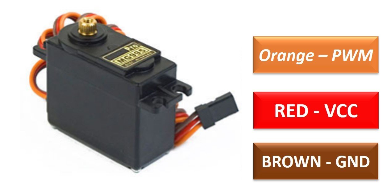
MG995 is a durable double ball bearing servo motor. The diagram shown below is the pinout of the MG995 Servo Motor:
MG995 Pin Configuration
It is a three terminal device.The pin configuration detail in tabular is mentioned below:
| Pin Color | Pin Name | Function |
|---|---|---|
| Red | VCC | Positive Power Supply pin |
| Brown | GND | Reference Potential pin – Connect to the ground of power supply |
| Orange | PWM Signal | Pulse width modulation input pin that is used to control the axis of rotation of MG995 servo motor |
MG995 Features and Specifications
- Operating Voltage: 4.8 – 7.2 Volts
- Operating Temperature: 0 – 550C
- Operational Frequency: 50 Hz
- Operating Motor Speed @ 4.8 V: 0.2 sec/60 degrees
- Operating Motor Speed @ 6 V: 0.16 sec/60 degrees
- Motor Stall torque @ 4.8 V: 8.5 kgf·cm
- Motor Stall torque @ 6.0 V:10 kgf·cm
- Dead band width: 5 usec
- Degree of Rotation: 180 degrees
- Idle state Current consumption: 10 mA
- No Load Current Consumption: 170 mA
- Maximum Load Current Consumption: 1200 mA
- Physical Dimensions: 40.7 x 19.7 x 42.9 mm approx
How to use MG995 Servo Motor
The motor is energized using the power pins that are VCC and GND. The MG995 Servo motor has a signal input pin to rotate the motor. The working principle of this motor is pulse width modulation. The concerned Servo motor can operate only at 50 MHz of frequency. Any value more or less leads to malfunctioning of the device. That is why each cycle of the PWM signal is of 20 milliseconds.

The position of the axis of the motor depends on the duty cycle of the signal. There are some standard calculations for degree rotation. If the PWM signal is high for 0.5ms in a single cycle, the axis moves to zero degrees. To rotate the motor axis to 90 degrees, the signal should be high for 1.5ms. Similarly, a 2.5ms ON-time signal leads to 180-degree axial position.
In this way, we can measure and control our motor to desired degrees. To keep things convenient, specific libraries are written to control and interface the motor instead of setting the PWM values every single time.
Interfacing MG995 Servo Motor to Arduino UNO
In this section, we will learn to interface SG995 servo motor with Arduino. We will use Arduino uno in this tutorial, but you can use any Arduino board which provides at least one PWM signal output. Moreover, almost all Arduino board provides PWM signal.
Connection Diagram
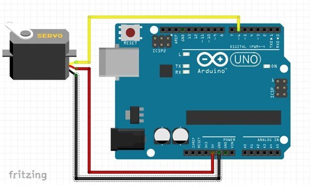
- Connect the power voltage pins of the MG995 Servo motor to the 5 Volts pin and the GND pin of the Arduino UNO. This will energize the motor.
- Connect the PWM input pin of the motor to the Arduino PWM output pin D6 to control and rotate the motor.
| Arduino UNO | MG995 Servo Motor |
|---|---|
| 5V | VCC |
| GND | GND |
| D6 | PWM pin |
The wiring diagram to show the connections is provided below:
Arduino Code
Here is a small example code to brief the use of this motor practically.
/* This example Arduino Sketch controls the complete rotation of
 *  SG995 Servo motor by using its PWM and Pulse width modulation technique
 */

#include <Servo.h> // include servo library to use its related functions
#define Servo_PWM 6 // A descriptive name for D6 pin of Arduino to provide PWM signal
Servo MG995_Servo;  // Define an instance of of Servo with the name of "MG995_Servo"


void setup() {
  Serial.begin(9600); // Initialize UART with 9600 Baud rate
  MG995_Servo.attach(Servo_PWM);  // Connect D6 of Arduino with PWM signal pin of servo motor

}

void loop() {
  Serial.println("0");// You can display on the serial the signal value
  MG995_Servo.write(0); //Turn clockwise at high speed
  delay(3000);
  MG995_Servo.detach();//Stop. You can use deatch function or use write(x), as x is the middle of 0-180 which is 90, but some lack of precision may change this value
  delay(2000);
  MG995_Servo.attach(Servo_PWM);//Always use attach function after detach to re-connect your servo with the board
  Serial.println("0");//Turn left high speed
  MG995_Servo.write(180);
  delay(3000);
  MG995_Servo.detach();//Stop
  delay(2000);
  MG995_Servo.attach(Servo_PWM);


}
Code Explanation
Library Installation & Pin Declaration: For easy interfacing, install the servo motor library i.e “Servo.h”. Then restart the Arduino IDE software and include it into the sketch. Next is defining the pin. We have connected the signal pin of the motor to the PWM pin 6 of Arduino. Furthermore, create an instance MG995_Servo of the servo library functions.
/* This example Arduino Sketch controls the complete rotation of
 *  SG995 Servo motor by using its PWM and Pulse width modulation technique
 */

#include <Servo.h> // include servo library to use its related functions
#define Servo_PWM 6 // A descriptive name for D6 pin of Arduino to provide PWM signal
Servo MG995_Servo;  // Define an instance of of Servo with the name of "MG995_Servo"
void setup: The void setup section initializes the Serial communication with the standard baud rate of 9600 bps. It also attaches the MG995_Servo instance to pin 6.
void setup() {
  Serial.begin(9600); // Initialize UART with 9600 Baud rate
  MG995_Servo.attach(Servo_PWM);  // Connect D6 of Arduino with PWM signal pin of servo motor

}
void loop: The loop section is coded to rotate the motor clockwise first and then anticlockwise. When the myservowrite(0) is executed, the motor starts rotating from the right side for some time and then stops for 2000 milliseconds. Also detaches the instance to reduce motor noise. Similarly, when myservowrite(180) is executed, the motor rotates in an anticlockwise direction again halts for 2000 milliseconds.
void loop() {
  Serial.println("0");// You can display on the serial the signal value
  MG995_Servo.write(0); //Turn clockwise at high speed
  delay(3000);
  MG995_Servo.detach();//Stop. You can use deatch function or use write(x), as x is the middle of 0-180 which is 90, but some lack of precision may change this value
  delay(2000);
  MG995_Servo.attach(Servo_PWM);//Always use attach function after detach to re-connect your servo with the board
  Serial.println("0");//Turn left high speed
  MG995_Servo.write(180);
  delay(3000);
  MG995_Servo.detach();//Stop
  delay(2000);
  MG995_Servo.attach(Servo_PWM);


}
Applications
- Toy planes
- Robotics
- Industrial equipment
- DIY projects
- Drones
- Telescopes
2D Diagram

- SG-90 Servo Motor Interfacing with TM4C123 Launchpad
- ESP32 Web Server Control Servo motor with Arduino IDE
- SERVO MOTOR interfacing with PIC16F877A MICROCONTROLLER
- Web Controlled Servo Motor using Arduino and esp8266
- servo motor interfacing with 8051 using Keil compiler
- joystick based servo motor control using Arduino
- Servo motor control and interfacing with Arduino
Can it rotate 90 degrees?
how do I control multiple MG995 servo’s with the Arduino UNO or MEGA