This tutorial is about DC motor interfacing with TM4C123 Launchpad. We will learn to control the speed of a DC motor using a pulse width modulation module (PWM) of TM4C123 and L298N motor driver modules. Furthermore, we will also control the direction of rotation of a motor using the built-in H-bridge of L298N and GPIO pins of TM4C123 microcontroller. We will use Keil uvision to write a program and upload code to Tiva Launchpad.

Recommended Components
The following components are used in this project or are helpful for getting started with TM4C123 Tiva C LaunchPad development.
| Component | How it’s used in this project | Buy on Amazon |
|---|---|---|
| TM4C123G Tiva C LaunchPad | The Tiva C board generating the PWM and direction signals. | Check Price |
| Micro USB Cable | Connects the LaunchPad’s onboard debugger to your PC for programming and power. | Check Price |
| DC Motor | The hobby DC motor whose speed and direction are controlled. | Check Price |
| L298N Motor Driver | H-bridge driver that powers the motor from the TM4C123 signals. | Check Price |
| Breadboard | Solderless breadboard for building the circuit. | Check Price |
| Jumper Wires | For wiring the motor, driver and LaunchPad together. | Check Price |
As an Amazon Associate we earn from qualifying purchases. Prices and availability are accurate as of the date/time indicated and are subject to change.
DC Motor Introduction
DC motors are electro-mechanical machines which convert electrical energy into mechanical (rotational) energy. If you are looking to develop a robot such as a line follower robot, obstacle avoidance robot, these DC motors will be the first choice for you. They are available in direct drive or geared types. But, both types require a dc voltage to operate. Therefore, we apply a DC voltage to drive DC motors.
Speed Control
The speed of rotation of motors is directly related to the input voltage. The higher the input voltage, the higher will be the rotational speed of the motor. But the voltage should be within the operating voltage range.
One important point to note here is that if we want to control the speed of a DC motor, we will need to provide a variable voltage to the DC motor. For example, If the operating voltage range of a motor is between 3 – 6 volts. If we apply 3 volts input, the motor will run at its lowest rated speed. Similarly, if we apply 6 volts, the DC motor will run at its highest rated speed. In short, we can control the speed of rotation by giving a variable input voltage to a DC motor. Usually, a pulse width modulation technique is used to generate a variable dc voltage from constant dc voltage source. We will discuss it in later sections of this tutorial.
Direction Control
As you know that in case of DC power supply, there is a concept of polarity such as positive and negative terminals of a battery. The polarity of input voltage source determines the direction of rotation of a DC motor. For instance, if we connect the positive terminal of battery with one terminal and the negative terminal of battery with another terminal of DC motor, it will start rotating in clockwise direction. But if we interchange the connection of the battery by connecting opposite polarity, the DC motor will start rotating in another direction as shown in the simulation below.
Generally, an H-Bridge circuit is used to provide opposite polarity power to a DC motor without changing actual power supply connections. An H-Bridge consists of four switches, resistors, and two control signals as shown in the figure. Two logic probes control the direction of a DC motor. When left probe logic signal is on, the motor rotates in an anti-clockwise direction and when right probe logic signal is on, the motor rotates in a clockwise direction.

We will discuss it in later parts of this DC motor interfacing with the TM4C123 tutorial.
9V DC Motor
In this tutorial, we will use a hobby DC motor as shown in the figure below. It consists of two terminals such as terminal_1 and terminal_2. There is no concept of marked polarity in this motor. Because these two terminals are internally connected through a single coil. Therefore, we can reverse the direction of the motor by applying opposite polarity to these terminals.
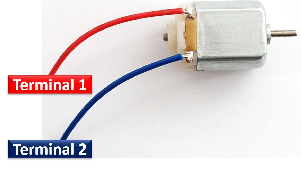
The operating voltage of this toy motor is 4.5 to 9 volts. Hence, by applying a variable voltage between 4.5-9 volts, we can control its speed.
L298N Motor Driver Introduction
L298N motor driver shield consists of an L298 motor driver IC, 7805 voltage regulators, pinouts to provide input signals from microcontrollers, and pins to connect two DC motors.
It consists of two H-Bridge circuits to drive two separate DC motors. On top of that each H-Bridge has an enable pin which is used to provide ON/OFF signal. But we can also use Enable pins to provide PWM signal to each DC motor.
The following figure provides the details of all motor driver components:
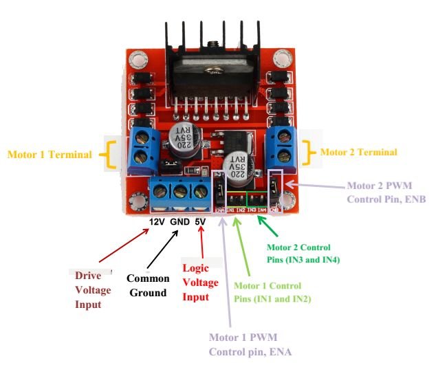
There are two terminals two connection two DC motors.
- IN1 and IN2 are Motor_1 direction control pins of internal H-Bridge. Similarly, IN3 and IN4 are Motor_2 direction control pins of the second internal H-Bridge of the L298N motor driver.
- ENA and ENB control motor_1 and motor_2 respectively. Keeping these pin logic high will let the DC motors rotate. On the contrary, pulling these pins to an active low state will turn off the motors. But by removing jumpers, we can apply a PWM signal to each pin instead of just an ON/OFF signal.
Speed Control with L298N and TM4C123
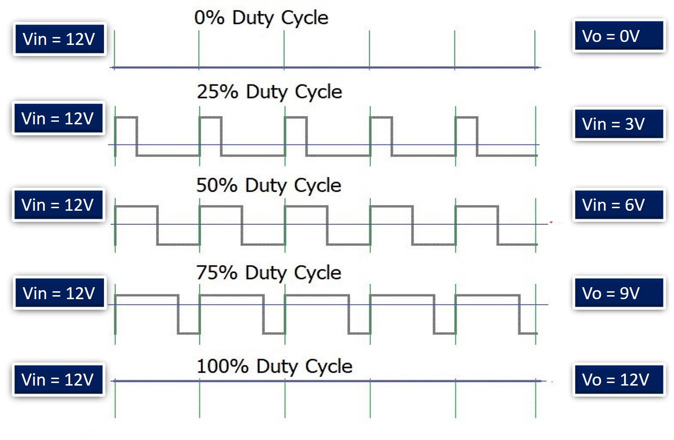
As we discussed earlier, the speed of a DC motor is directly proportional to the applied input voltage. But DC voltage is generally applied to a DC motor from a constant voltage source such as battery or adapter. Therefore, we use a special technique known as pulse width modulation to get variable output voltage from a constant DC voltage source.
In a PWM method, we apply the DC voltage to a DC motor through a series of on-off pulses which control the voltage magnitude appearing across motor terminals. The duty cycle or on-time of these pulses determines the average voltage which appears across motor terminals. Higher the duty cycle, higher will be the average output voltage. The lower the duty cycle, the lower will be the average voltage across a motor.
The following figure depicts the relationship between output and input voltage according to the duty cycle of PWM pulses.
TM4C123 PWM Pins
As you know that TM4C123 Tiva Launchpad comes with a TM4C123GH6PM microcontroller. This microcontroller has 8 built-in PWM generators. These PWM generators can be used to generate variable duty cycle PWM signals. In response, we can use these variable duty cycle PWM signals from TM4C123 to get variable DC voltage and ultimately to control the speed of a DC motor.
We will feed the TM4C123 PWM signal to enable the pin (EnA or EnB) of the L298N motor provide to provide variable DC voltage to the DC motor.
You can read about our previously posted in-depth guide on TM4C123 PWM:
DC Motor Interfacing with TM4C123 Tiva Launchpad
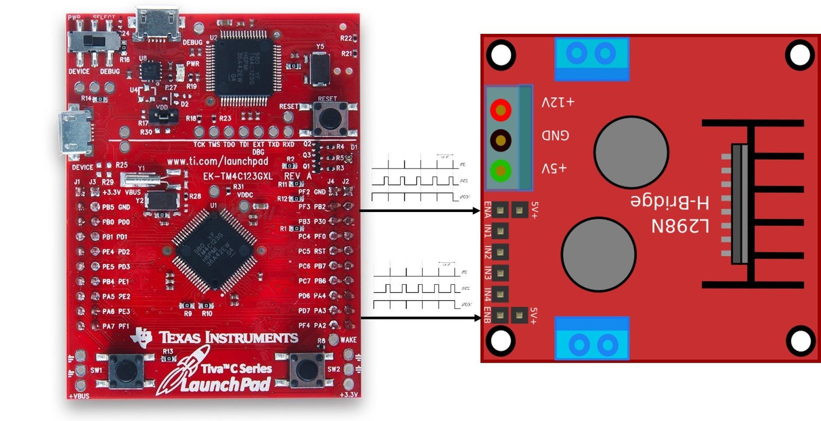
To interface a DC motor with TM4C123 through the L298N motor driver, we need to provide three signals to the L298N motor driver from TM4C123 GPIO pins. Two signals to control the direction and one PWM signal. To control direction, we just provide an active HIGH/LOW signal to L298N. Therefore, we can use two GPIO pins of TM4C123 as digital output pins.
As discussed earlier, TM4C123 microcontroller have 8 PWM generators. We can use any PWM generator of TM4C123 to provide a PWM signal.
Connection Diagram
Now make the connections with TM4C123, L298N, and DC motor according to this schematic diagram. In this example, we use PA2 and PA3 pins of TM4C123 to provide IN1 and IN2 control signals to the motor driver. Because we are using only one motor in this tutorial.

To provide a PWM signal to Arduino, we will use the PWM1 module and its channel 6 to generate the PWM signal. This channel provides PWM output on the PF2 pin of TM4C123. Hence, we connect the PF2 pin to the ENA pin of L298N.
For a power supply, connect 5 volt and 12-volt sources to respective terminals of TM4C123. Also, make sure to common ground terminals of all modules and power supplies.
Code
This code rotates the motor in both directions, starting from the lowest speed to the highest speed. That means first we apply the lowest possible duty cycle to EnA pin of L298N. After that gradually increase the duty cycle from low to high value. In a similar order, the speed of the dc motor also increases.
If you are just getting started with ARM programming, you can check these Keil getting started guides:
- How to download and install Keil uVision for ARM and 8051
- Getting started with Keil uVision: Write your first Program for Tiva LaunchPad
/* This program controls the direction and speed of DC motor using PWM and L298N Motor driver */

#include "TM4C123GH6PM.h"
void Delay_ms(int time_ms);
int duty_cycle = 4999;
void PWM_init(void);
void Turn_OtherDirection(void);
void Turn_oneDirection(void);
int main(void)
{

    	  PWM_init();
        Turn_oneDirection();
    for(;;)
    {
        duty_cycle = duty_cycle - 10;
        if (duty_cycle <= 0)
				duty_cycle = 5000;
        PWM1->_3_CMPA = duty_cycle;
        Delay_ms(100);
    }
}


//Spin motor in one direction by giving IN1 and IN2 signals to L298N
void Turn_oneDirection(void)
{
SYSCTL->RCGCGPIO |= 0x01;   /* enable clock to PORTF */
	   GPIOA->DIR |= (1<<3)|(1<<2);            /* pin digital */
     GPIOA->DEN |= (1<<3)|(1<<2);            /* pin digital */
     GPIOA->DATA |=(1<<2);
		 GPIOA->DATA &=~(1<<3);
}

//Spin motor in other direction by giving IN1 and IN2 signals to L298N

void Turn_OtherDirection(void)
{
SYSCTL->RCGCGPIO |= 0x01;   /* enable clock to PORTF */
	   GPIOA->DIR |= (1<<3)|(1<<2);            /* pin digital */
     GPIOA->DEN |= (1<<3)|(1<<2);            /* pin digital */
     GPIOA->DATA |=(1<<3);
		 GPIOA->DATA &=~(1<<2);
}
void PWM_init(void)
{

     /* Clock setting for PWM and GPIO PORT */
    SYSCTL->RCGCPWM |= 2;       /* Enable clock to PWM1 module */
    SYSCTL->RCGCGPIO |= 0x20;  /* Enable system clock to PORTF */
	  SYSCTL->RCC |= (1<<20);    /* Enable System Clock Divisor function  */
    SYSCTL->RCC |= 0x000E0000; /* Use pre-divider valur of 64 and after that feed clock to PWM1 module*/

 /* Setting of PF2 pin for M1PWM6 channel output pin */
   	GPIOF->AFSEL |= (1<<2);          /* PF2 sets a alternate function */
    GPIOF->PCTL &= ~0x00000F00; /*set PF2 as output pin */
    GPIOF->PCTL |= 0x00000500; /* make PF2 PWM output pin */
    GPIOF->DEN |= (1<<2);          /* set PF2 as a digital pin */

    PWM1->_3_CTL &= ~(1<<0);   /* Disable Generator 3 counter */
	  PWM1->_3_CTL &= ~(1<<1);   /* select down count mode of counter 3*/
    PWM1->_3_GENA = 0x0000008C;  /* Set PWM output when counter reloaded and clear when matches PWMCMPA */
    PWM1->_3_LOAD = 5000;     /* set load value for 50Hz 16MHz/64 = 250kHz and (250KHz/5000) */
    PWM1->_3_CMPA = 4999;     /* set duty cyle to to minumum value*/
    PWM1->_3_CTL = 1;           /* Enable Generator 3 counter */
    PWM1->ENABLE = 0x40;      /* Enable PWM1 channel 6 output */
}
/* This function generates delay in ms */
/* calculations are based on 16MHz system clock frequency */

void Delay_ms(int time_ms)
{
    int i, j;
    for(i = 0 ; i < time_ms; i++)
        for(j = 0; j < 3180; j++)
            {}  /* excute NOP for 1ms */
}
void SystemInit(void)
{
    /* use this only if you are using old versions of Keil uvision */
    SCB->CPACR |= 0x00f00000;
}
How Does Code Work?
Here’s a breakdown of the code that controls the speed and direction of a DC motor using PWM and the L298N motor driver with the TM4C123 microcontroller:
Header Files
#include "TM4C123GH6PM.h"This includes the device-specific header file for the TM4C123 microcontroller, which provides access to all the registers.
Function Prototypes
void Delay_ms(int time_ms);
void PWM_init(void);
void Turn_OtherDirection(void);
void Turn_oneDirection(void);
These are function prototypes for the delay function, PWM initialization, and motor direction control.
Global Variables
int duty_cycle = 4999;duty_cycle controls the PWM duty cycle. The value can range between 0 and 5000 (corresponding to a 0% to 100% duty cycle).
Main Function
int main(void)
{
    PWM_init();             // Initialize PWM
    Turn_oneDirection();     // Set motor to rotate in one direction
    for(;;)
    {
        duty_cycle = duty_cycle - 10;   // Decrease the duty cycle to reduce speed
        if (duty_cycle <= 0)
            duty_cycle = 5000;          // Reset duty cycle if it reaches 0
        PWM1->_3_CMPA = duty_cycle;     // Update PWM duty cycle
        Delay_ms(100);                  // Delay for 100 ms between each step
    }
}- PWM_init(): Initializes the PWM for controlling motor speed.
- Turn_oneDirection(): Sets the motor to rotate in one direction.
- for(;;): Infinite loop that decreases the duty cycle (speed) gradually. Once the duty cycle reaches 0, it resets to 5000 to start the process over. The
PWM1->_3_CMPAregister updates the duty cycle, affecting motor speed.
Motor Direction Control
Turn Motor in One Direction
void Turn_oneDirection(void)
{
    SYSCTL->RCGCGPIO |= 0x01;   // Enable clock to PORTA
    GPIOA->DIR |= (1<<3)|(1<<2); // Set PA2 and PA3 as output pins
    GPIOA->DEN |= (1<<3)|(1<<2); // Enable digital functionality for PA2 and PA3
    GPIOA->DATA |=(1<<2);        // Set PA2 HIGH
    GPIOA->DATA &=~(1<<3);       // Set PA3 LOW
}- Sets PA2 HIGH and PA3 LOW, which spins the motor in one direction using the L298N driver.
Turn Motor in Other Direction
void Turn_OtherDirection(void)
{
    SYSCTL->RCGCGPIO |= 0x01;   // Enable clock to PORTA
    GPIOA->DIR |= (1<<3)|(1<<2); // Set PA2 and PA3 as output pins
    GPIOA->DEN |= (1<<3)|(1<<2); // Enable digital functionality for PA2 and PA3
    GPIOA->DATA |=(1<<3);        // Set PA3 HIGH
    GPIOA->DATA &=~(1<<2);       // Set PA2 LOW
}- Sets PA3 HIGH and PA2 LOW, which reverses the motor’s direction.
PWM Initialization
void PWM_init(void)
{
    SYSCTL->RCGCPWM |= 2;         // Enable clock to PWM1 module
    SYSCTL->RCGCGPIO |= 0x20;     // Enable clock to PORTF
    SYSCTL->RCC |= (1<<20);       // Enable system clock divisor
    SYSCTL->RCC |= 0x000E0000;    // Set pre-divider value to 64

    GPIOF->AFSEL |= (1<<2);       // Enable alternate function for PF2 (PWM output)
    GPIOF->PCTL &= ~0x00000F00;
    GPIOF->PCTL |= 0x00000500;    // Set PF2 as PWM output pin
    GPIOF->DEN |= (1<<2);         // Enable PF2 as a digital pin

    PWM1->_3_CTL &= ~(1<<0);      // Disable Generator 3 counter
    PWM1->_3_CTL &= ~(1<<1);      // Set down-count mode for PWM
    PWM1->_3_GENA = 0x0000008C;   // Set PWM output when counter is reloaded, clear on match
    PWM1->_3_LOAD = 5000;         // Set the PWM frequency (50 Hz)
    PWM1->_3_CMPA = 4999;         // Set initial duty cycle (almost 0%)
    PWM1->_3_CTL = 1;             // Enable Generator 3 counter
    PWM1->ENABLE = 0x40;          // Enable PWM1, channel 6 output
}- SYSCTL->RCGCPWM: Enables the clock to the PWM module.
- SYSCTL->RCC: Configures the system clock divider for PWM.
- GPIOF->AFSEL and GPIOF->PCTL: Set PF2 as the alternate function for PWM output.
- PWM1->_3_GENA: Configures the PWM signal generation behavior.
- PWM1->_3_LOAD: Sets the PWM frequency, with a 50 Hz signal.
- PWM1->_3_CMPA: Controls the duty cycle of the PWM signal.
Delay Function
void Delay_ms(int time_ms)
{
    int i, j;
    for(i = 0 ; i < time_ms; i++)
        for(j = 0; j < 3180; j++)
            {}  // NOP (No Operation) for 1 ms delay
}
This function introduces a delay in milliseconds using nested loops based on a system clock of 16 MHz.
System Initialization
void SystemInit(void)
{
    SCB->CPACR |= 0x00f00000;  // Enable the floating-point coprocessor
}
This is required for system initialization on the TM4C123 microcontroller to allow floating-point operations.
Conclusion
In conclusion, interfacing a DC motor with the TM4C123 Launchpad using PWM and the L298N motor driver provides an effective method for controlling both motor speed and direction. By leveraging the TM4C123’s PWM module, precise speed control can be achieved, while the L298N’s H-bridge allows for flexible direction control using GPIO pins. This tutorial not only demonstrates how to implement motor control using a cost-effective solution but also provides a solid foundation for more advanced motor control projects. The use of Keil uVision makes programming and uploading code to the Tiva Launchpad straightforward and efficient.
Related Articles:
- DC motor Speed control using pic microcontroller
- Stepper Motor Interfacing with TM4C123 Tiva Launchpad
- SG-90 Servo Motor Interfacing with TM4C123 Launchpad
- PIC to PIC SPI communication with DC motor control
- DC motor implementation in Simulink Matlab
- Closed-Loop Control for a Brushless DC Motor to Run at the Exactly Entered Speed
- gsm based dc motor speed control using pic microcontroller
- Control 2 DC Motors via Bluetooth and Arduino
- Bluetooth based dc motor speed and direction control using Arduino
- dc motor control with LabVIEW and Arduino
- BLDC Motor Speed Control with RPM Display System
- Four Quadrant Operation of DC Motor Remotely Controlled by Android Application System
It looks to me that this code does not ever change directions? It never calls the “Turn_OtherDirection” function in the main. So how could it possibly run in both directions?
Thank you,
Steve
Hi Steve,
For demo purpose, we have only included Turn_oneDirection() in the main() function, but we have provided an implementation of Turn_OtherDirection() in the code, if you want to rotate motor in both directions you need to call Turn_OtherDirection() function also.
I setup the whole project and I just cannot get anything to happen. Is the schematic diagram above exactly what the code requires? Also does the for loop in the main have to changed? I pasted the exact code into Keil, and it builds fine and downloads. But nothing happens after I download it. What am I doing wrong?
real speed control should be done with a PI Controller…..If you can write a code with PI Controller, that would be helpful.
Hello,
Could you please provide more information regarding how to power the L298N with 12 and 5 Volts?
5V maybe one could get from the USB, but how do we achieve 12?
Do we have to buy a power supply?
Thanks again for the amazing tutorials!
Yes you need to use external power supply.