Joystick module interfacing with pic microcontroller, In this tutorial you will learn how to interface Joystick module with pic microcontroller. Do you want to add three dimensional control in your project? If yes then this Joystick module interfacing tutorial will be very useful for you. Because the joystick we are using provide three dimensional control in x-axis, y axis and Z-axis. There are many applications of Joystick. It is used in robotic projects to control direction and rotation of a robot. Joystick module We are using in this tutorial is available in very less price. you can purchase it around 2$. These input devices are very useful if you want to interact with digital world. Lets start with the introduction to joystick module. I have already posted a article on how to interface joystick module with Arduino.
Introduction to Joystick module
Picture of Joystick module, we are using in this tutorial is shown below. It look like a complicated device. But actually it is a very simple device. It consists of two variable resistors and one push button. Variable resistors provides output in the form of analog voltage and push button provide output in digital form either low state or high state. One Potentiometer is for x-axis control and other Potentiometer is for Y-axis control. There is a push button at the center which which is used to control z-axis dimension.
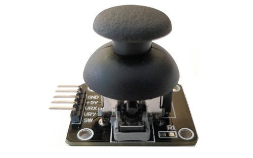
Pin configuration of Joystick module
Joystick module consists of three 5 pins. Description of each pin is given below:
| Pin No. | Pin Name | Description |
| 1 | Gnd | Connect to ground terminal of power supply |
| 2 | +5v | connect 5 volt power supply to this pin |
| 3 | VRx | It provide voltage w.r.t x axis position of joystick |
| 4 | VRy | It provide voltage w.r.t Y axis position of joystick |
| 5 | SW | Switch at the center |
We can connect joystick module to any microcontroller, like Arduino, avr microcontroller and pic microcontroller. But in this tutorial, we are PIC16F877A microcontroller. So to interface this module with pic microcontroller, we need to use two ADC channels of pic microcontroller and one input port of pic microcontroller. I recommend you to read these article first to know how to use adc module and input port of pic microcontroller:
- How to measure analog voltage with pic microcontroller
- How to use input output ports of pic microcontroller
- LED blinking using pic microcontroller
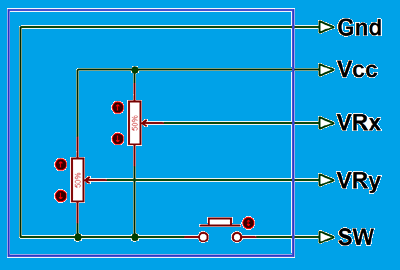
Circuit diagram of joystick module is shown below:
How Joystick module works?
So before interface this module with pic microcontroller, lets see how it works. when we move this module on left on right side value of VRX varies and when we move this module up or down, value of VRY varies and when we move it in diagonal direction values of both VRX and VRY varies. When we press it in the middle position, SW pins becomes high. The values of VRX, VRY and SW changes according to picture shown below. 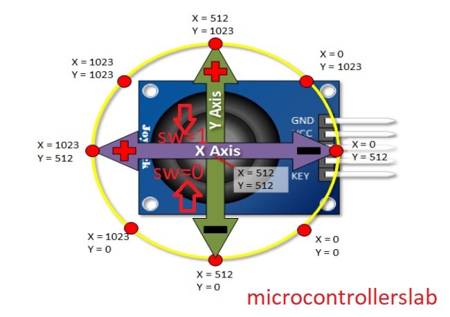
So above picture gives us the clear idea that how joystick module works. Now we can interface it with pic microcontroller very easily by using two analog to digital converter module and one input pin of pic microcontroller. So now lets see how to interface joystick with pic16f877a microcontroller
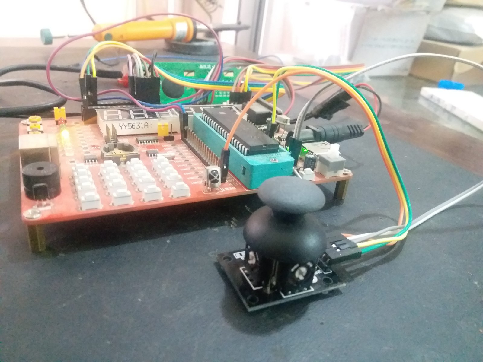
joystick module interfacing with pic microcontroller
Interfacing circuit for joystick module is shown below. For demonstration purpose we are using Five Light emitting diodes which are connected with PORTD of PIC16F877A microcontroller. When we move joystick to the left side, left side LED will glow. When we move joystick to the right side, right position LED will glow and similarly for up and down positions. When we press the joystick in the middle position, middle LED will turn on and turn off as soon as we release the button.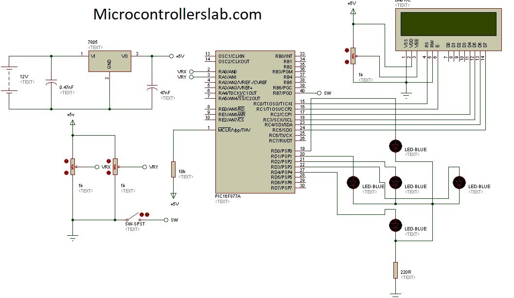
Circuit diagram given above is design used proteus. Proteus do not have built in joystick module, so we are using two variable resistors and one push button for demonstration. VRx and VRy is connected two analog channel zero and analog channel one of pic16f877a microcontroller and SW pin is connected with RB7 pin which will be configured as a digital input pin in code of pic microcontroller.
code of joystick module interfacing with pic microcontroller
Code for this project is written in c language and using Mikro c for pic compiler. Code is uploaded to pic16f877a microcontroller with pic kit 3. Lets start understanding working of the code.
int VRX,VRY, SW;
void main(void)
{
ADC_Init();
TRISD = 0x00; // PORTD is decleared as a output
PORTD= 0x00; // it is initialize as zero
TRISB.B7=1; // PIN NUMBER 1 IS DECLARED AS A INPUT
PORTB.B7=0; // initiaizwd pin to zero
while(1) { // Endless loop

VRX=Adc_read(0);
VRY=Adc_read(1);
if ( VRX < 200)
{
PORTD.B0=1;
PORTD.B1=0;
}
if ( VRX > 800)
{
PORTD.B0=0;
PORTD.B1=1;
}
else
{
PORTD.B0=0;
PORTD.B1=0;
}
if ( VRY < 200)
{
PORTD.B2=1;
PORTD.B3=0;
}
if ( VRY > 800)
{
PORTD.B2=0;
PORTD.B3=1;
}
else
{
PORTD.B2=0;
PORTD.B3=0;
}
if( PORTB.B7==1)
{
PORTD.B4=0;
}
else
{
PORTD.B4=1;
}
}
}
First we initialize the ports of pic microcontroller, PORTD is declared as a output PORT and pin number 7 of PORTB is declared as a input pin. adc_read() function initialize the ADC module of pic microcontroller. After that in while loop, we measured the voltage of VRX and VRY. After measurements has been done, we are using control statements to turn on and turn off light emitting diodes according position of joystick.