Learn to make a web server with MicroPython to control outputs using Raspberry Pi Pico GPIO pins. In this tutorial, we will create a raspberry Pi Pico web server which contains an ON and an OFF button. The ON and OFF button controls the LED connected to one of the GPIO pins of Raspberry Pi Pico.
Recommended Components
The following components are used in this project or are helpful for getting started with Raspberry Pi Pico development.
| Component | How it’s used in this project | Buy on Amazon |
|---|---|---|
| Raspberry Pi Pico | The RP2040 microcontroller board used in this tutorial. | Check Price |
| ESP8266 ESP-01 Module | Wi-Fi module that serves the web page from the Pico. | Check Price |
| LED Assortment Kit | LED toggled on/off from the web server buttons. | Check Price |
| Breadboard | Solderless breadboard for building the circuit. | Check Price |
| Jumper Wires | Male-to-male / male-to-female wires for the connections. | Check Price |
As an Amazon Associate we earn from qualifying purchases. Prices and availability are accurate as of the date/time indicated and are subject to change.
Raspberry Pi Pico does not support Wi-Fi capabilities hence we have to use a separate Wi-Fi module to enable Wi-Fi connectivity. Therefore, we will interface and program ESP-01 Wi-Fi module with Raspberry Pi Pico to enable Wi-Fi features. We will use Thonny IDE to program Raspberry Pi Pico with ESP-01 in MircoPython to control an LED. We will use AT commands through the serial port that is UART to configure the ESP-01 Wi-Fi module.
Prerequisites
Before we start this lesson make sure you are familiar with and have the latest version Python 3 in your system, have set up MicoPython in Raspberry Pi Pico, and have a running Integrated Development Environment(IDE) in which we will be doing the programming. We will be using the same Thonny IDE as we have done previously when we learned how to blink and chase LEDs in micro-python. If you have not followed our previous tutorial, you check here:
If you are using uPyCraft IDE, you can check this getting started guide:
Recommended Reading: Interface ESP8266 WiFi Module with Raspberry Pi Pico
Interfacing Raspberry Pi Pico with an LED and ESP-01
This section shows how to connect Raspberry Pi Pico with an LED and ESP-01.
Parts Required
We will require the following components:
- Raspberry Pi Pico
- LED
- 220 ohm resistor
- ESP-01 Module
- Connecting Wires
- Breadboard
Raspberry Pi Pico with LED
Connect an output pin of Raspberry Pi Pico with the LED’s anode terminal through a 220 ohm current limiting resistor. Also, make sure to connect cathode terminal of an LED with the ground pin of the board.
The connections between the two devices which we are using can be seen below.
| LED | Raspberry Pi Pico |
| Cathode (-) | GND |
| Anode (+) | GP16 |
Raspberry Pi Pico with ESP-01
The ESP-01 module consists of 8 pins. However we will use 5 pins to connect with the Pi Pico board. These include the VCC, EN, GND, RX and TX pins. RX and TX pins of the module will be connected with the UART pins of the Pi Pico board. Let us first have a look at the Raspberry Pi Pi UART Pins.
Raspberry Pi Pico UART Pins
Raspberry Pi Pico contains two identical UART peripherals with separate 32×8 Tx and 32×12 Rx FIFOs.

The following table lists the GPIO pins for both UART peripherals which are exposed on Raspberry Pi Pico development board pinouts.
| UART Pins | GPIO Pins |
| UART0-TX | GP0/GP12/GP16 |
| UART0-RX | GP1/GP13/GP17 |
| UART1-TX | GP4/GP8 |
| UART1-RX | GP5/GP9 |
For this guide we will use UART0-TX and RX pins.
Follow the connection diagram below to connect the two devices.
| Raspberry Pi Pico | ESP-01 |
| 3.3V | VCC |
| 3.3V | EN |
| GND | GND |
| GP1 (UART0 RX) | TX |
| GP0 (UART0 TX) | RX |
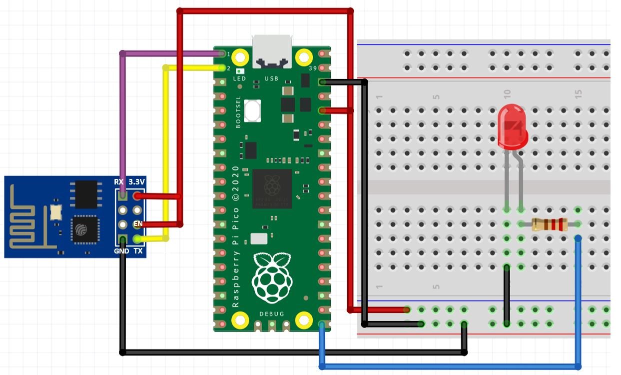
Connection Diagram Raspberry Pi Pico with LED and ESP-01
We have used the same connections as given in the two tables above. All three devices will be commonly grounded.
The diagram below shows the connection diagram of Raspberry Pi Pico with an LED and ESP-01.
MicroPython Script Raspberry Pi Pico Control GPIO Output Web Server
import uos
import machine
import utime
from machine import Pin

recv_buf="" # receive buffer global variable
led_state = "OFF"

print()
print("Machine: \t" + uos.uname()[4])
print("MicroPython: \t" + uos.uname()[3])


led=Pin(16,Pin.OUT)
uart0 = machine.UART(0, baudrate=115200)
print(uart0)

def Rx_ESP_Data():
    recv=bytes()
    while uart0.any()>0:
        recv+=uart0.read(1)
    res=recv.decode('utf-8')
    return res
def Connect_WiFi(cmd, uart=uart0, timeout=3000):
    print("CMD: " + cmd)
    uart.write(cmd)
    utime.sleep(7.0)
    Wait_ESP_Rsp(uart, timeout)
    print()

def Send_AT_Cmd(cmd, uart=uart0, timeout=3000):
    print("CMD: " + cmd)
    uart.write(cmd)
    Wait_ESP_Rsp(uart, timeout)
    print()

def Wait_ESP_Rsp(uart=uart0, timeout=3000):
    prvMills = utime.ticks_ms()
    resp = b""
    while (utime.ticks_ms()-prvMills)<timeout:
        if uart.any():
            resp = b"".join([resp, uart.read(1)])
    print("resp:")
    try:
        print(resp.decode())
    except UnicodeError:
        print(resp)

Send_AT_Cmd('AT\r\n')          #Test AT startup
Send_AT_Cmd('AT+GMR\r\n')      #Check version information
Send_AT_Cmd('AT+CIPSERVER=0\r\n')      #Check version information
Send_AT_Cmd('AT+RST\r\n')      #Check version information
Send_AT_Cmd('AT+RESTORE\r\n')  #Restore Factory Default Settings
Send_AT_Cmd('AT+CWMODE?\r\n')  #Query the Wi-Fi mode
Send_AT_Cmd('AT+CWMODE=1\r\n') #Set the Wi-Fi mode = Station mode
Send_AT_Cmd('AT+CWMODE?\r\n')  #Query the Wi-Fi mode again
Connect_WiFi('AT+CWJAP="A1601","123456789104"\r\n', timeout=5000) #Connect to AP
Send_AT_Cmd('AT+CIFSR\r\n',timeout=5000)    #Obtain the Local IP Address
Send_AT_Cmd('AT+CIPMUX=1\r\n')    #Obtain the Local IP Address
utime.sleep(1.0)
Send_AT_Cmd('AT+CIPSERVER=1,80\r\n')    #Obtain the Local IP Address
utime.sleep(1.0)
print ('Starting connection to ESP8266...')
while True:
    res =""
    res=Rx_ESP_Data()
    utime.sleep(2.0)
    if '+IPD' in res: # if the buffer contains IPD(a connection), then respond with HTML handshake
        id_index = res.find('+IPD')
        if '?led_on' in res:
            print('LED ON')
            led_state = "ON"
            led.value(1)            #Set led turn on
        if '?led_off' in res:
            print('LED OFF')
            led.value(0)            #Set led turn on
            led_state = "OFF"
        print("resp:")
        print(res)
        connection_id =  res[id_index+5]
        print("connectionId:" + connection_id)
        print ('! Incoming connection - sending webpage')
        uart0.write('AT+CIPSEND='+connection_id+',1082'+'\r\n')  #Send a HTTP response then a webpage as bytes the 108 is the amount of bytes you are sending, change this if you change the data sent below
        utime.sleep(1.0)
        uart0.write('HTTP/1.1 200 OK'+'\r\n')
        uart0.write('Content-Type: text/html'+'\r\n')
        uart0.write('Connection: close'+'\r\n')
        uart0.write(''+'\r\n')
        uart0.write('<!DOCTYPE HTML>'+'\r\n')
        html ='<html> <head> <meta name=\"viewport\" content=\"width=device-width, initial-scale=1\"> <link rel=\"stylesheet\" href=\"https://use.fontawesome.com/releases/v5.7.2/css/all.css\" integrity=\"sha384-fnmOCqbTlWIlj8LyTjo7mOUStjsKC4pOpQbqyi7RrhN7udi9RwhKkMHpvLbHG9Sr\" crossorigin=\"anonymous\"> <style> html { font-family: Arial; display: inline-block; margin: 0px auto; text-align: center; } .button { background-color: #ce1b0e; border: none; color: white; padding: 16px 40px; text-align: center; text-decoration: none; display: inline-block; font-size: 16px; margin: 4px 2px; cursor: pointer; } .button1 { background-color: #000000; } </style> </head> <body> <h2>Raspberry Pi Pico Web Server</h2> <p>LED state: <strong>' + led_state + '</strong></p> <p> <i class=\"fas fa-lightbulb fa-3x\" style=\"color:#c81919;\"></i> <a href=\\\"?led_on\\\"><button class=\"button\">LED ON</button></a> </p> <p> <i class=\"far fa-lightbulb fa-3x\" style=\"color:#000000;\"></i> <a href=\\\"?led_off\\\"><button class=\"button button1\">LED OFF</button></a> </p> </body> </html>'
        uart0.write(html +'\r\n')
        utime.sleep(6.0)
        Send_AT_Cmd('AT+CIPCLOSE='+ connection_id+'\r\n') # once file sent, close connection
        utime.sleep(6.0)
        res="" #reset buffer
        print ('Waiting For connection...')
How the Code Works?
We will start by importing the uos and machine module. We also import the utime module so that we will be able to add a delay of 10 seconds in between our readings. Moreover, we import Pin class from the machine module as we have to deal with the GPIO pin connected with the LED.
import uos
import machine
import utime
from machine import Pin
Then, we will print the information about our current operating system in the Thonny shell terminal. We will uos.uname() and print the operating system version and release.
print()
print("Machine: \t" + uos.uname()[4])
print("MicroPython: \t" + uos.uname()[3])
Next we will create a variable which holds the state of LED. We are also displaying the current state of LED on the web page. Hence, we will save the state of the LED in the led_state variable. Initially, we set the led_state value to OFF.
led_state = "OFF"In this line, we create an instance of the Pin object “led”.
led=Pin(16,Pin.OUT) The Pin() class takes three parameters as shown below:
Pin(Pin_number, pin_mode, pull, value)- First argument is a pin number to which we want to configure in different modes such as input, output, etc.
- Second argument defines the pin mode such as digital input (Pin.IN), digital output (Pin.OUT), open-drain (OPEN_DRAIN).
- Third argument specifies if we want to enable pull-up and pull-down internal resistor of a GPIO pin. These pull-up and pull-down resistors become handy when we want to use GPIO pins as a digital input pin (PULL_UP, or PULL_DOWN).
- Last argument defines the initial state of GPIO pin as either active high (1) or active low (0). But, by default, the GPIO initial state on reset is 0 (active low).
Initialize UART Communication
Then we will create an uart object by using UART() and specify the UART channel as the first parameter and the baud rate as the second parameter. We are using UART0 in this case with baud rate 115200 for the uart communication. ESP8266 has a default baud rate of 115200 hence we will use the same baud rate here for Raspberry Pi Pico UART communication in order to create synchronization. Moreover we will also print the UART details in the shell terminal.
uart0 = machine.UART(0, baudrate=115200)
print(uart0)
This Connect_WiFi() function is used to connect ESP8266 with WiFi.
def Connect_WiFi(cmd, uart=uart0, timeout=3000):
    print("CMD: " + cmd)
    uart.write(cmd)
    utime.sleep(7.0)
    Wait_ESP_Rsp(uart, timeout)
    print()
Next, we will define three functions. The first one is Rx_ESP_Data(). This reads the serial data being received. This data is decoded from UTF-8 format and returned.
def Rx_ESP_Data():
    recv=bytes()
    while uart0.any()>0:
        recv+=uart0.read(1)
    res=recv.decode('utf-8')
    return res
The second function is Send_AT_Cmd(cmd, uart=uart0, timeout=3000). It takes in three parameters, the AT command, the UART channel and the response time. This function will be used to it send an AT command to ESP8266 via uart0. The response time is set to 3 seconds.
def Send_AT_Cmd(cmd, uart=uart0, timeout=3000):
    print("CMD: " + cmd)
    uart.write(cmd)
    Wait_ESP_Rsp(uart, timeout)
    print()
The Wait_ESP_Rsp(uart=uart0, timeout=3000) function waits for 3 seconds to get the response from ESP8266. After receiving the data from ESP8266 it concatenates the received bytes and prints them on the shell terminal.
def Wait_ESP_Rsp(uart=uart0, timeout=3000):
    prvMills = utime.ticks_ms()
    resp = b""
    while (utime.ticks_ms()-prvMills)<timeout:
        if uart.any():
            resp = b"".join([resp, uart.read(1)])
    print("resp:")
    try:
        print(resp.decode())
    except UnicodeError:
        print(resp)
AT Commands
Now let us look at the series of AT commands that we will send through UART0 to ESP8266.
Send_AT_Cmd('AT\r\n')          #Test AT startup
Send_AT_Cmd('AT+GMR\r\n')      #Check version information
Send_AT_Cmd('AT+CIPSERVER=0\r\n')      #Check version information
Send_AT_Cmd('AT+RST\r\n')      #Check version information
Send_AT_Cmd('AT+RESTORE\r\n')  #Restore Factory Default Settings
Send_AT_Cmd('AT+CWMODE?\r\n')  #Query the Wi-Fi mode
Send_AT_Cmd('AT+CWMODE=1\r\n') #Set the Wi-Fi mode = Station mode
Send_AT_Cmd('AT+CWMODE?\r\n')  #Query the Wi-Fi mode again
Connect_WiFi('AT+CWJAP="YOUR_SSID","YOUR_PASSWORD"\r\n', timeout=5000) #Connect to AP
Send_AT_Cmd('AT+CIFSR\r\n',timeout=5000)    #Obtain the Local IP Address
Send_AT_Cmd('AT+CIPMUX=1\r\n')    #Obtain the Local IP Address
utime.sleep(1.0)
Send_AT_Cmd('AT+CIPSERVER=1,80\r\n')    #Obtain the Local IP Address
utime.sleep(1.0)AT: This type of command is used to test the startup function of WiFi module. The response would be ok, against this command if everything is ok.
Send_AT_Cmd('AT\r\n') #Test AT startupAT+GMR : This type of AT command is used to check the version of AT command and we used SDK version of AT command in this type of WIFI module.
Send_AT_Cmd('AT+GMR\r\n') #Check version informationAT+CIPSERVER=0: This configures the ESP8266 as server and sets the mode as 0 which means delete server (need to follow by restart)
Send_AT_Cmd('AT+CIPSERVER=0\r\n') AT+RST: This type of command is used for reset the WiFi module when it is in working condition. The response would be ok, when reset the module.
Send_AT_Cmd('AT+RST\r\n') AT+RESTORE: This type of command is used to restore factory settings means, when this command is entered then all the parameters are reset automatically to default one’s.
Send_AT_Cmd('AT+RESTORE\r\n') #Restore Factory Default SettingsAT+CWMODE? : This type of command is used to query the WiFi mode of ESP8266.
Send_AT_Cmd('AT+CWMODE?\r\n') #Query the WiFi modeAT+CWMODE=1 : This sets the WiFi mode of ESP8266 in this case in station mode.
Send_AT_Cmd('AT+CWMODE=1\r\n') #Set the WiFi mode = Station modeAT+CWJAP=”SSID”,”PASSWORD”\r\n’, timeout=TIME_ms : This connects the ESP8266 with an AP whose SSID and password are given, The timeout here is the reconnection time.
Connect_WiFi('AT+CWJAP="YOUR_SSID","YOUR_PASSWORD"\r\n', timeout=5000) #Connect to APAT+CIFSR: This command obtains the local IP address.
Send_AT_Cmd('AT+CIFSR\r\n')AT+CIPMUX=1:This command is used to enable multiple connections (maximum 4)
Send_AT_Cmd('AT+CIPMUX=1\r\n')AT+CIPSERVER=1: This command configures ESP8266 as server.
Send_AT_Cmd('AT+CIPSERVER=1,80\r\n')while loop
Inside the while loop, we will first call Rx_ESP_Data() which returns the data that the ESP8266 receives. This is saved in the variable ‘res.’
Add a delay of 2 seconds before proceeding further.
res =""
res=Rx_ESP_Data()
utime.sleep(2.0)
Next, we will check if the buffer contains an IPD connection or not. If it does then, respond with an HTML handshake.
We will check if the request contains ‘?led_on’ or ‘?led_off’ strings. If we receive ?led_on in request then we will turn on the LED and also update the status of the LED indication variable (led_state) to ON. Likewise, if we receive ?led_off in request then we will turn off the LED and also update the status of the LED indication variable (led_state) to OFF.
The response will also be printed in the shell terminal. Additionally, we obtain the connection ID and print it as well.
if '+IPD' in res: # if the buffer contains IPD(a connection), then respond with HTML handshake
        id_index = res.find('+IPD')
        if '?led_on' in res:
            print('LED ON')
            led_state = "ON"
            led.value(1)            #Set led turn on
        if '?led_off' in res:
            print('LED OFF')
            led.value(0)            #Set led turn on
            led_state = "OFF"
        print("resp:")
        print(res)
        connection_id =  res[id_index+5]
        print("connectionId:" + connection_id)
Then by using the uart object on the write() method, we will send the bytes to the UART. First, we are writing the AT command: AT+CIPSEND=’ID’, ‘LENGTH’ This will set the length of the data that will be sent. Next after a delay of 1 second, we will write the HTML script that will build the web page to the serial port. After that, we will close the multiple connections as we are sending the AT command: AT+CIPCLOSE=’ID’. Then we will reset the buffer and wait for the connection.
print ('! Incoming connection - sending webpage')
        uart0.write('AT+CIPSEND='+connection_id+',1082'+'\r\n')  #Send a HTTP response then a webpage as bytes the 108 is the amount of bytes you are sending, change this if you change the data sent below
        utime.sleep(1.0)
        uart0.write('HTTP/1.1 200 OK'+'\r\n')
        uart0.write('Content-Type: text/html'+'\r\n')
        uart0.write('Connection: close'+'\r\n')
        uart0.write(''+'\r\n')
        uart0.write('<!DOCTYPE HTML>'+'\r\n')
        html ='<html> <head> <meta name=\"viewport\" content=\"width=device-width, initial-scale=1\"> <link rel=\"stylesheet\" href=\"https://use.fontawesome.com/releases/v5.7.2/css/all.css\" integrity=\"sha384-fnmOCqbTlWIlj8LyTjo7mOUStjsKC4pOpQbqyi7RrhN7udi9RwhKkMHpvLbHG9Sr\" crossorigin=\"anonymous\"> <style> html { font-family: Arial; display: inline-block; margin: 0px auto; text-align: center; } .button { background-color: #ce1b0e; border: none; color: white; padding: 16px 40px; text-align: center; text-decoration: none; display: inline-block; font-size: 16px; margin: 4px 2px; cursor: pointer; } .button1 { background-color: #000000; } </style> </head> <body> <h2>Raspberry Pi Pico Web Server</h2> <p>LED state: <strong>' + led_state + '</strong></p> <p> <i class=\"fas fa-lightbulb fa-3x\" style=\"color:#c81919;\"></i> <a href=\\\"?led_on\\\"><button class=\"button\">LED ON</button></a> </p> <p> <i class=\"far fa-lightbulb fa-3x\" style=\"color:#000000;\"></i> <a href=\\\"?led_off\\\"><button class=\"button button1\">LED OFF</button></a> </p> </body> </html>'
        uart0.write(html +'\r\n')
        utime.sleep(6.0)
        Send_AT_Cmd('AT+CIPCLOSE='+ connection_id+'\r\n') # once file sent, close connection
        utime.sleep(6.0)
        res="" #reset buffer
        print ('Waiting For connection...')
Create Web page (HTML+CSS)
To build the web page, we will add HTML code and for styling we will add CSS script.
Now let’s go through each line of HTML code to understand how it builds the web page.
In this HTML document, we use buttons, paragraphs, headings, icons and title tags to create a web page. This web page displays two buttons to control the LED connected with Raspberry Pi Pico.
HTML is a hypertext markup language which is used to build web pages. All web browsers understand this language and can read web pages which are based on HTML language.
In HTML, we place all the content of a web page between <html> and </html> tags. The <html> tag shows the beginning of a web page and the </html> indicates the end of a web page.
HTML code mainly includes two parts such as head and body. The head part contains CSS, scripts, meta tags, links of external resources and styling codes. It is placed between <head> and </head> tags.
'<html> <head> <meta name=\"viewport\" content=\"width=device-width, initial-scale=1\"> <link rel=\"stylesheet\" href=\"https://use.fontawesome.com/releases/v5.7.2/css/all.css\" integrity=\"sha384-fnmOCqbTlWIlj8LyTjo7mOUStjsKC4pOpQbqyi7RrhN7udi9RwhKkMHpvLbHG9Sr\" crossorigin=\"anonymous\"> <style> html { font-family: Arial; display: inline-block; margin: 0px auto; text-align: center; } .button { background-color: #ce1b0e; border: none; color: white; padding: 16px 40px; text-align: center; text-decoration: none; display: inline-block; font-size: 16px; margin: 4px 2px; cursor: pointer; } .button1 { background-color: #000000; } </style> </head>HTML
Inside head tags, create a tag to make the web page responsive in any web browser.
<meta name=\"viewport\" content=\"width=device-width, initial-scale=1\">In our web page, we also use icons of lamps to show ON and OFF states.This link tag loads the icons used in the webpage from fontawesome.
<link rel=\"stylesheet\" href=\"https://use.fontawesome.com/releases/v5.7.2/css/all.css\" integrity=\"sha384-fnmOCqbTlWIlj8LyTjo7mOUStjsKC4pOpQbqyi7RrhN7udi9RwhKkMHpvLbHG9Sr\" crossorigin=\"anonymous\">Styling Web Page with CSS
CSS is used to give styles to a web page. To add CSS files in head tags, we use <style></style> tags. This CSS code styles the buttons and web page by specifying the colours, font, font size etc.
This CSS code sets the display text and font type to Arial without margin. It also aligns the content of the web page to the centre. In this MicroPython web server example, we use two buttons to control outputs of Raspberry Pi Pico. HTML supports default buttons. To give styles to these default buttons, we can use CSS. This code performs basic styling of buttons. The .button sets the color of the ON button to red and .button1 sets the color of the OFF button to black.
<style> html { font-family: Arial; display: inline-block; margin: 0px auto; text-align: center; } .button { background-color: #ce1b0e; border: none; color: white; padding: 16px 40px; text-align: center; text-decoration: none; display: inline-block; font-size: 16px; margin: 4px 2px; cursor: pointer; } .button1 { background-color: #000000; } </style>HTML Web Page Body
The second most important part of an HTML document is the body which goes inside the tags <body> and </body>. The body part includes the main content of the web page such as headings, images, buttons, icons, tables, charts, etc. For example, in this Raspberry Pi Pico Control Outputs MicroPython based web server, the body part includes heading, icons and two buttons to control the LED.
<body> <h2>Raspberry Pi Pico Web Server</h2> <p>LED state: <strong>' + led_state + '</strong></p> <p> <i class=\"fas fa-lightbulb fa-3x\" style=\"color:#c81919;\"></i> <a href=\\\"?led_on\\\"><button class=\"button\">LED ON</button></a> </p> <p> <i class=\"far fa-lightbulb fa-3x\" style=\"color:#000000;\"></i> <a href=\\\"?led_off\\\"><button class=\"button button1\">LED OFF</button></a> </p> </body> </html>'We will include the heading of our webpage inside the <h2></h2> tags and it will be “Raspberry Pi Pico Web Server”.
<h2>Raspberry Pi Pico Web Server</h2>Next, there are three HTML paragraphs in our web page. The <p> and </p> tags are used to insert paragraphs in the HTML body.
<p>LED state: <strong>' + led_state + '</strong></p> <p> <i class=\"fas fa-lightbulb fa-3x\" style=\"color:#c81919;\"></i> <a href=\\\"?led_on\\\"><button class=\"button\">LED ON</button></a> </p> <p> <i class=\"far fa-lightbulb fa-3x\" style=\"color:#000000;\"></i> <a href=\\\"?led_off\\\"><button class=\"button button1\">LED OFF</button></a> </p>Indicate LED Status
First paragraph indicates the status of LED. Here, we used the variable “led_state”. As the state of the LED state changes so does the value of led_state variable. Moreover, “+” sign is used to concatenate the led status variable with other text of the paragraph. The <strong> and </strong> tags make the text bold.
<p>LED state: <strong>' + led_state + '</strong></p> Display Icons and Buttons
The second paragraph displays the lamp icon and LED ON button. We use the icons from Font Awesome Icons website. Besides this when a user clicks the LED ON button, you will be redirected to ?led_on URL.
To Create font, we will use the fontawesome.com website. Go to this link (fontawesome) and type light in the search bar as shown below:
You will see many icons for light bulbs. You can select any one of them to be used in your MicroPython web server. We use the first and second lamp icons in this tutorial. After that click on the selected icon.
You will see this window which contains the link tag. Copy this link tag and use it on your HTML page as follows:
<p> <i class=\"fas fa-lightbulb fa-3x\" style=\"color:#c81919;\"></i> <a href=\\\"?led_on\\\"><button class=\"button\">LED ON</button></a> </p>Similarly, in the third paragraph of a web page, we display the lamp icon and LED off button. when a user clicks the LED OFF button, you will be redirected to ?led_off URL.
<p> <i class=\"far fa-lightbulb fa-3x\" style=\"color:#000000;\"></i> <a href=\\\"?led_off\\\"><button class=\"button button1\">LED OFF</button></a> </p>Demonstration
After you have copied the following code onto a new file, click the ‘Save’ icon to save your program code on your PC.
After you have saved the code press the Run button to upload the code to your board. Before uploading code make sure the correct board is selected.
In the shell terminal of your IDE, you will be able to view the IP address after a successful connection gets established:
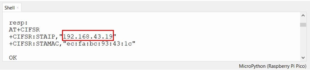
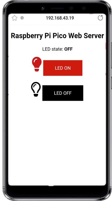
Now, open your web browser either on your laptop or mobile and type the IP address which we have found in the last step. The web server will open up.
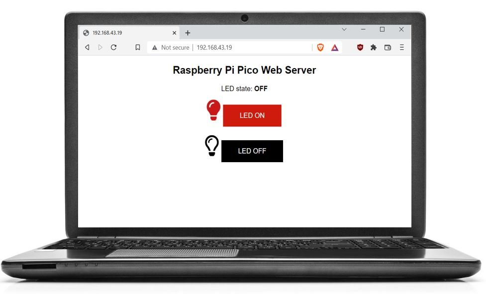
The web page viewed from a cell phone will look like this:
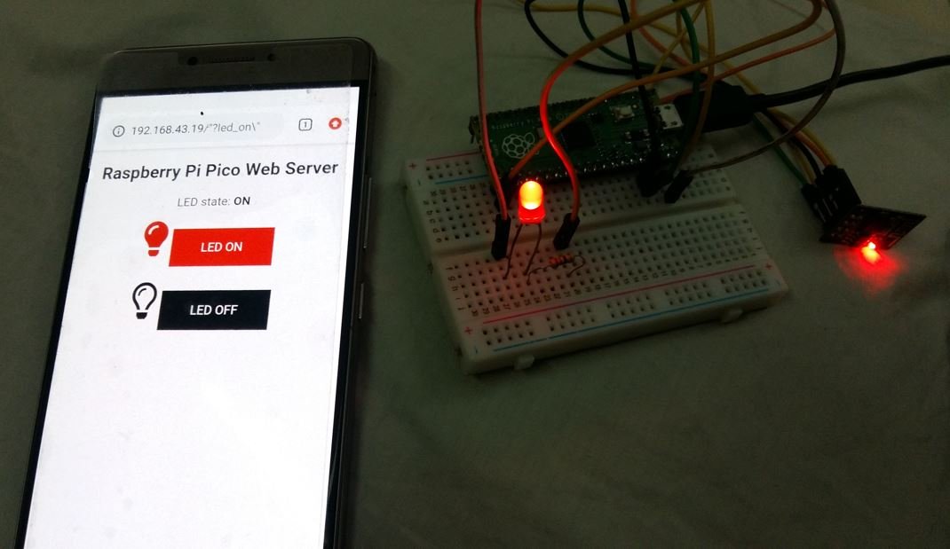
When a user clicks the ON button, they will be redirected to an IP address followed by /?led_on\, and the LED connected with the Raspberry Pi Pico GPIO will turn on. Furthermore, the GPIO state will also update to ON state as shown below:
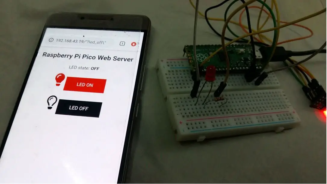
Similarly, when a user clicks the OFF button, they will be redirected to an IP address followed by /?led_off\, and the LED connected with the Raspberry Pi Pico GPIO will turn off. Furthermore, the GPIO state will also update to OFF state as shown below:
Video Demo:
You may also like to read other Web Server projects with Raspberry Pi Pico:
- Raspberry Pi Pico Web Server with BME280 (Weather Station)
- Interface ESP8266 WiFi Module with Raspberry Pi Pico
- Raspberry Pi Pico DHT22 Web Server (Weather Station)
- Raspberry Pi Pico DS18B20 Web Server (Weather Station)
- Raspberry Pi Pico BME680 Web Server with MicroPython
More MicroPython tutorials:
How can this be improved, because it is running very slow and you can not run at the same time other code? Is this limitation due to the esp module? Why I’m asking is because I have an aquarium controller on an Atmega platform and I want to include the wifi part, but I’m not sure that will work if I need to wait so much after the ESP module