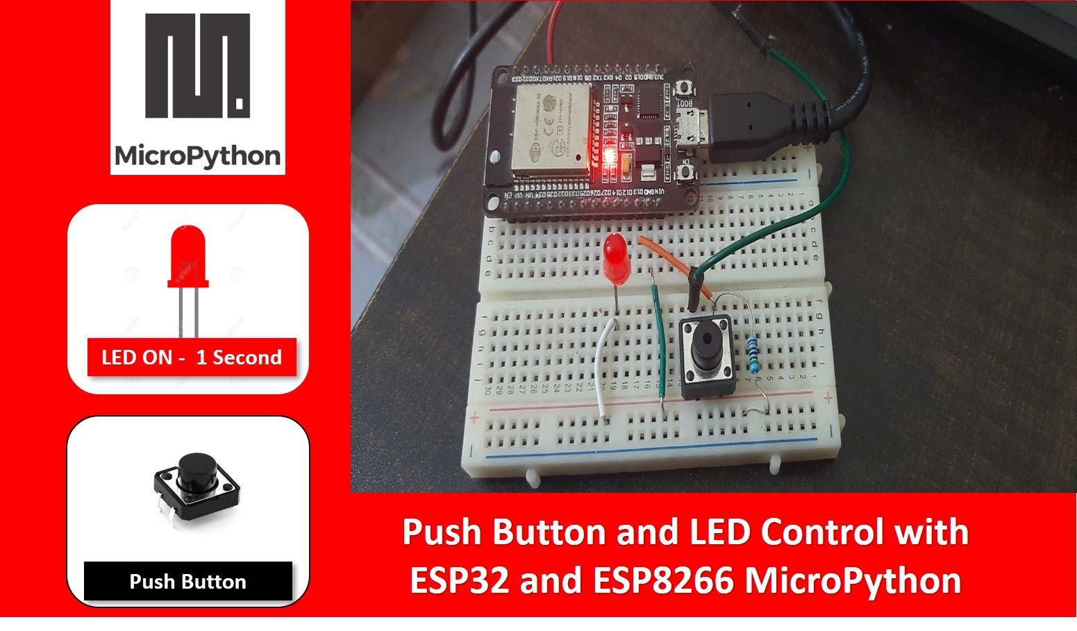
In this tutorial, we will learn how to use a push button in order to turn a led on and off. Previously we learned how to use GPIO pins for the ESP modules as output pins but in this tutorial, we’ll see how the same GPIO pins can also be used to acquire the digital inputs from the modules. Accordingly, we will also show how to interface the Led with our ESP32/ ESP8266 boards. We will be reading the value from the Push Button and lighting up the Led consequently.
Recommended Components
The following components are used in this project or are helpful for getting started with MicroPython on ESP32 and ESP8266.
| Component | How it’s used in this project | Buy on Amazon |
|---|---|---|
| ESP32 Development Board (DevKit V1) | The ESP32 board flashed with MicroPython firmware. | Check Price |
| ESP8266 NodeMCU (ESP-12E) | The ESP8266 NodeMCU running the same MicroPython code. | Check Price |
| Micro USB Cable | Programs and powers the board from your PC. | Check Price |
| Tactile Push Button | Provides the digital input that toggles the LED. | Check Price |
| 5mm LED | Output that turns on and off with the button. | Check Price |
| Resistor Kit (220Ω) | Current-limiting resistor and pull-down for the button. | Check Price |
| Breadboard | Holds the button, LED and resistors for prototyping. | Check Price |
| Jumper Wires | Connect the button and LED to the board. | Check Price |
As an Amazon Associate we earn from qualifying purchases. Prices and availability are accurate as of the date/time indicated and are subject to change.
You may like to check our similar article in which we have learned to control LED with Push button using Arduino IDE:
Push Button Interfacing MicroPython Tutorial Prerequisites
Before we start this lesson make sure you are familiar with and have the latest version of Micro-python firmware installed in your ESP boards and have a running Integrated Development Environment(IDE) in which we will be doing the programming. We will be using the same uPyCraft IDE as we have done previously when we learned how to blink and chase LEDs in micro-python.
- Getting Started with MicroPython on ESP32 and ESP8266
- ESP32 and ESP8266 GPIO Programming with MicroPython – LED Blinking Example
If you are using Thonny IDE, you can check this getting started guide:
Using GPIO Pins of ESP32/ESp8266 as Digital Input/Output
GPIO pins act as both input and output pins with an exception for few. We will be using the GPIO Pins as digital input and as digital output pins in our ESP boards this time when connecting the push button and the LED respectively. One digital pin will be connected to the push button and another one for the LED. We will be taking in the digital input from the push button and acquire the digital output from the LED.
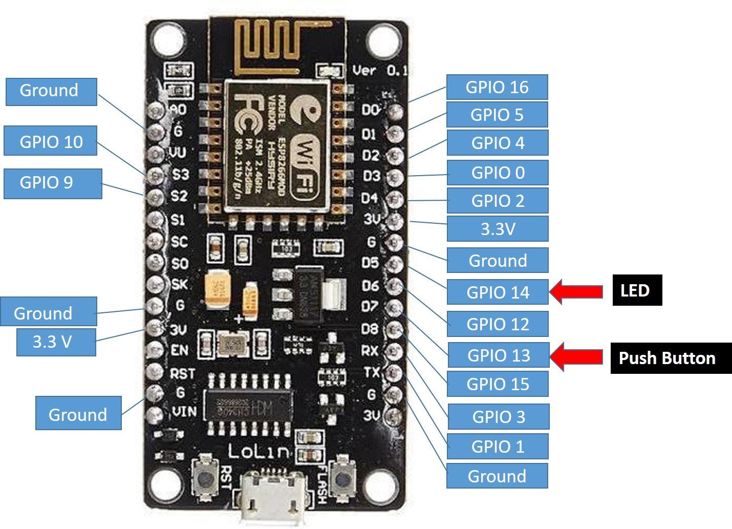
*Note: The GPIO number on ESP 8266 does not match the label which is printed on the board. As an example, D5 corresponds to GPIO 14 and D7 corresponds to GPIO 13. So be careful while coding because in the program code we will use the GPIO number not the number which is imprinted on the board for proper functionality.
Below is the diagram showing the GPIO pins for ESP32 and ESP8266 which we will be using to connect the push button and the LED
ESP8266 GPIO Pinout
For in-depth details on pinout and GPIO pins of ESP8266 NodeMCU Kit, check the following tutorial:
ESP32 GPIO Pinout
As shown in the above diagram we will be using GPIO14 (D5) to connect the LED and GPIO13 (D7) to connect the push button.

As shown in the above diagram we will be using GPIO 14 to connect the LED and GPIO 13 to connect the push button.
You should read the following article to know more about GPIO pins of ESP32.
Push Button Interfacing EP32 and ESP8266 MicroPython
We will read the state of the push button. The push button will give two logical states either high or low. We will connect the push button with the ESP boards using a resistor.
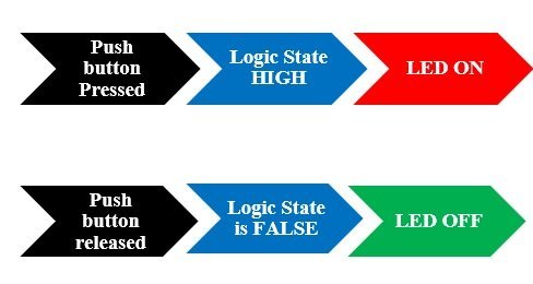
There are two types of resistors that can be used in this project. Pull-up and pull-down resistors. We will be using Pull- down resistors which work on the principle that whenever the push button is pressed, the input to GPIO pin will be logic high state (1) and otherwise logic low state (0). If it is a logic state high that means 1 the LED would switch on and if the logic state is low that means 0 then the LED is off. It works vice-versa if we use pull-up resistors instead.
Connection Diagrams
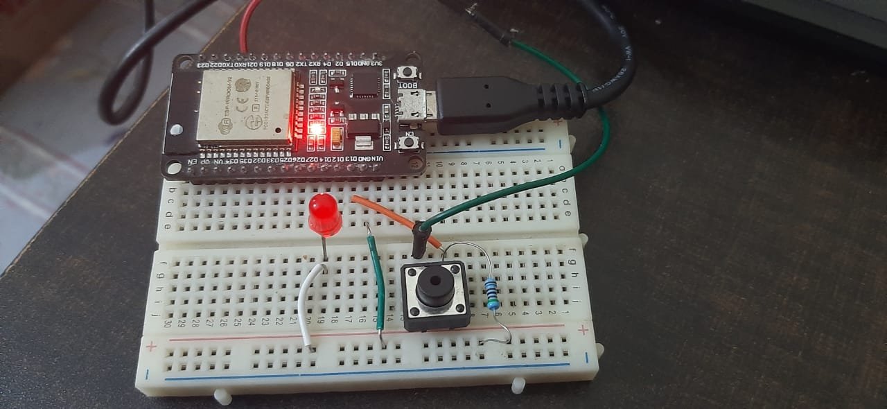
Assembling the Circuit of Push button with ESP8266 and ESP32. Now we will connect the circuit with the LED and push button. The following components are required.
Required Components:
- ESP32/ ESP8266 module
- One LED
- 220 ohm resistor
- 10k ohm resistor
- Breadboard
- Connecting wires
For ESP8266
The below picture shows the schematic for ESP 8266 module with a push button and LED. Assemble your circuit as follows:

For ESP32
Assemble your circuit as follows:
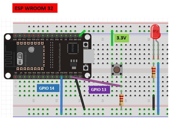
Schematic of ESP32 and ESP8266 with a push button and LED
In the above schematics we can see that GPIO 14 is connected with the anode pin of LED and the cathode pin is connected with the common ground through the 220 ohm resistor.
The push button has four terminals. One terminal is powered by 3.3 volts from ESP8266 and the other terminal is connected by GPIO 13 and the 10k ohm resistor which acts as a pull-down resistor. The other end of the resistor is connected with the common ground.
When the push button is pressed, a logic state of high (1) will be passed on GPIO13 and the push button input will be in high state. When the button is released a logic state of low (0) will be passed on GPIO13 and the push button input will be in a logic state LOW. We will read these two states of the push button and turn on and turn off the LED accordingly.
LED with Button MicroPython Script
We will create a script to control an LED with a push button for ESP32 and ESp8266 in Micropython. Follow the steps in the particular order:
Create a new file by going into the Tools section in UPyCraft IDE and clicking on the ‘New File’ button.

MicroPython Script
The following code reads the state of the push button and lights up the LED accordingly. The code works for both the ESP32 and ESP8266 boards as we have used the same GPIO pins in both the boards. Write the following code in the main.py file in the uPyCraft IDE. Write the following code in that file which is given below.
from machine import Pin
from time import sleep

print('Microcontrollerslab.com')

led = Pin(14, Pin.OUT)    # 22 number in is Output
push_button = Pin(13, Pin.IN)  # 23 number pin is input

while True:

  logic_state = push_button.value()
  if logic_state == True:     # if pressed the push_button
      led.value(1)             # led will turn ON
  else:                       # if push_button not pressed
      led.value(0)             # led will turn OFF
After you have copied the following code onto the file click on ‘Save File’ button to save your program code on your PC. Save your file by giving it a name main.py and save according to your preference by giving the directory.
Flash MicroPython Script to ESP32 and ESP8266
- After you have written the following code in your main.py file go to Tools > Serial and select the serial port. In order to select the Board go to Tools > Board.
- Press the Download and Run button to upload the code to your ESP board.

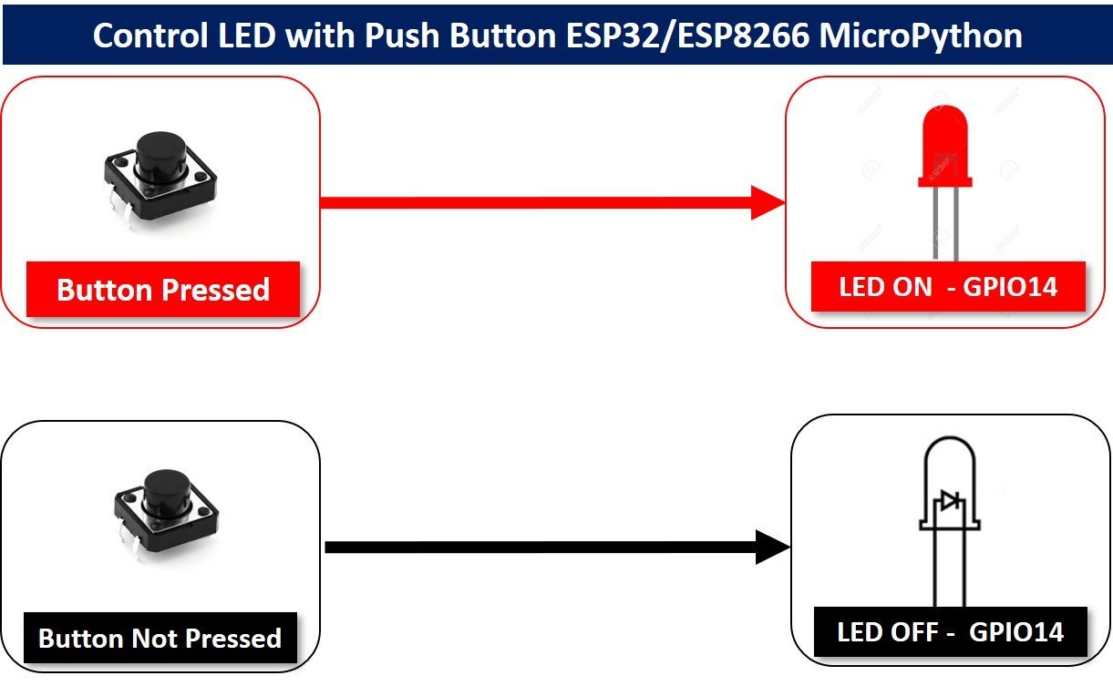
Now if you press the push button LED will glow and if you leave the push button, LED will remain off.
How Code Works?
Firstly, we will import the library for the Pin class from the machine module. To interact with the input/output GPIOs we will import the machine module that contains classes to interact with the GPIOs. We will import the Pin class to interact with the pins.
from machine import Pin MicroPython Define Digital Output
To set a GPIO on or off, we will set it as an output. The first argument in the Pin() class is the pin number on which we are configuring the output. The output is on GPIO14 which is connected to the LED. The second argument shows the pin mode e.g. digital input or digital output mode. As we are configuring pin 14 as the digital output we gave, specifies it as ‘Pin.Out’. This is stored in the object ‘led’.
led = Pin(14, Pin.OUT) MicroPython Define Digital Input
To get the value of a GPIO, we will create a Pin object and set it as an input using ‘Pin.IN’ as the second argument in our Pin() class. The input is on GPIO13 which we specified in the first argument and is connected to the push button. This is stored in the object ‘push_button’.
push_button = Pin(13, Pin.IN) The push button acts as the input and the LED as the output.
We use an infinite loop so we can perform our project endlessly and it does not come to a halt.
while True: #infinite loopRead Push Button State
In order to obtain the value of the input GPIO, we use the function value() on the Pin object without passing any argument inside it. In this case, push_button.value() was used in our program code. The value we would obtain from this is getting stored in the variable logic_state which denotes the logic state of the push button.
logic_state=push_button.value() #storing the value of the push button state in the variable logic_stateIf-Else Statement MicroPython
In this step, we are using an if-else loop. This line states if the push button logic state is TRUE that means 1
if logic_state==True: #if state of button is logic 1To control the output GPIO, we will use the value() function on the Pin object and pass 1 as an argument. This means that the output which is the LED has a logic state HIGH hence it will be ON.
led.value(1) #LED is ONThis means that the output which is the led has a logic state LOW hence the LED will be off.
else:
led.value(0)    #LED is OFF
In this whole if-else loop, if the logic state of the push button is high meaning the push button is pressed, the LED will be ON and if the logic state of the push button is low meaning the push button was released, then the LED will be OFF.
In this tutorial, we learned how to use GPIO pins as both inputs and outputs in the same project by controlling the on/off mechanism of an LED using a push button in Micro-python.
It’s really helpful, keep the good work going!
Very nice!
What if I want to toggle an on/off state, like starting/stopping a motor with the pushbutton?
to toggle state you can use this if condition:
if logic_state==True:
led.value(not led.value())
i
led.value(not push_button.value())
Awesome, man. It helped me to build my first major project and getting an understanding of the subject. A very thorough, detailed and easy explanation.