In this MicroPython PWM tutorial, we will learn how to access the PWM or pulse width modulation modules in ESP32 and ESP8266 using MicroPython firmware. We will look at how to produce the PWM signals with the GPIO pins of the ESP development boards and consequently fade the led as well as control its brightness.
Prerequisites
Before proceeding further with the MicroPython PWM tutorial, you should know how to use MicroPython with ESP32 and ESP8266. You can check these getting started tutorials which we posted previously:
- Getting Started with MicroPython and uPyCraft IDE
- LED Blinking MicroPython ESP32/ESP8266
- Push Button MicroPython ESP32/ESP8266
If you are using Thonny IDE, you can check this getting started guide:
PWM Introduction
PWM means pulse width modulation. It is a type of signal which is obtained from a microcontroller in our case the ESP boards. The output signal is a square waveform which at a particular instance is either high or low. If we are using a 3.3V power supply then the PWM signal would be either high which is 3.3V or low which is 0V. The ‘on time is the duration till which the signal stays high and the ‘off time’ is the duration till which it stays low. In order to better understand the concepts of PWM in our ESP board we need to know about the following two terms which are closely associated with the digital signal:
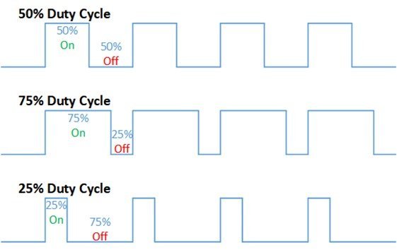
What is Duty Cycle?
Duty cycle is the percentage of time in which the PWM signal is ‘on time’ meaning it remains High. For example if the signal is always OFF it is 0% duty cycle and if it is always ON it is 100% duty signal. The special feature about this is that the user can control the ‘on time’ by controlling the duty cycle. The formula for duty cycle is shown in following expression:
Duty Cycle = ON time of signal / Time period of signal
Frequency
The frequency of a PWM signal is the number of cycles per second and it defines how quickly a PWM signal completes one cycle (Period). That means the Period of a PWM signal is the sum of the ON and OFF time of a PWM signal. For example, if the time period of a signal is 20ms, its frequency will be 50Hz where Hz is the unit of frequency. This formula is used to calculate the frequency:
Frequency = 1/Time Period
Time Period = ON time + OFF time
PWM Pins ESP32 and ESP8266
ESP8266 supports PWM on all the input output pins. On the contrary in ESP32, PWM is supported through all output pins only. The following table gives a brief comparison between the two boards so that we can choose the correct GPIO pins to connect in our circuit.
| ESP32 | ESP8266 | |
|---|---|---|
| Resolution | 16 bit | 10 bit |
| PWM Supported pins | All output pins GPIO0-GPIO5 GPIO12-GPIO33 | Input/output GPIO0-GPIO16 |
How to Initialize PWM in MicroPython
We are going to follow the steps stated below in order to configure PWM in our ESP boards.
- Firstly, we have to choose the PWM channels according to the table specified above.
- Next, we set a particular frequency for our digital signal. 5000Hz is a good value to start off with to work with an LED.
- For best optimization we work in 8-bit resolution hence the duty cycle will vary from 0-255.
- The last step is to attach the output GPIO PIN with a PWM channel that we had chosen before.
MicroPython LED Fading Example using PWM
Now we will learn how to build a simple circuit that fades the LED according to PWM signals. The following components are required to perform this procedure:
Required Components
- ESP32/ESP8266 DEVKIT board
- Breadboard
- One LED
- One 220 ohm resistor
- Connecting Wire
Connection Diagrams
We will connect the LED to GPIO14 on both ESP32 and ESP8266boards. But you can choose another suitable PWM pin accordingly. Make your circuit connections as shown in the diagram below for ESP8266 and ESP32 respectively:
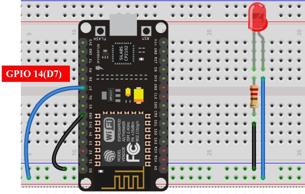
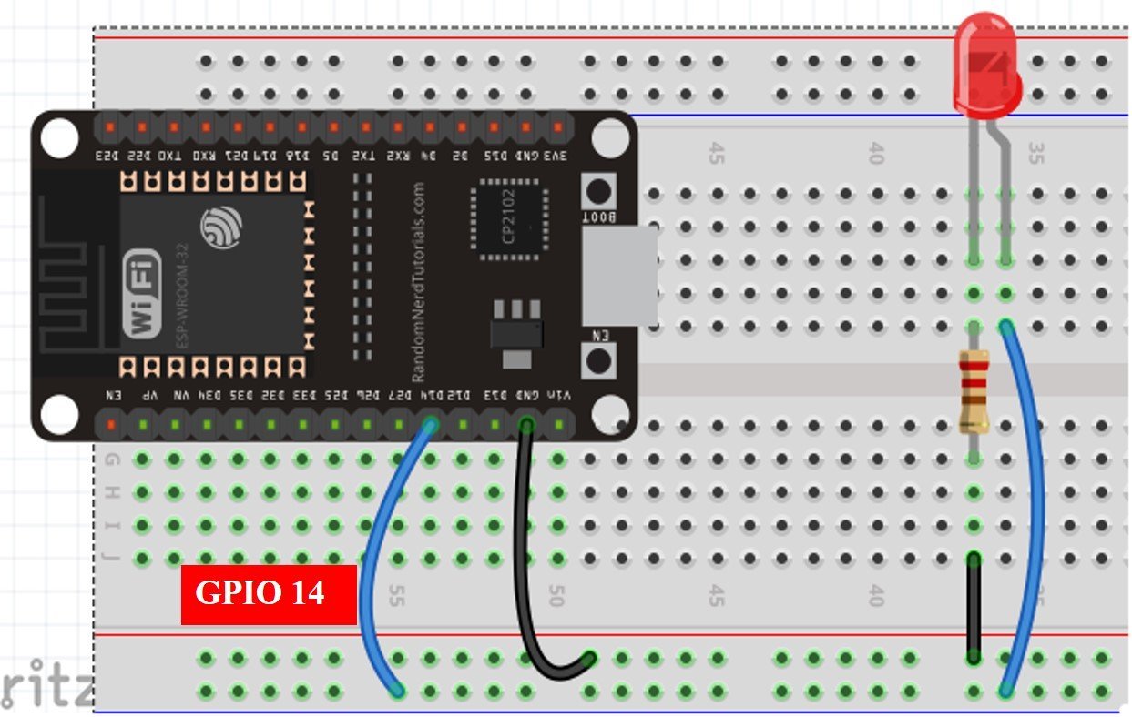
In the above schematics, we can see that GPIO14 is connected with the anode pin of LED, and the cathode pin is connected with the common ground through the 220-ohm resistor.
MicroPython PWM Library
In order to use the PWM module in our ESP boards we have to follow steps:
- Importing the PWM class.
- Secondly, creating a PWM object for the LED. In the PWM object we will pass 3 parameters, the pin it is connected to, the signal frequency and the duty cycle. By default, the duty cycle of output PWM signal is set to 0, if you do not set it while instantiating the PWM object. For example PWM(Pin(14), 5000) shows the PWM is connected on GPIO14 and a frequency of 5000Hz is set.
- The range of frequency can be between 1Hz and 1kHz for ESP8266 and 1Hz to 40MHz for ESP32 with a tradeoff of frequency and duty cycle resolution.
- Currently, MicroPython implementation of PWM for ESP boards supports 10-bit duty cycle resolution for both ESP32 and ESP8266 boards. Therefore, the value of duty cycle can vary between 0 and 1023. That means, if we set the duty of PWM signal to 0% LED will not glow at all and similarly with 100% duty cycle, LED will go with its full brightness capacity.
MicroPython PWM Script
We will fade the LED (low to high) by increasing the duty cycle in our program code. To set a PWM signal, we will define these following parameters in the code:
- Frequency of the signal
- Duty cycle
- PWM channel
- GPIO pin where you want to output the signal
We will create a script for PWM for ESP32 and ESP8266 in MicroPython.
from machine import Pin, PWM
from time import sleep

led = PWM(Pin(14), 5000)

while True:
 for dutyCycle in range(0, 1024):
  led.duty(dutyCycle)
  print(dutyCycle)
  sleep(0.1)
How Code Works?
Now I will explain the steps in which the program code is working.
Importing PWM and Pin Classes
Firstly, in order to interact with the PWM module, we will import the PWM class from the machine module of MicroPython. In order to create a PWM pin to read input/output GPIOs, we will also import the PWM class. We will import the machine module that contains classes to interact with the GPIOs. The sleep module is also imported for use in delays.
from machine import Pin, PWM
from time import sleep
Create PWM Object
Next we create a PWM object called led to pass parameters. The first parameter shows where the pin is connected in our case GPIO14 and the next parameter as the frequency 5000Hz.
led = PWM(Pin(14), 5000)As we did not pass the duty cycle as the third parameter we will incorporate it inside our while loop. It is set as 0% as default. We will use the duty() method on the PWM object to pass our duty cycle as its argument.
led.duty(dutyCycle)Generate Variable Duty Cycle PWM
Inside the infinite loop, we will generate a ‘for’ loop which increases the duty cycle by 1 in each loop after an interval of 5ms. We also use the range() function to initiate the start, stop, and step. The range() function has three parameters and written as follows: range(start, stop, step).
- Start: This shows the starting value for the duty cycle. In our case, we start with 0 duty cycle
- Stop: This shows the stopping value for the duty cycle range except for this value. Because the range of duty cycle for ESP32 and ESP8266 is between 0-1023 and we want to increment the duty cycle by 1 value on each iteration of for loop. Therefore, we will set the stop value to 1024.
- Step: This shows the incrementation value. As we did not pass the third parameter it is set as default which is 1.
for dutyCycle in range (0,1024):
  led.duty(dutyCycle)
  print(dutyCycle)
  sleep(0.005)
During each iteration of for loop, we set the LED’s duty cycle to the current dutyCycle value:
led.duty(dutyCycle)After that, the dutyCycle variable is incremented by 1. Changing the duty cycle is how you produce different levels of brightness.
Demonstration
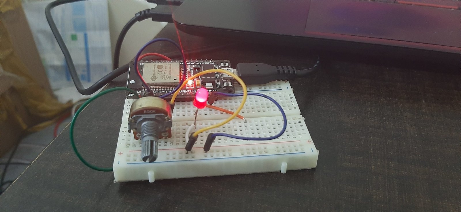
To see the demo of above code, copy this code to UpyCraft or Thonny IDE. Also, attached the LED to GPIO14 of ESP32 or ESP8266. You will see that the brightness of LED increases from low to the highest value as shown in the figure below:

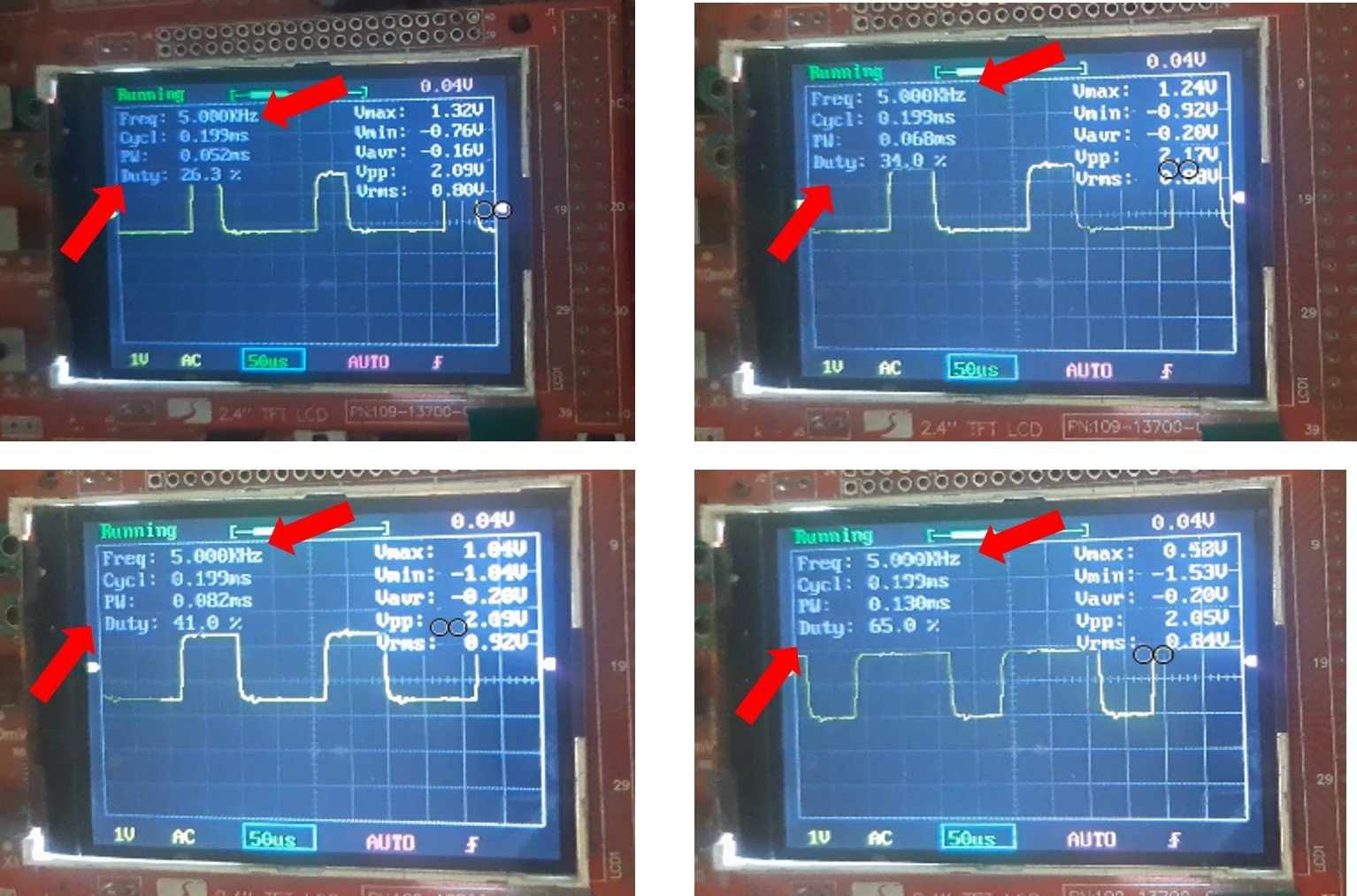
You can also see the output PWM waveform by connecting an oscilloscope to the GPIO14 pin of ESP32 and ESP8266. By doing so, you will see that that the frequency of out signal is 5kHz and duty cycle will also vary from 0% to a maximum value of 100% as follows:
Video Demo
ESP32/ESP8266 Brightness Control using PWM
Now, we will learn how to control the brightness of an LED using the PWM module in ESP32 and ESP8266. In the previous example we achieved this feature by increasing the duty cycle but this time we will change the brightness using a potentiometer. In order to perform this project we need the following equipment:
- ESP32/ESP8266 Development board
- Breadboard
- One LED
- One 220 ohm resistor
- One 10k potentiometer
- Connecting wires
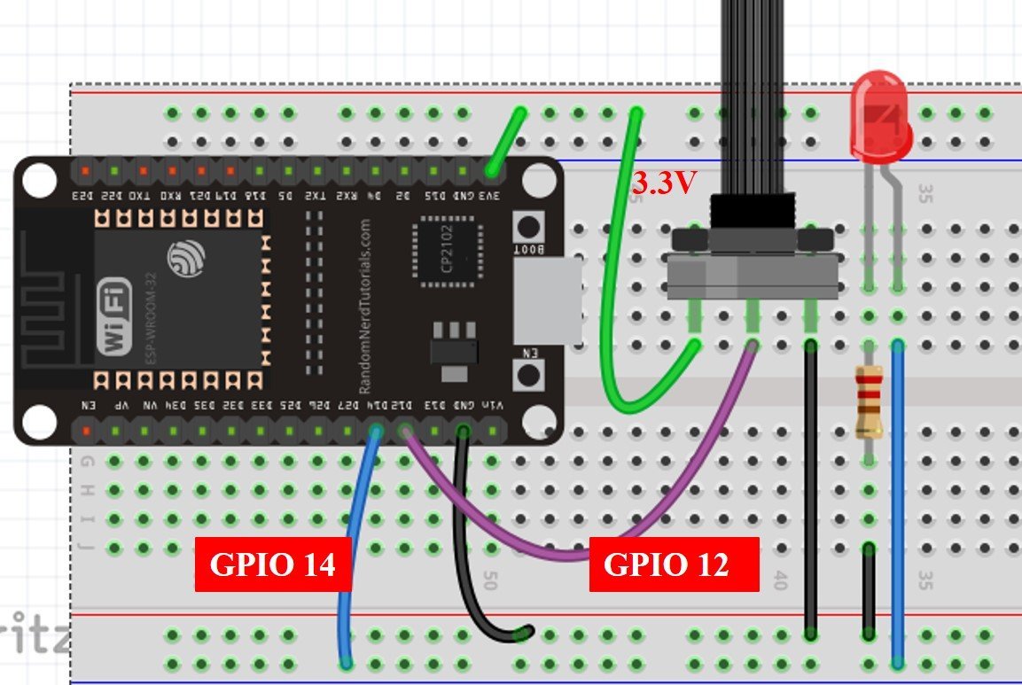
For ESP32 Module, connect the components as shown in the schematic diagram below:
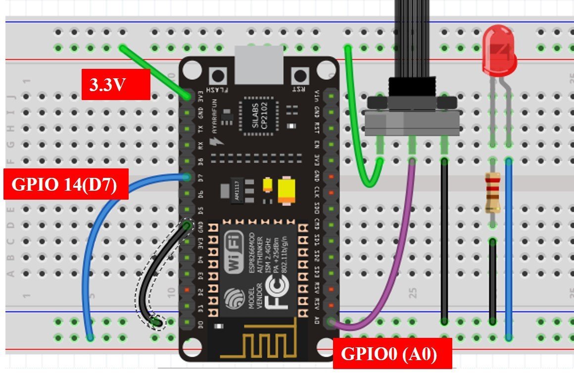
For ESP8266 Module, connect the components as shown in the schematic diagram below:
Brightness Control MicroPython Script
ESP32 Code
from machine import Pin, ADC, PWM          #importing Pin, ADC and PWM classes
from time import sleep                                 #importing sleep class

led=PWM(Pin(14), 5000)             #GPIO14 set as pin and 5000Hz as frequency

potentiometer=ADC(Pin(12))             #creating potentiometer object
potentiometer.width(ADC.WIDTH_12BIT)   #setting ADC resolution to 10 bit
potentiometer.atten(ADC.ATTEN_11DB)         #3.3V full range of voltage

while True:
  potentiometer_value=potentiometer.read()           #reading analog pin
  print(potentiometer_value)
  led.duty(potentiometer_value)             #setting duty cycle value as that of the potentiometer value
  sleep(0.1)
ESP8266 Code
from machine import Pin, ADC, PWM          #importing Pin, ADC and PWM classes
from time import sleep                   #importing sleep class

led=PWM(Pin(14), 5000)
potentiometer=ADC(0)             #creating potentiometer object

while True:
 potentiometer_value=potentiometer.read()           #reading analog pin
 print(potentiometer_value)
 led.duty(potentiometer_value)             #setting duty cycle’s value as that of the potentiometer value
 sleep(0.01)
How the Code works?
Importing Libraries
Firstly we are importing the pin, ADC, and the PWM classes from the machine module and the sleep class from the time module. Next, we are creating a Pin object specifying the GPIO pin and frequency. This is getting stored in the variable ‘led’ which acts as the output. ‘potentiometer’ variable stores the value for the input ADC object connected on pin GPIO12 for ESP32 and pin 0 for ESP8266.
from machine import Pin, ADC, PWM          #importing Pin, ADC and PWM classes
from time import sleep                                 #importing sleep class

led=PWM(Pin(14), 5000)
potentiometer=ADC(0)             #creating potentiometer object
You can read our previously published ADC with MicroPython tutorial here:
Read Analog Signal and Set Duty Cycle
Inside the infinite loop we are reading the analog pin through the method read() from the potentiometer variable and storing it in potentiometer_value. This value will vary from 0-1023 because we have set 10 bit resolution. You will be able to see the values getting printed on the screen. This value is given as a parameter inside the duty() method which is being accessed through the ‘led’ variable.
while True:
 potentiometer_value=potentiometer.read()           #reading analog pin
 print(potentiometer_value)
 led.duty(potentiometer_value) #setting duty cycle’s value as that of the potentiometer value
 sleep(0.01)
Increasing input values from the potentiometer act as increasing duty cycle hence the brightness of the led increases .
In this tutorial, we learned about the PWM module of ESP32 and ESP8266 by fading LED as well as controlling its brightness through a variable resistor using Micro-Python.
You may like to read our other PWM tutorials: