In this tutorial we will learn about the Analog to Digital Converter module and how to read analog values in Esp32 and Esp8266 in MicroPython firmware. We will achieve this by interfacing a potentiometer with our ESP32/ESP8266 boards and read its analog values respectively.
Recommended Components
The following components are used in this project or are helpful for getting started with MicroPython on ESP32 and ESP8266.
| Component | How it’s used in this project | Buy on Amazon |
|---|---|---|
| ESP32 Development Board (DevKit V1) | The ESP32 board flashed with MicroPython firmware. | Check Price |
| ESP8266 NodeMCU (ESP-12E) | The ESP8266 NodeMCU running the same MicroPython code. | Check Price |
| Micro USB Cable | Programs and powers the board from your PC. | Check Price |
| 10kΩ Potentiometer | Supplies the variable analog voltage that is read. | Check Price |
| Breadboard | Holds the potentiometer for prototyping. | Check Price |
| Jumper Wires | Connect the potentiometer to the analog pin. | Check Price |
As an Amazon Associate we earn from qualifying purchases. Prices and availability are accurate as of the date/time indicated and are subject to change.
We have a similar guides for ESP32 and ESP8266 using Arduino IDE:
- ESP8266 NodeMCU ADC using Arduino IDE – Measure Analog Voltage
- ESP32 ADC with Arduino IDE – Measuring voltage example
ADC ESP32 and ESP8266 Prerequisites
Before we start this lesson make sure you are familiar with and have the latest version of MicroPython firmware installed in your ESP boards and have a running Integrated Development Environment(IDE) in which we will be doing the programming. We will be using the same uPyCraft IDE as we have done previously when we learned how to blink and chase LEDs in MicroPython here:
If you are using Thonny IDE, you can check this getting started guide:
ADC ESP32 and ESP8266
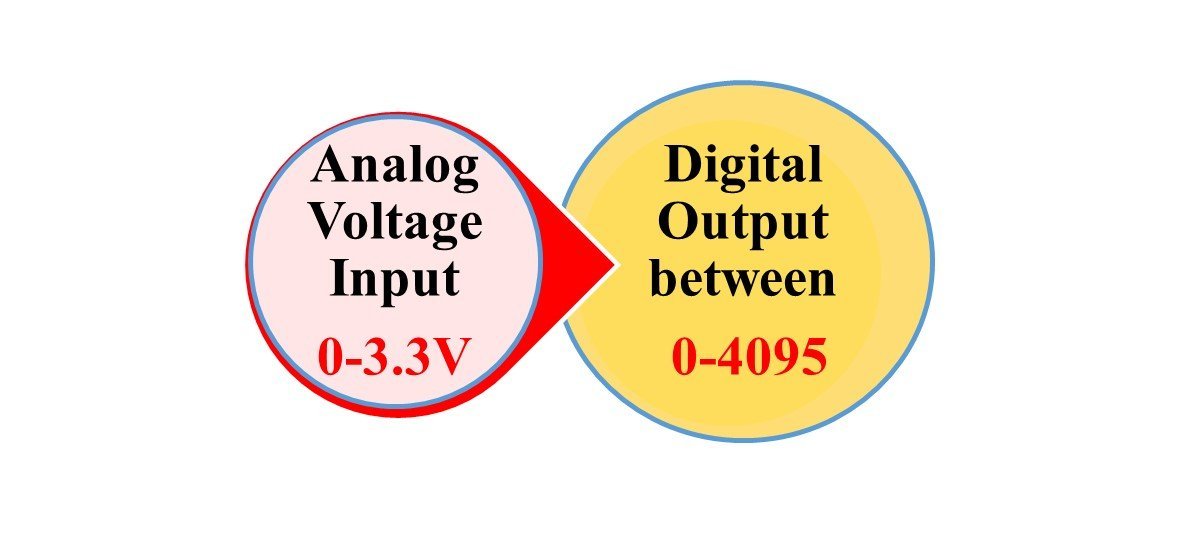
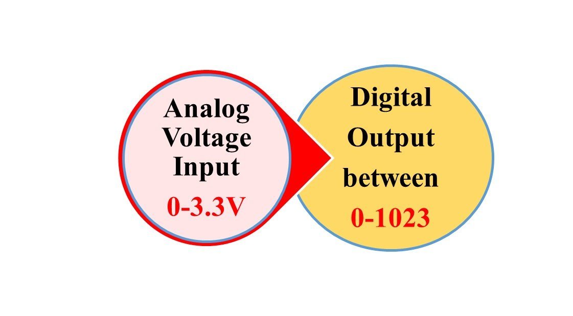
Analog reading works differently for both these ESP boards In ESp32 and Esp8266 analog values are read through varying voltage values between 0-3.3V. The voltage which we obtain is then assigned a value between 0-4095(in the case of sp32) and 0-1023(in the case of esp8266). This means the maximum value 4095 or 1023, in either case, corresponds to a 3.3V and a value of 0 corresponds to 0V. Any in-between corresponding values will also get assigned accordingly.
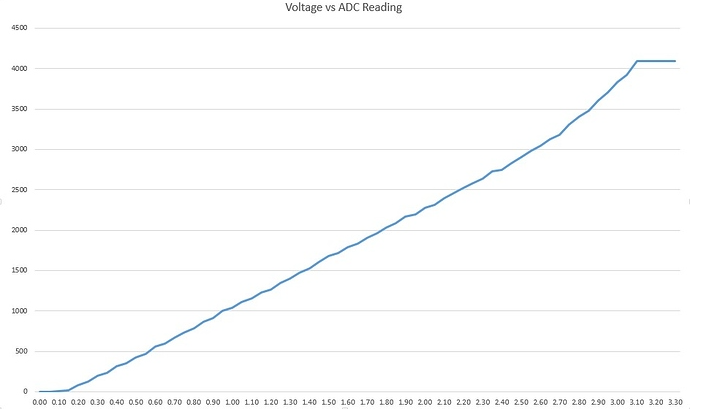
However, there is a slight disadvantage. ADC module is not extremely sensitive to changes in values. It is non-linear in nature. Thus very close values will correspond to similar voltages. For example, 3.3V and 3.2V will both correspond to the value of 4095 or 1023 according to your ESP board. The following graph shows the non-linear relationship between the voltage value and the ADC reading.
ESP32 ADC Channels
ESP32 has a 12-bit resolution which we can change according to our needs. But ESP8266 has a 10-bit resolution that cannot be further manipulated. ESP32 has two 12 bit ADCs(ADC 1 & ADC 2) and supports a maximum of 18 analog channels.
ESP8266 ADC Channels
ESP8266 has a single analog pin namely ADC0 which is usually printed A0 on the board.
The following table shows the comparisons between the two ESP boards in respect to ADC:
| ESP32 | ESP8266 | |
|---|---|---|
| Resolution | 12 bit | 10 bit |
| Voltage | 0-3.3V | 0-3.3V |
| Assigned Value | 0-4095 | 0-1023 |
| Analog Pin | GPIO0, GPIO2, GPIO4, GPIO12, GPIO13, GPIO14, GPIO15,GPIO 25,GPIO 26, GPIO27, GPIO32, GPIO33,GPIO34, GPIO35, GPIO36, and GPIO39 | ADC 0 (A0) |
| Changing Resolution | Can change | Cannot change |
Esp32 vs. Esp8266 Analog Mode
Analog Input Pin out For ESP32 and ESP8266:
For ESP32 board
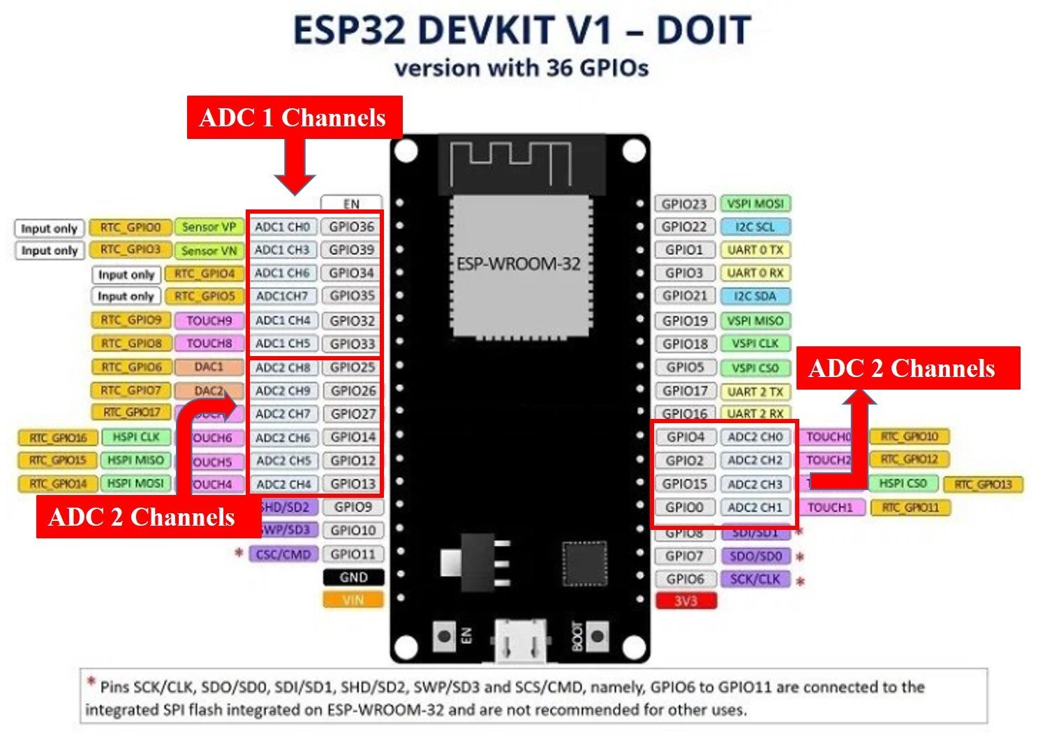
The ESP32 board has 8 channels for ADC1 but the DEVkit only supports 6 of them and for ADC2 it has 10 analog channels:
- ADC1_CH0 :GPIO 36
- ADC1_CH1 :GPIO 37 (NOT AVAILABLE)
- ADC1_CH2 :GPIO 38 (NOT AVAILABLE)
- ADC1_CH3 :GPIO 39
- ADC1_CH4 :GPIO 32
- ADC1_CH5 :GPIO 33
- ADC1_CH6 :GPIO 34
- ADC1_CH7 :GPIO 35
- ADC2_CH0 :GPIO 4
- ADC2_CH1 :GPIO 0
- ADC2_CH2 :GPIO 2
- ADC2_CH3 :GPIO 15
- ADC2_CH4 :GPIO 13
- ADC2_CH5 :GPIO 12
- ADC2_CH6 :GPIO 14
- ADC2_CH7 :GPIO 27
- ADC2_CH8 :GPIO 25
- ADC2_CH9 :GPIO 26
The following diagram shows the analog pins for ESP32 DEVKIT V1.
For ESP8266
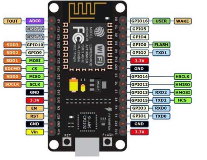
The ESP8266 board has a single analog pin:
- ADC0: A0
The following diagram shows the analog pin for ESP8266.
Reading Analog Inputs with ESP32 and ESP8266 using MicroPython
We will now learn how to read the analog inputs from the ESP boards using a variable resistor i.e. a potentiometer. The following diagram shows the connections of the potentiometer. The center terminal gives the output and the two terminals on the sides are provided VCC and ground respectively.
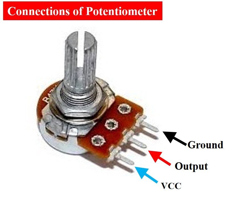
We will connect the potentiometer with any analog channel on our ESP boards whose position we learned previously and then measure its voltage. By turning the upper knob of the potentiometer, variable input voltages would be supplied which would be converted to their corresponding digital values through the ADC module in our ESP boards. The following components are required to perform this procedure:
Required Components:
- ESP32/ESP8266 DEVKIT board
- Breadboard
- Potentiometer
- Connecting Wire
As the ADC module works differently for ESP8266 and ESP32 we will show both the schematics and code separately.
ESP32 and ESP8266 Connection Diagrams
The below picture shows the schematic for the ESP8266 module with a potentiometer. Assemble your circuit as follows:

The below picture shows the schematic for the ESP32 module with a potentiometer. Assemble your circuit as follows:
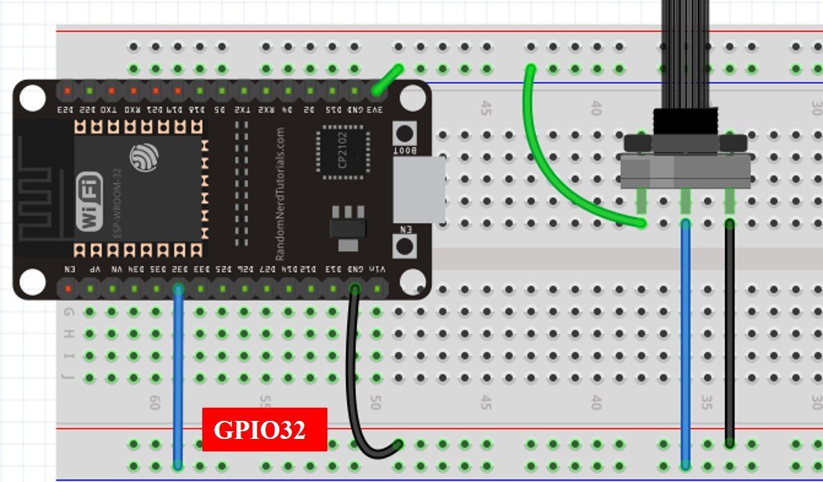
As we can see the one terminal of the potentiometer is powered by 3.3V (green), the center terminal is connected to GPIO pin (blue) and the last one is grounded (black). For ESP8266 the blue wires connect the GPIO0 which is ADC0 and for ESP32 the blue wire connects the GPIO32 which is ADC1_CH4 or ADC1 channel 4.
MicroPython ADC Library
In order to read analog inputs in our ESP boards we have to follow three steps:
- Importing the ADC class.
from machine import ADCSecondly, creating an ADC object for the variable resistor in the form of ADC(Pin(GPIO)), in which GPIO is the number of the GPIO you want to read the analog values from. For the case of ESP32 if we want to connect our input from GPIO32 we will use ADC(Pin(32)) to read its value. In the case of ESP8266, we will use ADC (0) to initiate the ADC object as it only supports the ADC function on the ADC0 pin.
potentiometer = ADC(Pin(32))            #creating potentiometer object
potentiometer = ADC(0)                  #creating potentiometer object
Lastly, in order to read the analog value using the read() method on the ADC object to get the required value.
potentiometer_value = potentiometer.read()ADC MicroPython Script
Followings are the micropython scripts to read analog inputs for ESP32 and ESP8266:
ESP32 MicroPython Code
from machine import Pin, ADC            #importing Pin and ADC class
from time import sleep                  #importing sleep class

potentiometer = ADC(Pin(32))            #creating potentiometer object
potentiometer.atten(ADC.ATTN_11DB)       #3.3V full range of voltage

while True:
 potentiometer_value = potentiometer.read()   #reading analog pin
 print(potentiometer_value)                   #printing the ADC value
 sleep(0.25)
ESP8266 MicroPython Code
from machine import Pin, ADC            #importing Pin and ADC class
from time import sleep                   #importing sleep class

potentiometer = ADC(0)                    #creating potentiometer object

while True:
  potentiometer_value = potentiometer.read()   #reading analog pin
  print(potentiometer_value)                   #printing the ADC value
  sleep(0.25)
How Code Works?
Now I will explain the steps in which the program code is working. Firstly in order to read the analog input, we will import the ADC class. The Pin class is also imported in order to interact with the input/output GPIOs. We will import the machine module that contains classes to interact with the GPIOs. The sleep module is also imported for use in delays.
from machine import Pin, ADC
from time import sleep
Create ADC Object for ESP32
Then we created an ADC object named potentiometer on GPIO 32.
potentiometer = ADC(Pin(32)) Next, we used the atten() method in order to define the resolution. In the atten() method we can pass four arguments which are listed below which define the voltage range.
- ADC.ATTN_0DB : the full range voltage: 0- 1.2V
- ADC.ATTN_2_5DB : the full range voltage: 0- 1.5V
- ADC.ATTN_6DB : the full range voltage: 0- 2.0V
- ADC.ATTN_11DB : the full range voltage: 0-3.3V
potentiometer.atten(ADC.ATTN_11DB)We passed the full range maximum voltage 3.3V argument in our atten() method. This shows that we want to read voltages form 0-3.3V inclusively.
FOR ESP8266
As the ESP8266 has analog support on only a single pin we will create an ADC object named potentiometer on A0 pin.
potentiometer = ADC(0)Reading Digital Value
Next we used an infinite while loop which reads the analog value from the potentiometer endlessly. Using the read() method, we read the value of the potentiometer and store them in the variable ‘potentiometer_value.’
potentiometer_value = potentiometer.read()Lastly we print the potentiometer value and give a delay of 0.25 seconds before another value is printed.
print(potentiometer_value)
sleep(0.25)
Changing ESP32 ADC Resolution
By default, the program will run as a 12 bit ADC giving us values between 0-4095 but we can change the resolution in ESP32 according to our needs. This can be achieved by using the width() method as follows:
ADC.width(bit)In the bit argument we can set our resolution range.The following can act as bit arguments:
- ADC.WIDTH_9BIT: range 0-511
- ADC.WIDTH_10BIT: range 0-1023
- ADC.WIDTH_11BIT: range 0-2047
- ADC.WIDTH_12BIT: range 0-4095
ADC.width(ADC.WIDTH_10BIT) will give us values between 0-1023 when we will rotate the potentiometer.
MicroPython ADC Code Demo
Now let’s see the output of the above-given micropython scripts. Follow these steps to create new project in uPyCraft IDE:
- Build a new file by going into the Tools section in UPyCraft IDE and pressing on the ‘New File’ button.

2. Copy the above given EP32 MicroPython code in that file.
3. Press the ‘Save File’ button to save your program code on your PC. Save your file by giving it a name adc.py and save according to your preference by giving the directory.

4. The next step is to go to Tools > Serial and select the serial port. Also, select the Board to go to Tools > Board.
5. Press the Download and Run button to upload the code to your ESP board.

When you run this code on your ESP boards and rotate the potentiomter knob, you will get the value of ADC after every 0.25 seconds as you can see in the figure below:

ADC output is shown below in shell console:

Analog Voltage Measurement ESP32 and ESP8266 Micropython
In the last section, we have seen how to convert analog signal into digital value using MicroPython with ESP32 and ESP8266. Similarly, we can also convert measured digital value back into voltage by multiplying digital value with the resolution of ADC which is 3.3/4095 and 3.3/1023 for ESP32 and ESP8266, respectively. Now let’s see an example to measure analog voltage signal using MicroPython with ESP32/ESP8266.
Analog Voltage Measurement MicroPython Script
from machine import Pin, ADC            #importing Pin and ADC class
from time import sleep                  #importing sleep class

potentiometer = ADC(Pin(32))            #creating potentiometer object
potentiometer.atten(ADC.ATTN_11DB)       #3.3V full range of voltage

while True:
 potentiometer_value = potentiometer.read() * 3.3 / 4095  #reading analog pin
 print(potentiometer_value)                   #printing the ADC value
 sleep(0.25)
Again, upload this code to ESP32/ESP8266, you will get measured voltage value on shell console instead of digital output value:
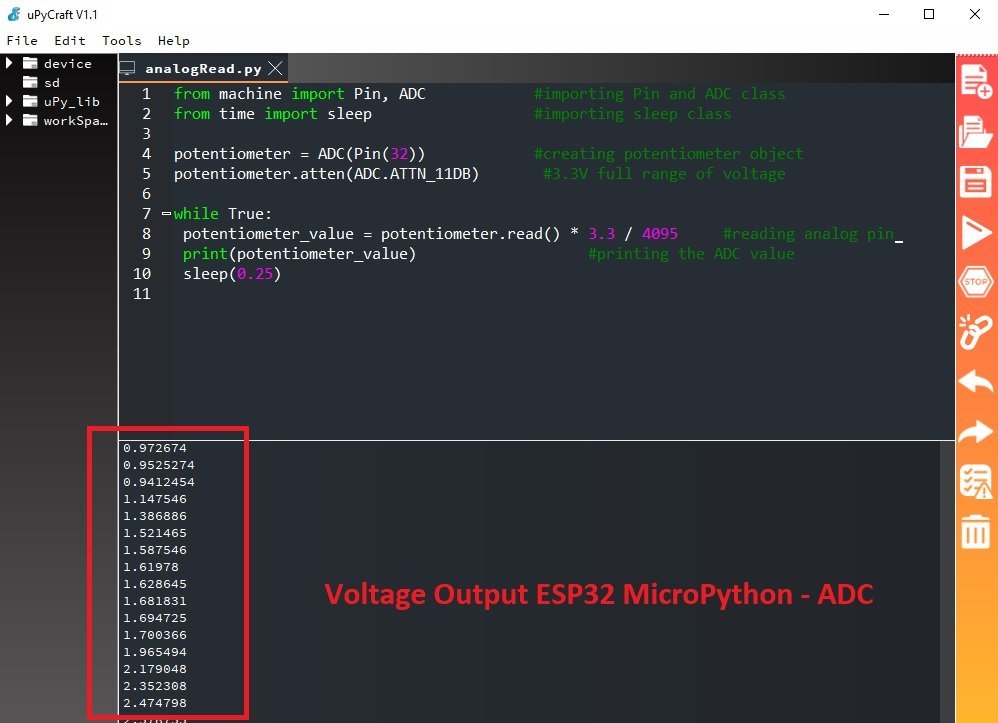
In this line, we multiply the ADC digital value with resolution of ESP32 ADC which is 3.3/4095. It will provide output in the form of voltage.
potentiometer_value = potentiometer.read() * 3.3 / 4095Video Demo
In this tutorial, we learned how to read analog values using MicroPython with ESP32 and ESP8266 boards. You can explore further by looking into these guides: