In this tutorial, we will learn about ADC of ESP8266 NodeMCU using Arduino IDE. Firstly, we will see how to read analog values with ESP8266 ADC. We will achieve this by interfacing a potentiometer with an analog input pin of ESP8266 ADC and read analog voltage across the potentiometer. NodeMCU ADC will convert this analog signal into a digital value and we will display the digital value on Arduino serial monitor.
Similarly, in the second example, we will also convert the measured digital value into analog voltage and display it on the SSD1306 OLED display.
Pre-requisites
We will use Arduino IDE to program our ESP8266 development board. Thus, you should have the latest version of Arduino IDE. Additionally, you also need to install the ESP8266 plugin.
If your IDE does not have the plugin installed you can visit the link below: Installing ESP8266 library in Arduino IDE
ADC ESP8266
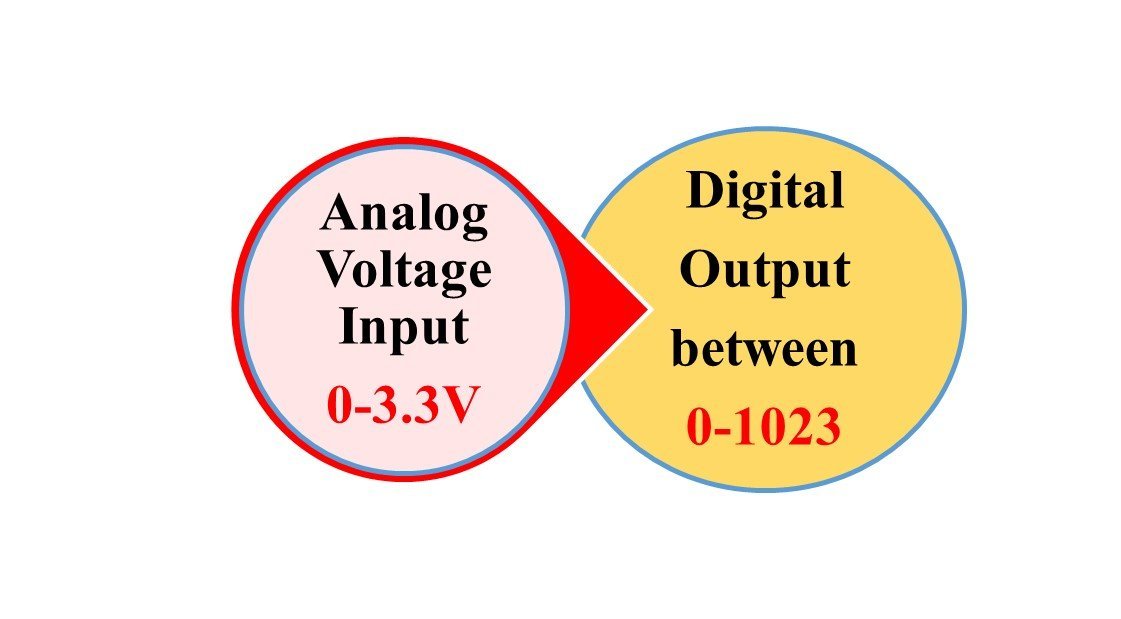
In ESP8266 analog values are read through varying voltage values between 0-3.3V. The voltage which we obtain is then assigned a value between 0-1023. This means the maximum value 1023, corresponds to a 3.3V and a value of 0 corresponds to 0V. Any in-between corresponding values will also get assigned accordingly.
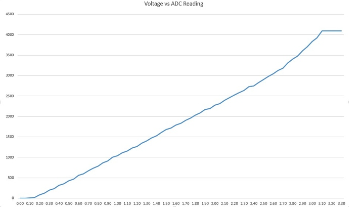
However, there is a slight disadvantage. ADC module is not extremely sensitive to changes in values. It is non-linear in nature. Thus very close values will correspond to similar voltages. For example, 3.3V and 3.2V will both correspond to the value of 1023. The following graph shows the non-linear relationship between the voltage value and the ADC reading.
ESP8266 ADC Channel
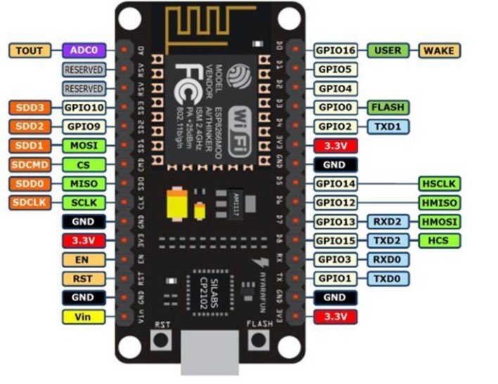
ESP8266 has a single analog pin namely ADC0 which is usually printed A0 on the board.
- ADC0: A0
The following diagram shows the analog pin for ESP8266.
The table below summarizes the ADC properties for ESP8266 NodeMCU
| Resolution | 10 bit |
| Voltage | 0-3.3V |
| Assigned Value | 0-1023 |
| Analog Pin | ADC 0 (A0) |
| Changing Resolution | Cannot change |
Reading Analog Inputs with ESP8266 using Arduino IDE
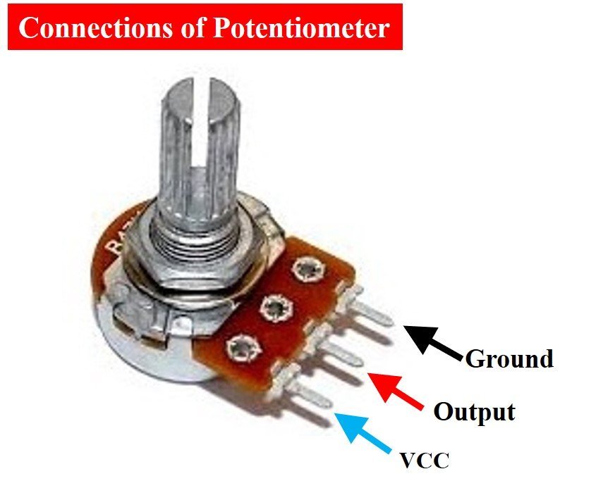
We will now learn how to read the analog inputs from the ESP8266 board using a variable resistor i.e. a potentiometer. The following diagram shows the connections of the potentiometer. The centre terminal gives the output and the two terminals on the sides are provided VCC and ground respectively.
We will connect the potentiometer with the analog pin A0 of our ESP8266 board whose position we learned previously and then measure its voltage. By turning the upper knob of the potentiometer, variable input voltages would be supplied which would be converted to their corresponding digital values through the ADC module in our ESP8266 board. The following components are required to perform this procedure:
Required Components:
- ESP8266 board
- Breadboard
- Potentiometer
- Connecting Wire
ESP8266 with Potentiometer Connection Diagram
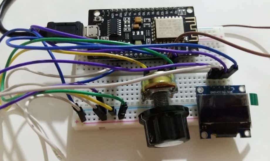
The below picture shows the schematic for the ESP8266 module with a potentiometer. Assemble your circuit as follows:
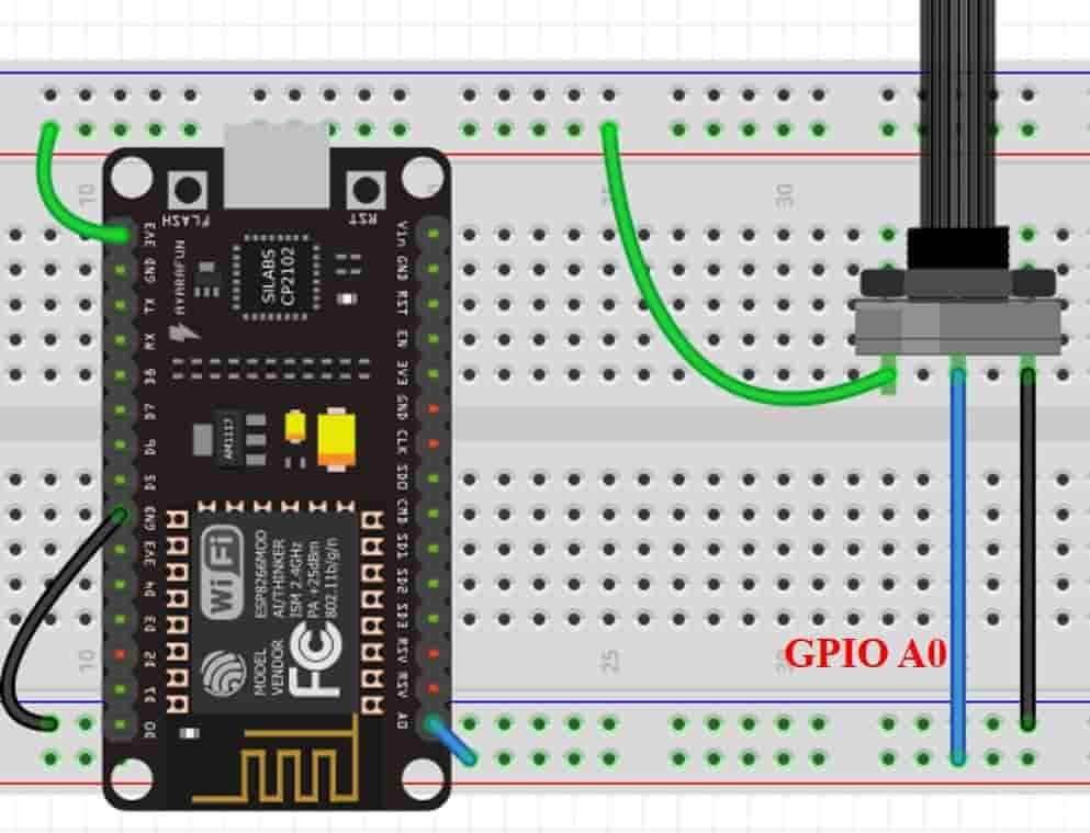
As we can see, the one terminal of the potentiometer is powered by 3.3V (green), the centre terminal is connected to GPIO pin (blue) and the last one is grounded (black). For ESP8266 the blue wires connect the GPIO0 which is ADC0.

Arduino Sketch: Read Analog Values
Open your Arduino IDE and go to File > New to open a new file. Copy the code given below in that file and save it.
This sketch will be able to display ADC readings in the serial monitor while we turn the potentiometer knob to provide variable voltage to the A0 pin.
const int ADC_pin = A0;
int sensor_reading = 0;

void setup() {
  Serial.begin(115200);
}

void loop() {
  sensor_reading = analogRead(ADC_pin);
  Serial.print("ADC reading = ");
  Serial.print(sensor_reading);

  delay(1000);
}
First, we will define two variables. One will hold the ADC pin A0 that we will connect with the potentiometer. The other will be called ‘sensor_reading’ and will save the ADC values. It is initially set to 0.
const int ADC_pin = A0;
int sensor_reading = 0;
Inside the setup() function, we will open the serial communication at a baud rate of 115200.
void setup() {
  Serial.begin(115200);
}
Now, inside the infinite loop() function, we will first find out the ADC value according to the varying voltage using analogRead(). We will pass the ADC pin connected to the potentiometer as an argument inside it. This will be stored in the integer variable we defined previously ‘sensor_reading.’
sensor_reading = analogRead(ADC_pin);Next, we will print these readings in the serial monitor after every 1 second.
Serial.print("ADC reading = ");
Serial.print(sensor_reading);

delay(1000);
Demonstration
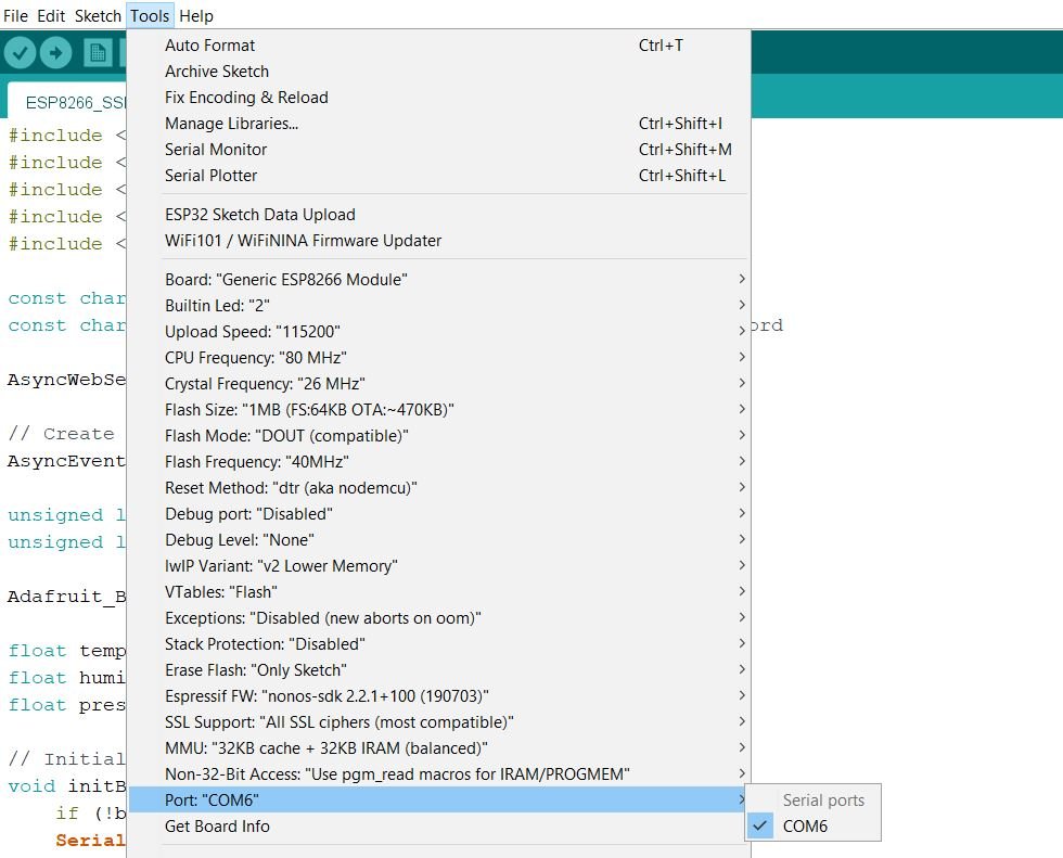
Choose the correct board and COM port before uploading your code to the ESP8266 NodeMCU board. Go to Tools > Board and select ESP8266 NodeMCU Module.

Next, go to Tools > Port and select the appropriate port through which your board is connected.
Now click on the upload button to upload code to ESP8266 NodeMCU. After that open the Arduino serial monitor and press the enable button on ESP8266 NodeMCU:

Open the serial monitor and set the baud rate to 115200. You will be able to see all the different ADC readings as you rotate the knob of the potentiometer.

Analog Voltage Measurement ESP8266 and displaying on OLED display
In the previous section, we have seen how to convert an analog signal into a digital value using Arduino IDE with ESP8266. Similarly, we can also convert the measured digital value back into voltage by multiplying digital value with the resolution of ADC which is 3.3/1023 for ESP8266. Now let’s see an example to measure analog voltage signal ESP8266.
In this section, we will see how to display analog voltage values on a 0.96 SSD1306 OLED display using ESP8266 NodeMCU and Arduino IDE.
Installing OLED Libraries in Arduino IDE
To use the OLED display in our project, we have to install the Adafruit SSD 1306 library and Adafruit GFX library in Arduino IDE. Follow the steps below to successfully install them.
Open Arduino IDE and click on Sketch > Library > Manage Libraries. Type ‘SSD1306’ in the search tab and install the Adafruit SSD1306 OLED library.

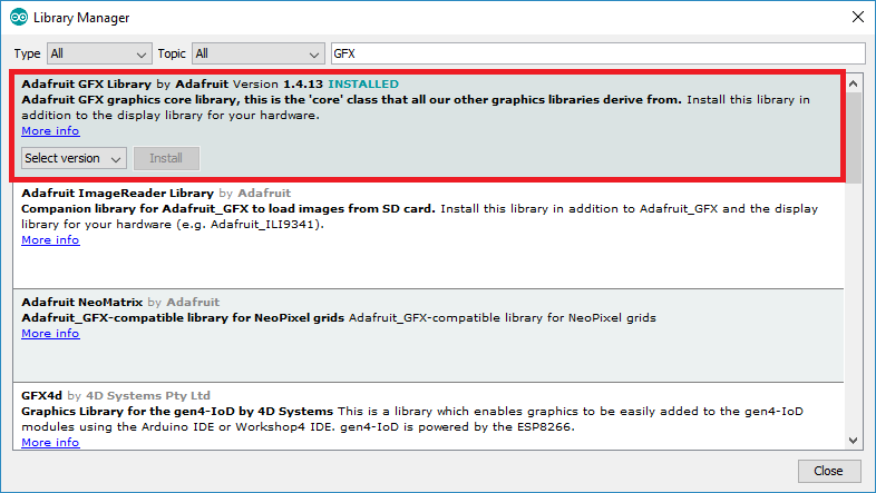
We will also require the Adafruit GFX library which is a dependency for SSD1306. Type ‘Adafruit GFX’ in the search tab and install it as well.
After installing the libraries, restart your IDE.
Connection Diagram– OLED with ESP8266 and Potentiometer
Required Components:
- ESP8266 board
- Potentiometer
- 0.96-inch SSD 1306 OLED Display
- Breadboard
- Connecting Wires
Connecting SSD1306 OLED Display with ESP8266
The OLED display has 4 terminals which we will connect with the ESP8266 board. As the OLED display requires an operating voltage in the range of 3.3-5V hence we will connect the VCC terminal with 3.3V which will be in common with the ESP8266 board. SCL of the display will be connected with the SCL pin of the module and the SDA of the display will be connected with the SDA of the module. By default, the I2C pin in ESP8266 for SDA is GPIO4 and for SCL is GPIO5. The ground of both the devices will be held common. The connections between the two devices can be seen below.
| ESP8266 | SSD1306 OLED Display |
| 3.3V | VCC |
| GPIO4 (D2) | SDA |
| GPIO5 (D1) | SCL |
| GND | GND |
The I2C pins stated above are set in default. If you want to use any GPIO pins for I2C, you will have to set it in code using SoftI2C().
Assemble the circuit as shown in the schematic diagram below:
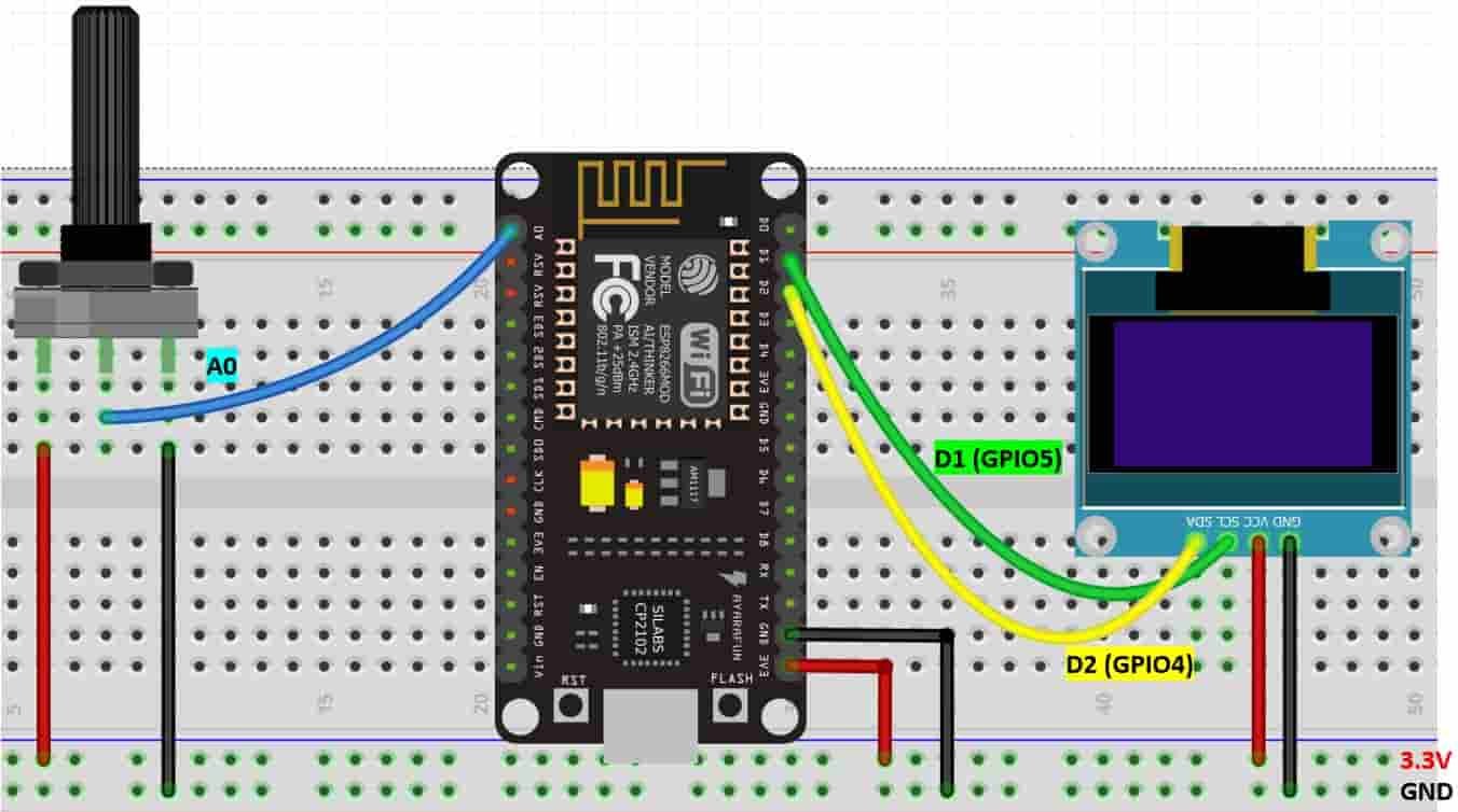
As you can see above, we have connected all the VCC terminals with a 3.3V power supply. The middle pin of the potentiometer is connected with A0 of the ESP8266 board. The SCL terminal of the OLED is connected with D1 (GPIO5) and the SDA terminal of the OLED is connected with D2 (GPIO4). The grounds of all three devices are common.
Arduino Sketch (Displaying ADC and Voltage Readings on OLED Display)
Open your Arduino IDE and go to File > New. A new file will open. Copy the code given below in that file and save it.
This sketch will display the ADC values and the corresponding analog voltage on the Serial Monitor as well as on the OLED.
#include <Adafruit_GFX.h>
#include <Adafruit_SSD1306.h>

const int ADC_pin = A0;
int sensor_reading = 0;
float analog_voltage;

Adafruit_SSD1306 display = Adafruit_SSD1306(128, 64, &Wire, -1);

void setup() {
  Serial.begin(115200);

   if(!display.begin(SSD1306_SWITCHCAPVCC, 0x3C)) {
  Serial.println(F("SSD1306 allocation failed"));
  for(;;);}
  delay(2000);
display.clearDisplay();
display.setTextColor(WHITE);
}

void loop() {
  display.setCursor(0,0);
  display.setTextSize(1);
  display.clearDisplay();

  sensor_reading = analogRead(ADC_pin);
  Serial.print("ADC reading = ");
  Serial.println(sensor_reading);
  analog_voltage = sensor_reading * 3.3 / 1023;
  Serial.print("Volatge reading = ");
  Serial.println(analog_voltage);


  display.setTextSize(1);
  display.setCursor(0,0);
  display.print("ADC reading: ");
  display.setTextSize(2);
  display.setCursor(0,10);
  display.print(sensor_reading);

  display.setTextSize(1);
  display.setCursor(0,35);
  display.print("Voltage: ");
  display.setTextSize(2);
  display.setCursor(0,45);
  display.print(analog_voltage);
  display.print(" ");
  display.setTextSize(2);
  display.setCursor(60,45);
  display.print("V");

  Serial.println();
  display.display();
  delay(1000);

}
How the Code Works?
Firstly, we will include the OLED libraries that we previously installed for the proper functionality of the OLED display.
#include <Adafruit_GFX.h>
#include <Adafruit_SSD1306.h>
Secondly, we will define three variables. One will hold the ADC pin A0 that we will connect with the potentiometer. The second one will be called ‘sensor_reading’ and will save the ADC values. It is initially set to 0. For the third variable we will define it as a floating type to save the values for the analog voltage.
const int ADC_pin = A0;
int sensor_reading = 0;
float analog_voltage;
Now, we will create an object named display which will be handling the OLED display and specifying the width, height, I2C instance (&Wire), and -1 as parameters inside it.’ -1′ specifies that the OLED display which we are using does not have a RESET pin. If you are using the RESET pin then specify the GPIO through which you are connecting it with your development board.
Adafruit_SSD1306 display = Adafruit_SSD1306(128, 64, &Wire, -1);Inside the setup() function, we will open the serial communication at a baud rate of 115200.
void setup() {
  Serial.begin(115200);
}
Moreover, we will also initialize the OLED display by using display.begin(). Make sure you specify the correct address of your display. In our case, it is 0X3C.
if(!display.begin(SSD1306_SWITCHCAPVCC, 0x3C)) {
  Serial.println(F("SSD1306 allocation failed"));
  for(;;);}
Then, we will clear the buffer by using clearDisplay() on the Adafruit_SSD1306 object. Additionally, we will set the colour of the text as white.
display.clearDisplay();
display.setTextColor(WHITE);
Now, inside the infinite loop() function, we will set the position of the cursor of the OLED and also set the text size. The clearDisplay() function will wipe off the previous readings from the display after each loop() so that new ones can be printed.
  display.setCursor(0,0);
  display.setTextSize(1);
  display.clearDisplay();
Obtaining ADC and Voltage Readings
Then we will first find out the ADC value according to the varying voltage using analogRead(). We will pass the ADC pin connected to the potentiometer as an argument inside it. This will be stored in the integer variable we defined previously ‘sensor_reading.’
sensor_reading = analogRead(ADC_pin);Next, we will print these readings in the serial monitor after every 1 second.
Serial.print("ADC reading = ");
Serial.print(sensor_reading);
Next we will calculate the analog voltage we multiplying the ADC digital value with resolution of ESP8266 ADC which is 3.3/1023. It will provide output in the form of voltage.
 analog_voltage = sensor_reading * 3.3 / 1023;
  Serial.print("Volatge reading = ");
  Serial.println(analog_voltage);
Displaying Text on OLED
Now, we will display these two readings on the OLED display. First, we will set the size of the text using setTextSize() and pass the size as a parameter inside it. 1 denotes the smallest size and it increases relatively after incrementing it. We have set the font size as ‘1’ for the headings and ‘2’ for the actual values. Whenever we increase the size by +1, the pixel resolution of the text increases by 10 in height.
We will use the setCursor() function to denote the x and the y axis position from where the text should start. We have passed (0,0) as the parameter hence the text starts from the upper left corner. The first parameter is the x-axis position that (+x) increases towards the right. The second parameter is the y-axis position that (+y) increases downwards. We will set the cursor to new positions for each text.
Then by using println() we will pass the text which we want to display on the OLED. Just specify it like you do when printing strings/variables of serial objects.
Finally, we will call the display() function on the display object so that the text displays on the OLED.
display.setTextSize(1);
  display.setCursor(0,0);
  display.print("ADC reading: ");
  display.setTextSize(2);
  display.setCursor(0,10);
  display.print(sensor_reading);

display.setTextSize(1);
  display.setCursor(0,35);
  display.print("Voltage: ");
  display.setTextSize(2);
  display.setCursor(0,45);
  display.print(analog_voltage);
  display.print(" ");
  display.setTextSize(2);
  display.setCursor(60,45);
  display.print("V");

  Serial.println();
  display.display();
  delay(1000);
Demonstration
Choose the correct board and COM port before uploading your code to the ESP8266 NodeMCU board. Go to Tools > Board and select ESP8266 NodeMCU Module.
Next, go to Tools > Port and select the appropriate port through which your board is connected.
Now click on the upload button to upload code to ESP8266 NodeMCU. After that open the Arduino serial monitor and press the enable button on ESP8266 NodeMCU:
The OLED display will start showing values for ADC and its corresponding voltage in volts. Rotate the knob of the potentiometer and see the values changing from 0-1023 for ADC and 0-3.3V for voltage.
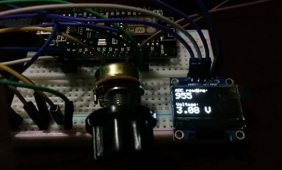
Open the serial monitor and set the baud rate to 115200. You will be able to see all the different ADC and voltage readings as you rotate the knob of the potentiometer.

Conclusion
In conclusion, we have learned about ESP8266 NodeMCU ADC and how to get readings of both ADC and analog voltage using Arduino IDE. We used a potentiometer to supply varying voltage to the ESP8266 A0 pin and then read the signal obtained. Likewise, we were also able to display the readings on an OLED display.
We have a similar guide for both ESP32 and ESP8266 NodeMCU in Micro Python as well:
ESP32/ESP8266 ADC with MicroPython – Measure Analog Readings
Your ADC reading vs input voltage chart appears to be for a 12 bit ESP32 rather than the 10 bit ESP8266.