In this tutorial, we will learn how to configure and handle interrupts in ESP32 and ESP8266 development boards using MicroPython. We will demonstrate this through an example with a PIR sensor and an LED.
Recommended Components
The following components are used in this project or are helpful for getting started with MicroPython on ESP32 and ESP8266.
| Component | How it’s used in this project | Buy on Amazon |
|---|---|---|
| ESP32 Development Board (DevKit V1) | The ESP32 board flashed with MicroPython firmware. | Check Price |
| ESP8266 NodeMCU (ESP-12E) | The ESP8266 NodeMCU running the same MicroPython code. | Check Price |
| Micro USB Cable | Programs and powers the board from your PC. | Check Price |
| PIR Motion Sensor (HC-SR501) | Detects motion and triggers the external interrupt. | Check Price |
| Breadboard | Holds the sensor and LED for prototyping. | Check Price |
| Jumper Wires | Connect the sensor and LED to the board. | Check Price |
As an Amazon Associate we earn from qualifying purchases. Prices and availability are accurate as of the date/time indicated and are subject to change.
Prerequisites
In order to completely understand this tutorial, you should know that how to use ESP32 and ESP8266 boards with MicroPython using any MicroPython supported IDE such as uPyCraft IDE and Thonny IDE. If you do not have prior understanding with these IDE’s, you should read these getting started guides:
If you are using Thonny IDE, you can check this getting started guide:
First let’s see an introduction of interrupts and what are the applications of interrupts, especially, in embedded systems.
Interrupts Introduction?
Interrupts are used to handle events which do not happen during sequential execution of a program. For example, we want to perform certain tasks and these tasks executes sequentially in your MicroPython program. But there are few tasks which only executes when a special event occurs such as an external trigger signal to the digital input pin of a microcontroller.
An external interrupt or a ‘hardware interrupt’ is caused by the external hardware module. For example, there is a Touch Interrupt which happens when touch is detected and a GPIO interrupt when a key is pressed down.
Different Between Sequential and Event Driven Execution?
In our previous tutorial, where we controlled the LED connected to one of the GPIO pins of ESP32 and ESP8266 with the help of a push button. This push button was connected with a digital input pin of ESP32/ESP8266. In that MicroPython code, we must continuously monitor the state of digital input pin to which push button connected. In response to the state of digital input, we were controlling the LED. But one main disadvantage of this method was that we must check the state of digital input every time during sequential execution even if the user does not press the push button. It is a waste of microcontroller processing power and resources.
What happens when Interrupt Occurs?
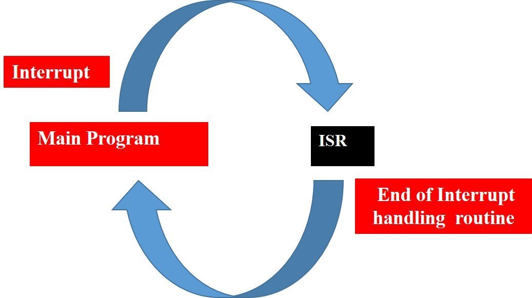
With interrupt, we do not need to check the continuously check the state of digital input pin. When an interrupt occurs (a change is detected), the processor stops the execution of the main program and a function is called upon known as ISR or the Interrupt Service Routine. The processor then temporarily works on a different task (ISR) and then gets back to the main program after the handling routine has ended. This is shown in the figure below.
An example can be that of pressing a push button or motion detection with a PIR Sensor. In both cases, push button or a PIR motion sensor can be used to trigger an interrupt. Therefore, when an external event occurs, the processor stops what it is doing and executes the interrupt service routine which we define for the respective event. After that, it returns to the current program. External Interrupts are extremely useful because with their help we do not have to constantly monitor the digital input pin state.
ESP32 and ESP8266 Interrupt Pins
Interrupt Pins ESP32
For ESP32 we can use all GPIO pins for external interrupt except for GPIO6, GPIO7, GPIO8, GPIO9, GPIO10 and GPIO11. The diagram below shows the pin out of the GPIO pins in ESP32 that can be used.

Interrupt Pins ESP8266
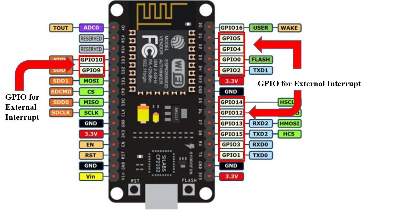
For ESP8266, we can use all the GPIO pins except for GPIO16 to generate external interrupt. The figure below shows the GPIO pins that can be used.
Configuring Interrupts in MicroPython
Now let us look at how to set up external interrupts in our ESP32 and ESP8266 development boards using MicroPython. The following steps need to be followed.
Defining an Interrupt Handling Function
def handle_interrupt(pin):The interrupt handling function is defined in an extremely easy way. It needs to be simple as that the processor is able to return back to the main program swiftly. This can be achieved by making a global variable which can be accessed by all in our case we will use the ‘Pin’ variable. The pin variable will act as a parameter inside our interrupt handling function as follows handle_interrupt(pin). This line shows the GPIO associated with the pin which caused an interrupt to occur.
Setting the GPIO as an input that will act as an interrupt pin
input=Pin(2,Pin.IN)To get the value of a GPIO, we will create a Pin object and set it as an input using ‘Pin.IN’ as the second argument in our Pin() class. In the example above the input is on GPIO2 which we specified in the first argument. This is stored in the object ‘input’. You can choose whatever object name you want to.
Attaching an Interrupt to the Pin
input.irq(trigger=Pin.IRQ_RISING, handler=handle_interrupt)
In this step we will attach the interrupt to the pin which we specified before by using the irq() method. In this method we pass two arguments namely trigger and handler:
- trigger: There are three different conditions we can choose from.
Pin.IRQ_RISING : This is used to trigger the interrupt when the pin goes from LOW to HIGH.

Pin.IRQ_FALLING: This is used to trigger the interrupt when the pin goes from HIGH to LOW.

Pin.IRQ_FALLING|Pin.IRQ_RISING: This is used to trigger the interrupt when any change is detected meaning it can be both HIGH-LOW or LOW-HIGH.

MicroPython also supports trigger event on low or high level using Pin.IRQ_LOW_LEVEL and Pin.IRQ_HIGH_LEVEL, respectively.
- handler: handle_interrupt() function is passed as the second parameter in the irq() method. This function is called whenever an interrupt is detected.
External Interrupt using a PIR Sensor in ESP32 and ESP8266
Now we will learn how to handle interrupts in the ESP32 and ESP8266 boards using a PIR Sensor and an LED. For demonstration purpose, we will use a PIR motion detector sensor. When a PIR sensor will detect motion, we will turn on the LED for 5 seconds as shown in figure below:
The following components are required:
- ESP32/ ESP8266 development board
- One PIR Sensor
- One 5mm LED
- One 220 ohm resistor
- One 10k ohm resistor
- Breadboard
- Connecting Wires
PIR Motion Sensor with ESP32 and ESP8266
We will be using the same GPIO pins for both ESP32/ESP8266 modules. Assemble your circuit as shown in the diagram below for ESP8266 and ESP32 respectively:
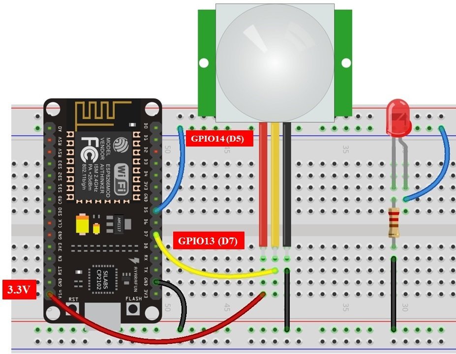

ESP32 and ESP8266 Schematic Diagrams with PIR Sensor
In the above schematics, we can see that GPIO14 is connected with the anode pin of LED, and the cathode pin is connected with the common ground through the 220 ohm resistor.
The PIR Sensor which we are using in this tutorial consists of three pins. Two of them are power supply pins such as Vcc and ground pins. We can power PIR motion sensor directly from ESP32 and ESP8266 power pins as shown in above schematic diagram. The center pin is an output pins which provides a active high pulse whenever motion is detected. Otherwise, this pin remains active low. That means a rising edge occurs when a PIR sensor detects motion. We can detect this rising edge with the help of interrupt pins of ESP32 and ESP8266.
How PIR sensor works with External Interrupt?
The PIR Sensor acts as an source for the external interrupt. That means we connect the output of PIR sensor with the GPIO pin of ESP32 and ESP8266. Furthermore, we attach the rising edge triggered interrupt to this GPIO pin. That means this GPIO pin will trigger the interrupt whenever it will sense rising edge on its input.

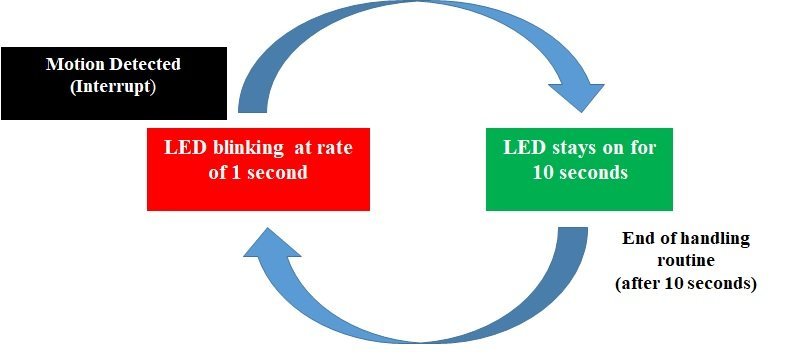
Initially, the status LED will blink after a delay of 1 seconds. When a PIR sensor detects motion, an external interrupt is caused, the LED will stay on for 10 seconds and then return back to its normal blinking stage (on/off with a delay of 1 second). The following figure shows the process.
Interrupt MicroPython Script
Create a new file in uPyCraft or Thonny IDE and copy this code to your newly created file. After that download and run this MicroPython script on ESP32 and ESP8266.
from machine import Pin       #importing classes
from time import sleep    #Import sleep from time class

Motion_Detected = False  #Global variable to hold the state of motion sensor

def handle_interrupt(Pin):           #defining interrupt handling function
 global Motion_Detected
 Motion_Detected = True

led=Pin(14,Pin.OUT)   #setting GPIO14 led as output
PIR_Interrupt=Pin(13,Pin.IN)   # setting GPIO13 PIR_Interrupt as input

#Attach external interrupt to GPIO13 and rising edge as an external event source
PIR_Interrupt.irq(trigger=Pin.IRQ_RISING, handler=handle_interrupt)

while True:
  if Motion_Detected:
   print('Motion is detected!')
   led.value(1)
   sleep(20)
   led.value(0)
   print('Motion is stopped!')
   Motion_Detected = False
  else:
   led.value(1)    #led is on
   sleep(1)        #delay of 1 second
   led.value(0)    #led is off
   sleep(1)        #delay of 1 second
How Code Works?
Importing MicroPython Libraries
Now, let’s see the working of a MicroPython script. To use interrupts in MicroPython, We should import the GPIO class from machine module. Because GPIO class contains methods to configure interrupts for ESP32 and ESP8266. We should also import the sleep module to insert delay in our MicroPython script.
from machine import Pin
from time import sleep
Create Global Variable MicroPython
Next, create a global variable with any name to indicate the state of PIR motion sensor. We have defined a global variable with a name of “Motion_Detected” and the value of this global variable can be either True or False. To indicate the state of PIR sensor, we will set the global variable value to True whenever an interrupt occurs due to motion detected by PIR sensor. Initially set the value of this variable to False.
Motion_Detected = False #Global variable to hold the state of motion sensorDefine Interrupt Handler Function
Next, we define the interrupt handling function about which we learned in the interrupt handling section. The pin parameter to the interrupt handling function such as handle_interrupt(), is an instance of the pin class. This instance shows which GPIO pin has caused an interrupt.
def handle_interrupt(Pin):           #defining interrupt handling function
 global Motion_Detected
 Motion_Detected = True
Inside the interrupt handler function, we set the global variable “Motion_Detected” to a logic True value and we will use this value inside the while loop to execute code which executes only when an interrupt occurs. You must be wondering why we are not executing the code related to PIR sensor inside the handle_interrupt() function instead of executing it inside the while() loop. This is because it is recommended to keep interrupt service routines as short as possible to improve interrupt latency.
That means we should execute the minimum possible number of instructions inside the interrupt callback function. That is why we have only changed the state of the “Motion_Detected” variable inside the ISR and will perform the remaining functionality inside the main code.
Note: “Motion_Detected” is a global variable. Therefore, we can use it throughout the execution of the program.
Create Pin Instances
Create two instances of Pin class one for output LED and the second one for external interrupt input pins.
To set a GPIO on or off, we will set it as an output. The first argument in the Pin() class is the pin number on which we are configuring the output. The output is on GPIO14 which is connected to the LED. The second argument shows the pin mode e.g. digital input or digital output mode. As we are configuring pin 14 as digital output we gave, specifies it as ‘Pin.Out’. This is stored in the object ‘led’
led=Pin(14,Pin.OUT) //setting GPIO14 led as outputTo enable external interrupt on GPIO13, create a Pin object (PIR_Interrupt ) and set it as a digital input pin using ‘Pin.IN’ as the second argument in our Pin() method. The input is on GPIO13 which we specified in the first argument and is connected to the PIR Sensor.
PIR_Interrupt=Pin(13,Pin.IN) # setting GPIO13 PIR_Interrupt as inputAttach Interrupt to GPIO Pin
Now as we have defined our input/output GPIOs. The next step is to attach the interrupt to the GPIO13 pin. As we want the PIR Sensor rising edge pulse to trigger the interrupt which acts as an input to GPIO13 as follows:
#Attach external interrupt to GPIO13 and rising edge as an external event source
PIR_Interrupt.irq(trigger=Pin.IRQ_RISING, handler=handle_interrupt)
This irq() method is used to configure the interrupt handler which will be called when the trigger event for that particular interrupt happens. In our case, this trigger event is an external rising edge on the GPIO13 pin.
We set the irq() method’s first argument as ‘trigger=Pin.IRQ_RISING.’ This means we want the interrupt to happen when the transition of signal happens from LOW to HIGH state namely rising edge of signal.
Motion Detection Code
Inside the loop, we check if the global variable is True. If it is True, we turn on the LED for 10 seconds and after that turn off the LED.
 if Motion_Detected:
   print('Motion is detected!')
   led.value(1)
   sleep(20)
   led.value(0)
   print('Motion is stopped!')
   Motion_Detected = False
If the global variable “Motion_Detected” is False. LED stays ON for one seconds and turns OFF again for one second. This shows a constant blinking effect of the led after every 1 second.
 led.value(1)    #led is on
   sleep(1)        #delay of 1 second
   led.value(0)    #led is off
   sleep(1)        #delay of 1 second
Note: “Motion_Detected” variable will become Ture only when motion is detected and in response interrupt handling function executes which will set this variable value to True.
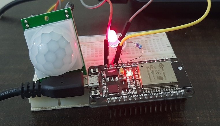
Now create a new file in uPyCraft IDE or Thonny IDE and download this MicroPython Script to ESP32 or ESP8266. You will see that the LED blinks with a rate of one second when no motion detected and when PIR sensor detects motion, LED stays on for 10 seconds as follows:
Video Demo:
In this tutorial, we learned about how to handle external interrupts in ESP32/ESP8266 in Micro python using a PIR Sensor.
You may also like to read:
- ESP32 and ESP8266 GPIO Programming with MicroPython
- Push Button with ESP32 and ESP8266 using MicroPython
- ESP32/ESP8266 ADC with MicroPython
- MicroPython: PWM with ESP32 and ESP8266
- HC-SR505 PIR motion sensor Module
- PIR sensor interfacing with pic microcontroller
- PIR sensor interfacing with Arduino
- Home security system using PIR sensor and GSM module
Note that in defining the three types of interrupt trigger, the third type name was omitted. How do you specify that type of interrupt?
Thanks, we will fix it. We can differentiate between external caused by different pins using the input instance of pin class parameter to interrupt the handler function. In our article, we learned to configure external interrupts only.
How can one use isr in a class of python and use it in an object.
Thanks