Home security system using PIR sensor and GSM module: Hi Everyone I am all of you are fine and doing well. Today’s project is about Gsm based home security system using PIR sensor, SIM900A gsm module and pic microcontroller. In this sms based home alarm system, we are using PIR sensor as motion detector module and GSM module will be used to send sms to home owner number whenever motion sensor detect any motion in home. Owner can switch on this home security module when he is going out for work and switch it off when he/she is inside home. But it is totally dependent on user how he/she wants to use it. I have included two new features in this project. User can either select call option or message option on his number when he/she detect any motion in home. I will describe it in more detail in later part of this article. So it was the introduction of home security system or motion detection using PIR sensor. I have used pic microcontroller in this project. If you are new to pic microcontroller programming, I recommend you to check this pic tutorials article, It will help you to get start with pic microcontroller programming for home security system.
Components of wireless home security system
Followings are the main components used in home security system. I will explain each component one by one briefly. So now first start with pic microcontroller.
- PIC18F452 microcontroller : In this project PIC18F452 pic microcontroller is used. It received data from PIR sensor with the help of built it analog to digital converter. PIR sensor output voltage changes whenever it detect any motion. Pic microcontroller measures this voltage. If this measured voltage is greater than a specified limit, PIC microcontroller sends commands to GSM module. GSM module send sms or make call according to selection of user.

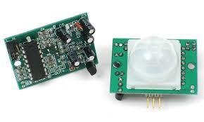
- PIR sensor: PIR sensor is used to sensor motion in home. PIR sensor has three pin Vcc, GND and out pin. Vcc pin is connects with 5 volt power supply and ground pin connects with Ground pin of power supply. Out pin is connected with analog to digital converter module of pic microcontroller. Output voltage changes at the output pin of PIR sensor whenever it detects any motion. PIC microcontroller measures this voltage and if voltage is greater than specific value, microcontroller sends AT commands to GSM module SIM900A to send sms to user or make call to user.

- SIM900A GSM module: GSM module used in this project to either send sms to user or to make call to user on his/her cell number. GSM module communicate with pic microcontroller through AT commands. you should make sure to connect GSM module with pic microcontroller which has same operating voltages as operating voltages of pic18f452. If your GSM module works on 5 volt, you can connect it directly with PIC18F452. Because PIC18F452 also works on same operating voltages. But if your GSM module works on 3.3 volt, you need to use a interfacing circuit between them. GSM module communicate with pic microcontroller through serial communication UART.


so these are the main components used in home security system or sms based home alarm system. Now lets move to circuit diagram of gsm based home security system after the I will explain programming part of this project.
Circuit diagram of Home security system using PIR sensor and GSM module
Circuit diagram of sms or call bed home alarm system is given below. I have already provided a description of each components used in this project above. So this circuit diagram is self explanatory except few components. Two switches are used for selection purpose. It provides option to user either he/she want to receive sms or call upon detection of motion in home. If you use press switch one, he will receive sms and if you user press switch he will receive call on his number. Rest is just a rest circuit and resistors used in this project as a current limiting components. Two switches are interfaced with pic18f452 on PORTE bit number one and bit number 2. This port is used as digital input pin. check this article on how to digital input output ports of microcontroller. So this is a circuit diagram and working of this home security system using pic microcontroller. 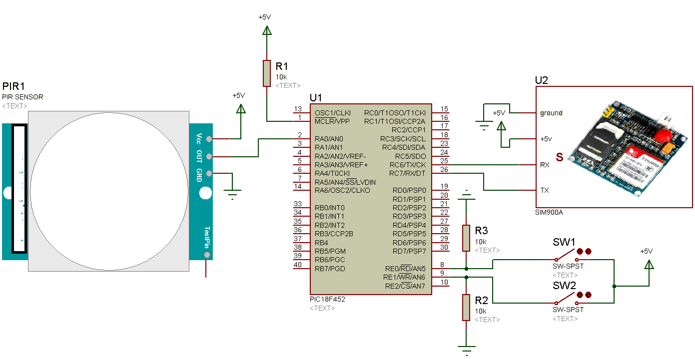
Video demonstration gsm based home alarm system
Code gsm based home security system
Code for this project is written using Mikro c for pic. To write code for this project, you should know how to measure analog voltage with pic microcontroller and how to send AT commands through serial communication. you should also know about which AT commands of SIM900A are used to sens sms and which AT commands are used to make call.
int adc;
char AT[]="AT"; // To initialize mode
char noecho[]="ATE0"; // To stop echo
char mode_text[]="AT+CMGF=1"; // to set text mode
char char_mode[]="AT+CSCS=\"GSM\""; // to set character mode
char param[]="AT+CSMP=17,167,0,0"; // set the parameter of character
char mobile_no[]="AT+CMGS=\"enter your number here\""; //use to set receinpent number and mesg
char terminator=0x1A; // chartacter form of control + z terminator character
char mesg[]="Someone is in your home"; // mesg we want to send
void send_to_modem(char *s) //function to write anything serially
{
while(*s)
UART1_WRITE(*s++);
UART1_WRITE(0X0D);
}
void send_to_modem1(char *s)
{
while(*s)
UART1_WRITE(*s++);
}
void send_sms()
{

send_to_modem1(mesg);
delay_ms(100);
uart1_write(terminator);
delay_ms(1000);
}
void main()

{
OSCCON.IRCF0=0;
OSCCON.IRCF1=1;
OSCCON.IRCF2=1;
ANSELA=0X01;
ANSELB=0X00;
ANSELC=0X00;
ANSELD=0X00;
ANSELE=0X00;
TRISB=0x00;
PORTB=0X00;
delay_ms(1000);
Uart1_init(9600);
ADC_Init();
while(1)
{
PORTB.B0==1;
delay_ms(2000);
PORTB.B0=0;
delay_ms(2000);
adc = adc_read(0);
if (adc>=700)
{
PORTD.B1==1;
send_to_modem(AT);
delay_ms(1000);
send_to_modem(noecho);
delay_ms(1000);
send_to_modem(mode_text);
delay_ms(1000);
send_to_modem(mobile_no);
delay_ms(1000);
send_sms();
PORTD.B1==0;
}


}

}
This is all about home security system using GSM Module and PIC Microcontroller. You may like to check pic microcontrollers projects list.
Great work, can i get the list for all the components
hi please send me Code for this project is written using arduino
PIR SENSOR AND GSM BASED HOME SECURITY SYSTEM USING ARDUINO UNO CODING
dear sir it artical is very use full us.and i have a doubt in the code can you help me ?