This tutorial shows how to generate PWM using Pulse width modulation module of TM4C123 microcontroller. We will learn to generate a square wave of variable frequency and variable duty cycle with TM4C123GH6PM microcontroller PWM generators. For demonstration purposes, we will use TM4C123 Tiva Launchpad which comes with TM4C123GH6PM MCU. Hence, throughout this article, we use TM4C123 to refer to TI microcontrollers belongs to this series.
Recommended Components
The following components are used in this project or are helpful for getting started with TM4C123 Tiva C LaunchPad development.
| Component | How it’s used in this project | Buy on Amazon |
|---|---|---|
| TM4C123G Tiva C LaunchPad | The Tiva C board generating the PWM signals. | Check Price |
| Micro USB Cable | Connects the LaunchPad’s onboard debugger to your PC for programming and power. | Check Price |
| 5mm LED | Optional external LED for trying the PWM fading demo off-board. | Check Price |
| Resistor Kit (220Ω) | Current-limiting resistor for an external LED. | Check Price |
| Breadboard | Solderless breadboard for building the circuit. | Check Price |
| Jumper Wires | For wiring an external LED or oscilloscope probe to the PWM pin. | Check Price |
As an Amazon Associate we earn from qualifying purchases. Prices and availability are accurate as of the date/time indicated and are subject to change.
Pre-requisites:
- How to Download and Install Keil uVision for ARM and 8051
- Getting started with Keil uVision: Write your first Program for Tiva LaunchPad
TM4C123 PWM Modules
This microcontroller has two PWM blocks such as PWM0 and PWM1. Further, each PWM block contains four PWM generators and control blocks. Additionally, each PWM generator provides two PWM outputs such as pwmA and pwmB. But these two PWM signals shares the frequency or counter blocks. Hence, two PWM outputs from the same generator will have same frequency but can have different duty cycle or can be used as a complementary output to drive half bridge and full bridge in motor control applications. These complementary outputs also provide programmable dead-band delays.
PWM generator blocks are used to generate PWM signals. On the other hand, control blocks are used to send PWM output signals to the GPIO pins of TM4C123 microcontroller.
Hence, each generator provides 8 PWM channels. Therefore, TM4C123 microcontroller supports total of 16 PWM outputs namely M0PWM_n and M1PWM_n where n = 0 – 7 and M0 – M1 are for module 0 and module 1.
TM4C123 PWM Output Pins
The following table shows the GPIO pins associated with each PWM output signal.
| PWM Channel | TM4C123 GPIO Pins | PWM Generator |
|---|---|---|
| M0PWM0 | PB6 | Module 0 Generator 0 |
| M0PWM1 | PB7 | |
| M0PWM2 | PB4 | Module 0 Generator 1 |
| M0PWM3 | PB5 | |
| M0PWM4 | PE4 | Module 0 Generator 2 |
| M0PWM5 | PE5 | |
| M0PWM6 | PC4/PD0 | Module 0 Generator 3 |
| M0PWM7 | PC5/PD1 | |
| M1PWM0 | PF0 | Module 1 Generator 0 |
| M1PWM1 | PD1 | |
| M1PWM2 | PA6/PE4 | Module 1 Generator 1 |
| M1PWM3 | PA7/PE5 | |
| M1PWM4 | PF0 | Module 1 Generator 2 |
| M1PWM5 | PF1 | |
| M1PWM6 | PF2 | Module 1 Generator 3 |
| M1PWM7 | PF3 |
Now let’s see how to program PWM modules of TM4C123 microcontroller using Keil uvision IDE.
Programming TM4C123 PWM Modules
By default, or on reset, system clock is disabled to all peripherals of TM4C123 microcontroller and so is to PWM modules. The clock is disabled to save power. But the clock source can be enabled to each peripheral whenever we want to use it. Therefore, first we must enable the clock source to PWM modules.
Enabling Clock to PWM Modules
RCGCPWM register is used to enable clock source to both PWM modules. Setting Bit0 and Bit1 of RCGCPWM register enables the clock and clearing these bits disable the clock to both modules.
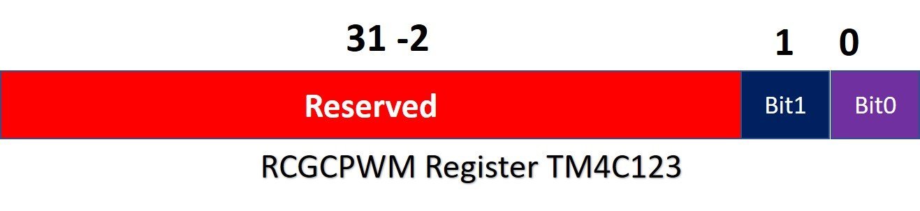
SYSCTL->RCGCPWM |= (1<<0); /*enable clock source to PWM0 module */
SYSCTL->RCGCPWM |= (1<<0); /* enable clock source to PWM0 module */
PWM Clock Configuration
RCGCPWM register selects operating frequency of TM4C123 microcontroller directly as a clock for PWM modules. Run-Mode clock configuration (RCC) register is used to scale down frequency for PWM modules. But the question is why do we need to scale down frequency? Because sometimes we need to generate a low frequency square wave from these PWM modules. If PWM generators operate at higher operating frequency, we will not be able to get low frequency PWM. We will take an example in coming sections of this tutorial.

RCC register acts as a divider between system clock frequency and input frequency to PWM modules. The clock divisor options can be selected with bit20 (USEPWMDIV) and bits 19-17 (PWMDIV) of RCC register. The bit20 (USEPWMDIV) selects either we want to use direct system frequency or pass it through a frequency divisor. Setting Bit20 to 1, selects the frequency divisor option. The bits 19-17 selects the divided by options from 2, 4, 8, 16, 32, and 64. The value of PWMDIV bits selects the value of frequency divisor as shown in this table.
Frequecy Divisor Table
The last column of this table shows the PWM modules clock frequencies for all possible divisor values.
| PWMDIV Bits | Divisor value | PWM Moudle Frequency |
|---|---|---|
| 000 | 2 | 8MHz |
| 001 | 4 | 4MHz |
| 010 | 8 | 2MHz |
| 100 | 16 | 1MHz |
| 101 | 32 | 500kHz |
| 111 | 64 | 250kHz |
Enable TM4C123 PWM Generator
As you mentioned earlier, each PWM block contains four generators. These generators also known as counters. They are of 16-bit width.
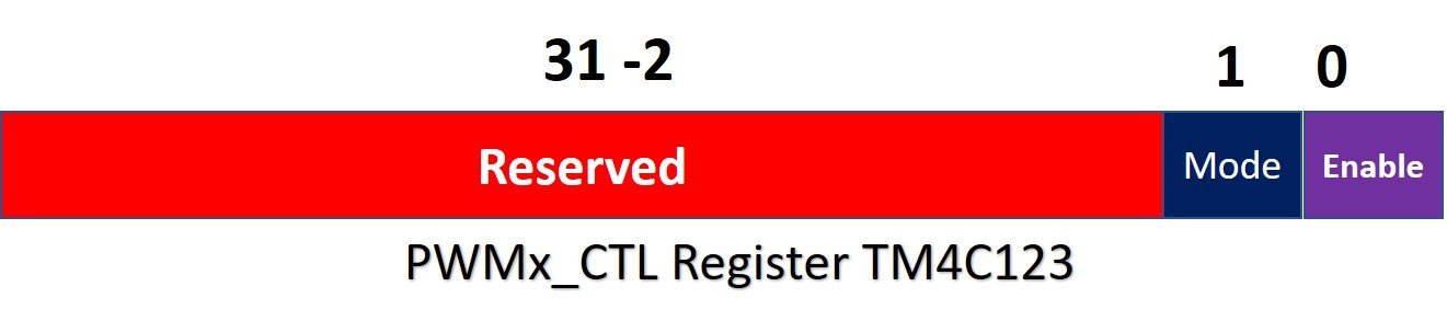
PWMnCTL registers are used to enable each generator for PWM modules.
- Bit0 of the control register is used to enable and disable the generator. Setting this bit enables and clearing disables the generator.
- Bit1 is a mode select bit of counter. Each generator has a 32-bit counter registers. It can be configured either in up-count (Mode bit = 1) or down-count mode (Mode bit = 0).
Each generator has a separate control register. In keil uvision IDE, these registers are names as: PWM0->_0_CTL, PWM0->_1_CTL, PWM0->_2_CTL, PWM0->_3_CTL and similarly for PWM module one.
In up count mode, the counter starts counting from 0 and count up to the load value. When the counter reaches load value, it resets to zero again.
In down count mode, the counter starts counting from load value and keeps decrementing. When the counter reaches zero, it resets to load value again.
Setting TM4C123 PWM Frequency
As we have seen in the last section, the counter register must count up or count down to the load value. The load value must be loaded to the PWMnLOAD register. Each generator has its own load register. For example, for module PWM0, each generator has a separate load register such as PWM0LOAD, PWM1LOAD, PWM2LOAD and PWM3LOAD. Similarly, each generator of PWM1 module also has a separate load register.
Example One
The load value defines the frequency of the PWM signal. For example, we are using PWM0 module and the clock frequency selected for PWM0 module is 8MHz by using a divisor value of 2. Now, we want to generate 10KHz PWM signal with PWM0 module. What will be the value for PWM4LOAD register?
PWM0 Module Clock Period = 1/8Mhz = 0.125µs
M0PWM4 Timer Period = 1/10KHz = 100µs
PWM4LOAD Register value = 100µs / 0.125µs = 800
To generate, 10KHz PWM signal with M0PWM4, we must load 800 to the PWM4LOAD register.
Example Two
Let’s take another example to understand the role of frequency divisor register that we have discussed earlier. For example, we want to generate a 50Hz PWM signal. Now calculate the value for load register by directly using TM4C123 microcontroller operating frequency which is 16MHz.
PWM Module Clock Period = 1 / 16MHz = 62.5ns
PWM Signal Period = 1 / 50Hz = 20ms
Load register value = 20ms/62.5ns = 320, 000 (too large)
320, 000 is a very large number. Because load registers are of 16-bit. That means they can hold a maximum value of 65,536. By using a frequency divisor, we can scale down the system clock before giving it to the PWM module. It will help us to reduce load register value within the range of 65,536.
Now let’s say we scale down the frequency by 8 before feeding it to PWM module.
PWM Module Clock Period = 1 / 2MHz = 0.5µs
PWM Signal Period = 1 / 50Hz = 20ms
Load register value = 20ms/0.5µs = 40,000 (within the range of 65,536)
Setting PWM Duty Cycle
In TM4C123 microcontroller two registers are used to set duty cycle of PWM signal. These registers are compare and generator output enable registers. Each generator block provides two PWM output signals such as pwmA and pwmB. Also, for each PWM output, there is one compare register such as PWMxCMPA and PWMxCMPB. These compare registers are used to set the duty cycle PWM signals.
Compare Registers
The value of compare register (PWMxCMPA and PWMxCMPB) is compared with the value of counter. As soon as the value counter matches with the value of counter, we can configure the PWM pin to do one of the following things:
- Toggle
- Go active high
- Make transition to active low
Generator PWM Output Action Registers
Each generator block also has two PWM generator registers such as PWMxGENA and PWMxGENB. These registers are used to select one of the following actions for the PWM output signal when the counter value reaches zero or matches with compare register value.
- Bit[1:0]: Action to be taken when the counter is zero
- Bit[2:3]: Action to be taken when the counter matches the value in the PWMnLOAD register
- Bit[4:5]: the action to be taken when the counter matches comparator A while counting up.
- Bit[6:7]: action to be taken when the counter matches comparator A while counting down
- Bit[8:9]: action to be taken when the counter matches comparator B while counting up.
- Bit[10:11]: action to be taken when the counter matches comparator B while counting down
Duty Cycle Setting Example
Let’s take an example to set the duty cycle of the PWM signal. For example, we want to generate a 50Hz square wave using the TM4C123 PWM module. Now calculate the value for load register by directly using TM4C123 microcontroller
Now let’s say we scale down the frequency by 8 before feeding it to PWM module.
PWM Module Clock Period = 1 / 2MHz = 0.5µs
PWM Signal Period = 1 / 50Hz = 20ms
Load register value = 20ms/0.5µs = 40,000
To generate a square wave, we must set PWM duty cycle to 50%. But first we configure the PWMxGENx in such as way that PWM output goes high when the counter reloaded, and output signal goes low when the counter values matches with the compare register value.
To set 50% duty cycle, we need to upload value to compare register. To calculate compare register value, first subtract the required duty cycle from 100. After that take the load register value percentage. It will be the value of compare register in down count mode.
Load register value for 50Hz square = 40, 000
Compare register value = (100% - 50%) of 40,000 = 50% of 40,000 = 20,000
Hence, the formula to calculate compare register value for required duty cycle in down count mode is
PWMxCMPx = (100% - required duty cycle in %) of PWMxLOAD
In case of count-up the formula to calculate compare register value for required duty cycle is:
PWMxCMPx = required duty cycle in % of PWMxLOAD
Steps to Enable TM4C123 PWM Output
Until now we have pinpointed several registers used to configure TM4C123 microcontroller PWM. Now let’s see different steps to enable PWM on a particular pin of TM4C123 Tiva Launchpad. These steps are according to nomenclature and register definition file of PWM registers in Keil uvision ARM compiler.
- Enable system clock to PWM module using SYSCTL->RCGCPWM by setting D0 bit for PWM0 and D1 bit for PWM1 module.
- Enable the clock to GPIO port through which PWM output appears on the related GPIO pin ( SYSCTL->RCGCGPIO) .
- Select the system clock divisor function before feeding it to PWM module. Disable it if you don’t want scale down frequency for PWM module (SYSCTL->RCC).
- Set the PWM output GPIO pin as a digital output pin, select its alternate function for PWM module and assign PWM pin to applicable GPIO pin using GPIOF->AFSEL, GPIOF->PCTL and GPIOF->DEN registers, respectively.
- Disable PWM generator counter before configuring PWM channel by clearing bit D0 of PWMn->_x_CTL register. Here n is module number which is 0 or 1 and x is generator block which is x=0,1,2,3.
- After that, select the counter mode either count-up or count down mode by setting or clearing bit1 of PWMn->_x_CTL register.
- Select PWM channel and select the actions of output signal when counter reloaded or counter matches with PWMxCMPx register.
- Calculate load value according to required frequency and load this value to PWMx->_x_LOAD register.
- Calculate compare register value for required duty cycle and place the value in PWMx->_x_CMPx
- At the end enable the counter of PWM generator by setting D0 bit of PWMx->_x_CTL register and also enable the PWM output on GPIO pin with PWMx->ENABLE register.
TM4C123 PWM Example – Generate 10kHz and 50% Duty Cycle PWM
In this example, we will generate a 1KHz PWM signal with a duty cycle of 50% using PWM1 module. Furthermore, in PWM1 module, we will use PWM channel 6 of generator 3 and the counter will be used in down count mode.
From out of six possible actions for the PWM output signal, we will set the output signal when counter reloaded and clear the output when the counter value matches with compare register value.
TM4C123 PWM Code
This PWM code generates a 1KHz PWM signal on the PF2 pin of TM4C123 Tiva C Launchpad.
/* Generates 10KHz and 50% duty cycle on PF2 pin of TM4C123 Tiva C Launchpad */
/* PWM1 module and PWM generator 3 of PWM1 module is used */
#include "TM4C123GH6PM.h"

int main(void)
{

void Delay_ms(int n);
/* Clock setting for PWM and GPIO PORT */
SYSCTL->RCGCPWM |= 2;       /* Enable clock to PWM1 module */
SYSCTL->RCGCGPIO |= 0x20;   /* Enable system clock to PORTF */
SYSCTL->RCC &= ~0x00100000; /* Directly feed clock to PWM1 module without pre-divider */

/* Setting of PF2 pin for M1PWM6 channel output pin */
GPIOF->AFSEL |= (1<<2);     /* PF2 sets a alternate function */
GPIOF->PCTL &= ~0x00000F00; /*set PF2 as output pin */
GPIOF->PCTL |= 0x00000500; /* make PF2 PWM output pin */
GPIOF->DEN |= (1<<2);      /* set PF2 as a digital pin */

/* PWM1 channel 6 setting */
PWM1->_3_CTL &= ~(1<<0);   /* Disable Generator 3 counter */
PWM1->_3_CTL &= ~(1<<1);   /* select down count mode of counter 3*/
PWM1->_3_GENA = 0x0000008C; /* Set PWM output when counter reloaded and clear when matches PWMCMPA */
PWM1->_3_LOAD = 16000;   /* set load value for 1kHz (16MHz/16000) */
PWM1->_3_CMPA = 8000-1;  /* set duty cyle to 50% by loading of 16000 to PWM1CMPA */
PWM1->_3_CTL = 1;         /* Enable Generator 3 counter */
PWM1->ENABLE = 0x40;      /* Enable PWM1 channel 6 output */

    while(1)
    {
			//do nothing
    }
}


/* This function generates delay in ms */
/* calculations are based on 16MHz system clock frequency */

void Delay_ms(int time_ms)
{
    int i, j;
    for(i = 0 ; i < time_ms; i++)
        for(j = 0; j < 3180; j++)
            {}  /* excute NOP for 1ms */
}

void SystemInit(void)
{
    /* use this only if you are using old versions of Keil uvision */
    SCB->CPACR |= 0x00f00000;
}
Variable Duty Cycle PWM Example TM4C123
In the last section, we have seen an example to generate 10KHz fix duty cycle PWM using TM4C123 Tiva Launchpad. In this section, we will see an example to generate a low frequency and variable duty cycle PWM with Tiva Launchpad. This example code will be used to demonstrate an LED fading example using the onboard blue LED of TM4C123 Tiva Launchpad.
TM4C123 PWM LED Fading Code
This example code generates 50Hz and variable duty cycle PWM signal on PF2 of TM4C123 Tiva Launchpad. PF2 pin of TM4C123GH6PM microcontroller is connected with onboard Blue LED. Hence, LED light intensity varies according to the duty cycle of PWM output signal. When the duty cycle is minimum, LED does not glow at all. After that LED light intensity increases with the increase in the duty cycle of pulse width modulation signal.
/* Generates 50HZ and variable duty cycle on PF2 pin of TM4C123 Tiva C Launchpad */
/* PWM1 module and PWM generator 3 of PWM1 module is used. Hence PWM channel*/
#include "TM4C123GH6PM.h"
int main(void)
{
void Delay_ms(int n);
int duty_cycle = 4999;
/* Clock setting for PWM and GPIO PORT */
SYSCTL->RCGCPWM |= 2; /* Enable clock to PWM1 module */
SYSCTL->RCGCGPIO |= 0x20; /* Enable system clock to PORTF *
SYSCTL->RCC |= (1<<20); /* Enable System Clock Divisor function */
SYSCTL->RCC |= 0x000E0000; /* Use pre-divider valur of 64 and after that feed clock to PWM1 module*/
/* Setting of PF2 pin for M1PWM6 channel output pin */
GPIOF->AFSEL |= (1<<2); /* PF2 sets a alternate function */
GPIOF->PCTL &= ~0x00000F00; /*set PF2 as output pin */
GPIOF->PCTL |= 0x00000500; /* make PF2 PWM output pin */
GPIOF->DEN |= (1<<2); /* set PF2 as a digital pin */
PWM1->_3_CTL &= ~(1<<0); /* Disable Generator 3 counter */
PWM1->_3_CTL &= ~(1<<1); /* select down count mode of counter 3*/
PWM1->_3_GENA = 0x0000008C; /* Set PWM output when counter reloaded and clear when matches PWMCMPA */
PWM1->_3_LOAD = 5000; /* set load value for 50Hz 16MHz/65 = 250kHz and (250KHz/5000) */
PWM1->_3_CMPA = 4999; /* set duty cyle to to minumum value*/
PWM1->_3_CTL = 1; /* Enable Generator 3 counter */
PWM1->ENABLE = 0x40; /* Enable PWM1 channel 6 output */
while(1)
{
duty_cycle = duty_cycle - 10;
if (duty_cycle <= 0)
duty_cycle = 5000;
PWM1->_3_CMPA = duty_cycle;
Delay_ms(100);
}
}
/* This function generates delay in ms */
/* calculations are based on 16MHz system clock frequency */
void Delay_ms(int time_ms)
{
int i, j;
for(i = 0 ; i < time_ms; i++)
for(j = 0; j < 3180; j++)
{} /* excute NOP for 1ms */
}
void SystemInit(void)
{
/* use this only if you are using old versions of Keil uvision */
SCB->CPACR |= 0x00f00000;
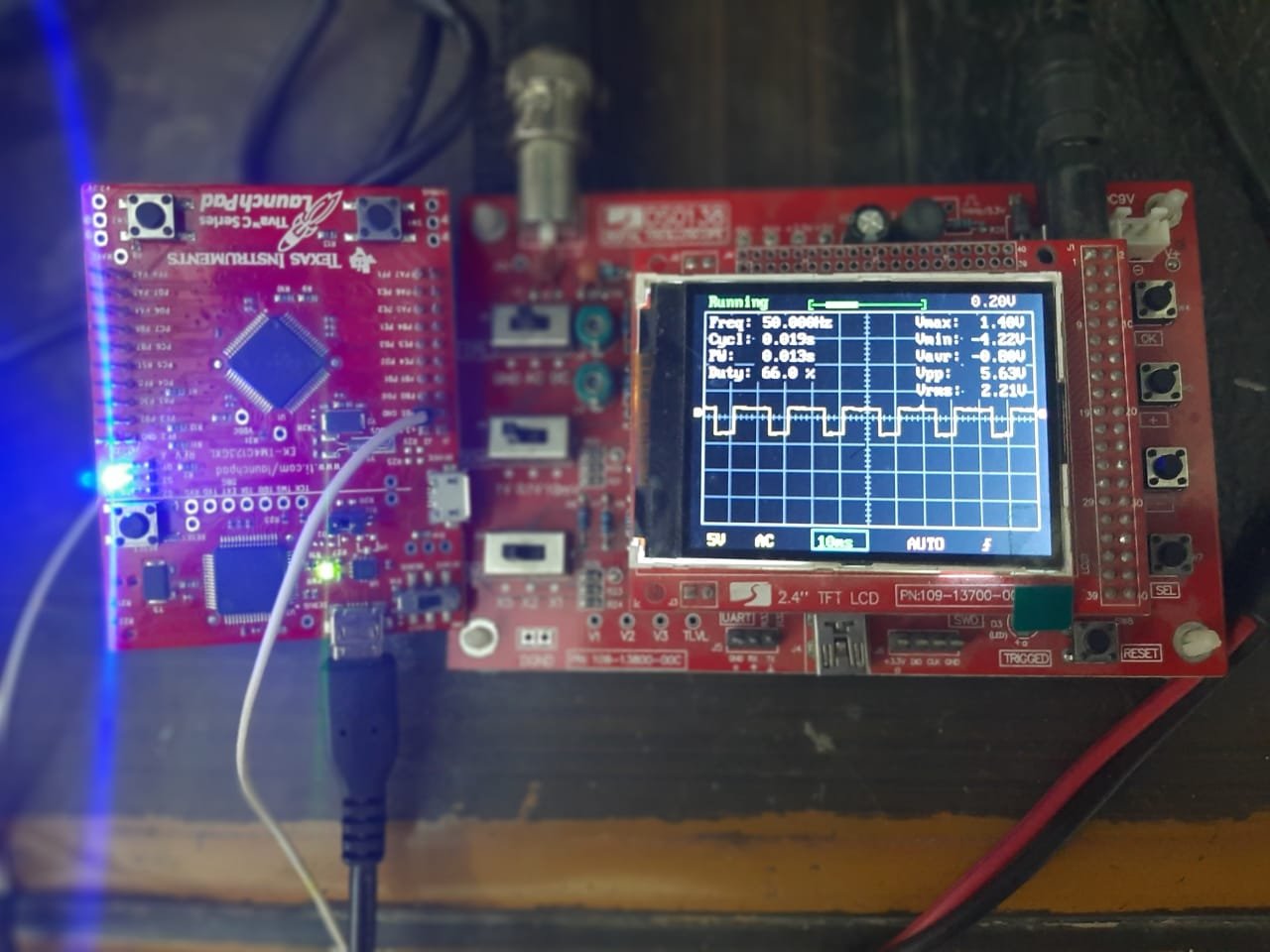
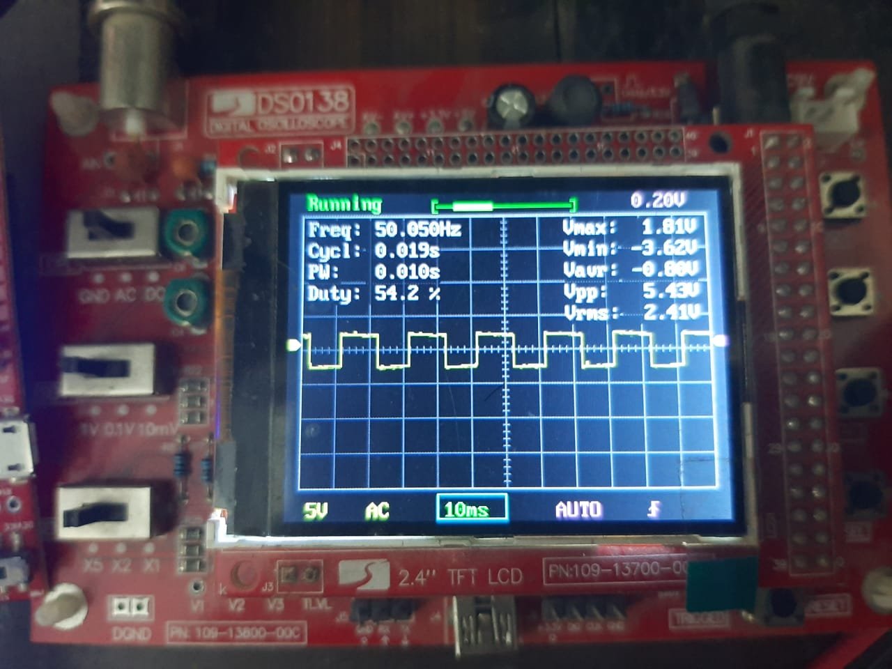
}Now create a new project using Keil uvision and upload this code to TM4C123G Tiva C Launchpad. After that press the reset button of the launchpad. You will 10KHz PWM signal on PF2 pin through an oscilloscope.
Keil uvision v5 Instructions
Note: If you are using Keil uvision v5, you should remove the void
SystemInit(void) function from the above code. Because the startup file in Keil v5 already contains the function SystemInit().
After that follow these steps to build above code with Keil uvision 5:
The other issue with the SystemInit() function in the new system_TM4C123.c is that it configures the clock generation which results in a different system clock rate than the default 16 MHz frequency. But the above sample code works on the default 16 MHz system clock. Therefore, the above program creates timing issues with Keil v5. You may retain the default system clock rate in Keil v5, by the following steps:
- Expand the Project->Device to show system_TM4C123.c (startup)
- Double click to open the file in the editor window
- Find the line “#define CLOCK_SETUP 1” as the figure below
- Comment out the line
- Rebuild the project

Conclusion
In conclusion, this tutorial provides a comprehensive guide on generating Pulse Width Modulation (PWM) using the TM4C123 microcontroller. By utilizing the PWM module of the TM4C123GH6PM, we have demonstrated how to create a square wave with variable frequency and duty cycle, showcasing the versatility of this microcontroller in controlling various applications. The use of the TM4C123 Tiva Launchpad in this tutorial makes it easy to follow along and implement PWM in real-world projects. Whether you’re controlling motors, LEDs, or other peripherals, the TM4C123 series offers a reliable solution for precise signal modulation.
Related TM4C123 Tiva Launchpad Tutorials:
- TM4C123 Timer as a Counter in Input-Edge Count Mode
- Frequency Measurement using TM4C123 Timers in Input-Edge Capture Mode
- Timer Interrupt TM4C123
- GPIO Interrupts TM4C123 Tiva Launchpad
- ADC TM4C123G Tiva C Launchpad
- Systick Timer Interrupt Programming TM4C123 ARM Cortex M4
Other PWM Tutorials:
Sir how to see output ot this code
Connect an oscilloscope to PF2 pin.
Running the code is going to HardFault.
No, it’s not. We got a perfect PWM output as shown in the video given at the end of the article.
Sir i am unable to generate the same signal using any other generator except generator 3. kindly guide me regarding the address changing for using another generator.
Hi,
Please share your code here so that we can point out your mistakes.
I am using code compiler studio for this purpose and used library and changed varbiable names only.I am unable to get output on PD0 as it is designated for Mode 1 GEN 0. Here is the code:
#include “TM4C123GH6PM.h”
int a=1;
int main(void)
{
void Delay_ms(int n);
int duty_cycle = 4999;
/* Clock setting for PWM and GPIO PORT */
SYSCTL_RCGCPWM_R |= 2; /* Enable clock to PWM1 module */
SYSCTL_RCGCGPIO_R |= 0x08; /* Enable system clock to PORTD *
SYSCTL_RCC_R |= (1<<20); /* Enable System Clock Divisor function */
SYSCTL_RCC_R |= 0x000E0000; /* Use pre-divider valur of 64 and after that feed clock to PWM1 module*/
GPIO_PORTD_AFSEL_R &= 0x09; // not alternative /* PD0 sets a alternate function */
GPIO_PORTD_PCTL_R &= ~0x0000000F; /*set PD0 as output pin */
GPIO_PORTD_PCTL_R |= 0x00000005; /* make PD0 PWM output pin */
GPIO_PORTD_DEN_R |= (1<<2); /* set PD0 as a digital pin */
PWM1_0_CTL_R &= ~(1<<0); /* Disable Generator 0 counter */
PWM1_0_CTL_R &= ~(1<<1); /* select down count mode of counter 3*/
PWM1_0_GENA_R = 0x0000008C; /* Set PWM outpu1 when counter reloaded and clear when matches PWMCMPA */
PWM1_0_LOAD_R = 5000; /* set load value for 50Hz 16MHz/65 = 250kHz and (250KHz/5000) */
PWM1_0_CMPA_R = 4999; /* set duty cyle to to minumum value*/
PWM1_0_CTL_R = 1; /* Enable Generator 0 counter */
PWM1_ENABLE_R = 0x01; /* Enable PWM1 channel 0 output */
while(1)
{
duty_cycle = duty_cycle – 20;
if(duty_cycle <=0 )
duty_cycle =5000;
PWM1_0_CMPA_R = duty_cycle;
Delay_ms(10);
}
}
void Delay_ms(int time_ms)
{
int i, j;
for(i = 0 ; i < time_ms; i++)
for(j = 0; j < 3180; j++)
{} /* excute NOP for 1ms */
}
I don’t have the micro-controller board with me, so I want to use the logic analyzer of keil to view the pwm waveform. But I am getting what I should type in the logic analyzer. I tried guessing some port names but it didn’t work. Pls help me with this
We haven’t tried with logic analyzer.
Hello i havr very serious doubt , in Stm32 I have mostly seen ppl generate PWM through timers , however in case of TIVA we make use of PWM generators as u have done above , my question is why cant we do the same way in Stm32 like you have done .
Regards
Hi,
What will be clock speed without commenting
#define CLOCK_SETUP 1 .
Thanks you,
Ravi
May I please get a clean hard copy of this excellent presentation ? Right click and print doesn’t cut it as the ads clip much of the text and illustrations. I travel a lot and there isn’t always internet. Thank you so much for sharing.
Hello,
I have a problem with this code.
If I just flash it and press the button on the board, nothing happens.
If i start debugging though, place a breakpoint on line where the generator 3 counter is disabled ( PWM1->_3_CTL &= ~(1<<0); ), step over a couple of lines and then continue with run, then it works and I see the blue LED working as expected.
But it only works during debugging and with a breakpoint on this line.
Any idea what the problem might be and how to make it work during normal operation?
Thanks a lot for the amazing tutorials!
Kind regards,
Theo