In this user guide, we will look at an interesting way to use Radio Frequency Identification (RFID) technology via RFID reader module. These RFID reader modules are very handy in today’s fast-paced world. Due to their fast, accurate and secure nature, they are widely used with microcontrollers in various fields e.g. from supermarkets for fast checkouts to well-maintained security systems for banks/jails/server rooms. The RFID reader module that we will look upon is known as RC522. We will use Arduino UNO with it and show you some simple example sketches that will demonstrate how to use the reader module. Additionally, after looking through the example sketches we will also build our own door security system with the help of the RC522 RFID reader module.
By the end of this tutorial you will be able to:
- know the introduction about RC522 RFID reader module (features and pinout)
- interface the RC522 reader module with Arduino UNO
- read the RFID tag
- write data to RFID tag
- Build a door security system using RFID RC522 reader module
Recommended Components
The following components are used in this project or are helpful for building it with the Arduino.
| Component | How it’s used in this project | Buy on Amazon |
|---|---|---|
| Arduino Uno R3 | The main controller board that communicates with the RC522 reader over SPI and processes the scanned RFID data. | Check Price |
| Breadboard | Solderless board to build and prototype the circuit without soldering. | Check Price |
| Jumper Wires | Used to wire the RC522 SPI pins to the Arduino and make the other connections. | Check Price |
| RC522 RFID reader | Reads the RFID tags/cards over SPI and sends their UID to the Arduino. | Check Price |
As an Amazon Associate we earn from qualifying purchases. Prices and availability are accurate as of the date/time indicated and are subject to change.
RC522 RFID Reader Module
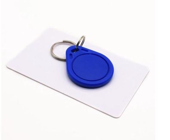
RC522 is a Multi-communication RFID Module for Arduino and Microcontrollers. The RC522 is known as MFRC-522 due to its NFX semiconductor microcontroller. The module allows the developers to interface it with any other SPI, I2C, and UART based microcontrollers. It comes with an RFID card tag and key fob consisting of 1KB of memory.
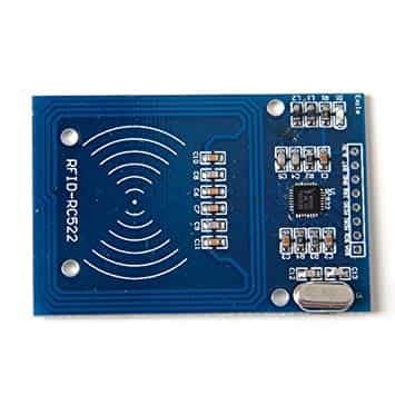
The RC522 module works on a 13.56 MHz frequency and it can act as a reader and write for UID/RFID cards. The RFID cards communicate with the module at a short distance with radio frequency due to the mutual induction technique. In most of the security and commercial products, the module is effective because the errors and issues with RFID Tags are detectable by it.
RFID Card Tag 1KB Memory Layout
The RFID card is a memory storage device having 1KB worth of memory. This memory is divided into 16 sectors (0-15) where each sector is further divided into 4 blocks (0,1,2,3). Each block is of 16 bytes. Thus 4 blocks x 16 bytes x 16 sectors = 1024 bytes which is 1KB.
RC522 RFID Reader Features
- RFID RC522 uses mutual induction to activate the cards and 13.56MHz for data transfer.
- The RFID Cards are useable from both sides of the module at a max of 5cm.
- Only 3.3V is required to activate the device.
- Its auto-sleep mode makes it less power consumption module.
- The module has three kinds of communications (UART, SPI, and I2C). Therefore, it is useable with almost every microcontroller or device in the market.
- The RFID cards and reader (RC522) can transfer data up to 10Mb/s.
RC522 RFID Module Applications
- RFID has most of the usage as a security device.
- In some companies, the devices use with shopping items.
- Some airports have also started using RFID to identify and keep track of bags and other items.
- The attendance or Parking system also uses RFID to keep the system secure.
Pinout
In this module, there are only two kinds of pins. So, the first one is power and the second one is the communication pins. Therefore, the device may have its microcontroller chip on itself but it only makes it to works as an RFID. The onboard microcontroller won’t make the module a stand-alone device.
All the pins of MFRC/RC522 RFID card Reader are:
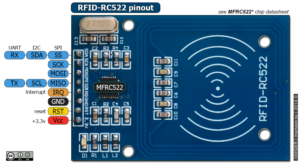
The table below shows the eight pins found on the RC522 RFID module. You can also view their descriptions.
| Pin | Description |
|---|---|
| VCC | The power pins are VCC. In some versions of RC522, this pin is denoted by 3V3 on the module instead of VCC. |
| RST | This is the reset pin for the module. Therefore, it resets the device in case of an error when a device isn’t giving any response. |
| GND | Ground helps to make the common ground with every external device, e.g. power Supply, Microcontroller or Arduino. |
| IRQ | The device can go into sleep mode to save power. So, the IRQ helps to wake it. |
| MISO | This pin connects with the Arduino/Microcontrollers for SPI communication. However, it transfers the data from module to Arduino. The MISO pin is also useable for other functions instead of SPI. It can also interface with I2C for clock pulse and UART Serial for Data transfer from the module. |
| MOSI | MOSI is the data input pin for RFID module in SPI communication |
| SCK | The SCK pins help to send the clock pulse in SPI communications. |
| SS | The SS pin is a chip enable pin in SPI communication. Therefore, it receives the signal when Master (Arduino) must perform SPI communication. The SS pin in RFID is useable as a second pin (SDA) for I2C communication. It also receives data during UART communication. |
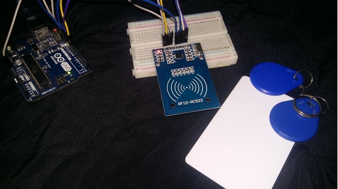
Interfacing the RC522 RFID reader module with Arduino UNO
As we have seen above, the RC522 module has 8 terminals which we will connect with the Arduino UNO. As the RC522 requires an operating voltage in the range of 2.5-3.3V hence the VCC terminal of the RC522 module will in common with the 3.3V pin of the Arduino UNO. Likewise, both the devices will have their grounds in common.
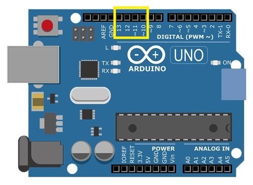
The SPI communication helps to communicate with RFID reader module, which is common in every microcontroller. Thus, we will use the SPI interface of Arduino UNO. Below you can view the SPI pins of Arduino UNO.
The table below shows the connections between the two devices that we will use in our project.
| RC522 RFID Reader Module | Arduino UNO |
|---|---|
| VCC | 3V3 |
| RST | Pin 9 |
| GND | GND |
| IRQ | Not connected |
| MISO | Pin 12 |
| MOSI | Pin 11 |
| SCK | Pin 13 |
| SDA | Pin 10 |
Components Required
We will need the following components to connect our Arduino UNO board with the RC522 module.
- Arduino UNO
- RC522 RFID Reader module
Follow the schematic diagram below and connect them accordingly.
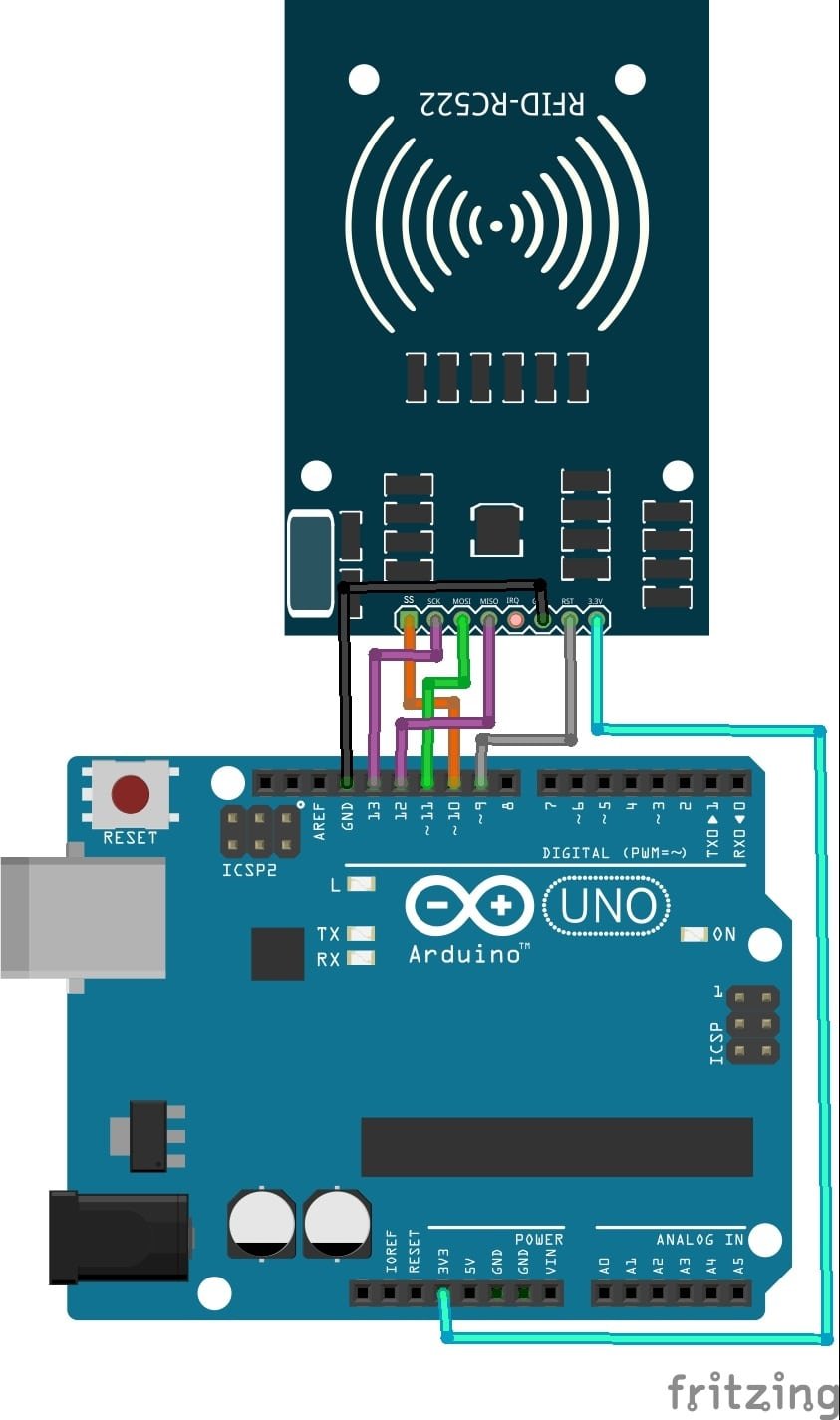
All the connections between the two devices are the same as we listed them in the table above.
Installing RC522 Library in Arduino IDE
We will use Arduino IDE to program our Arduino UNO. Thus, you should have the latest version of Arduino IDE.
To make it easier to use the RC522 RFID reader module, we have to install the MFRC522 library. With the help of this library we will be easily able to read/ write data to the RFID tag. Follow the steps below to successfully install it successfully.
We will use GitHub to download the library and then place them in the library folder of our Arduino IDE.
Click RFID Library to open the respective GitHub page for the library.
The webpage when you open the link will look something like this.
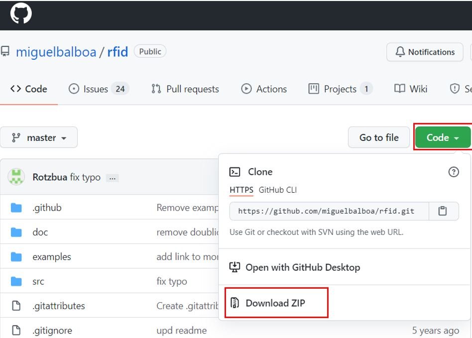
Click the Code button and go to the Download Zip option as highlighted in the figure. Your zip file will get downloaded to your computer right away. Now go to Sketch > Include Library > Add .zip Library inside the IDE to add the library.
Arduino Sketch: Reading RFID Tag
Now after assembling the RC522 RFID reader module and the Arduino UNO board together, let us proceed with an example sketch from the MFRC522 library to read the RFID tag.
Open your Arduino IDE and go to File > Examples > MFRC522 > DumpInfo. The following program code will open. This example sketch will display information about your RFID tag.
/*
 * --------------------------------------------------------------------------------------------------------------------
 * Example sketch/program showing how to read data from a PICC to serial.
 * --------------------------------------------------------------------------------------------------------------------
 * This is a MFRC522 library example; for further details and other examples see: https://github.com/miguelbalboa/rfid
 *
 * Example sketch/program showing how to read data from a PICC (that is: a RFID Tag or Card) using a MFRC522 based RFID
 * Reader on the Arduino SPI interface.
 *
 * When the Arduino and the MFRC522 module are connected (see the pin layout below), load this sketch into Arduino IDE
 * then verify/compile and upload it. To see the output: use Tools, Serial Monitor of the IDE (hit Ctrl+Shft+M). When
 * you present a PICC (that is: a RFID Tag or Card) at reading distance of the MFRC522 Reader/PCD, the serial output
 * will show the ID/UID, type and any data blocks it can read. Note: you may see "Timeout in communication" messages
 * when removing the PICC from reading distance too early.
 *
 * If your reader supports it, this sketch/program will read all the PICCs presented (that is: multiple tag reading).
 * So if you stack two or more PICCs on top of each other and present them to the reader, it will first output all
 * details of the first and then the next PICC. Note that this may take some time as all data blocks are dumped, so
 * keep the PICCs at reading distance until complete.
 *
 * @license Released into the public domain.
 *
 * Typical pin layout used:
 * -----------------------------------------------------------------------------------------
 *             MFRC522      Arduino       Arduino   Arduino    Arduino          Arduino
 *             Reader/PCD   Uno/101       Mega      Nano v3    Leonardo/Micro   Pro Micro
 * Signal      Pin          Pin           Pin       Pin        Pin              Pin
 * -----------------------------------------------------------------------------------------
 * RST/Reset   RST          9             5         D9         RESET/ICSP-5     RST
 * SPI SS      SDA(SS)      10            53        D10        10               10
 * SPI MOSI    MOSI         11 / ICSP-4   51        D11        ICSP-4           16
 * SPI MISO    MISO         12 / ICSP-1   50        D12        ICSP-1           14
 * SPI SCK     SCK          13 / ICSP-3   52        D13        ICSP-3           15
 *
 * More pin layouts for other boards can be found here: https://github.com/miguelbalboa/rfid#pin-layout
 */

#include <SPI.h>
#include <MFRC522.h>

#define RST_PIN         9          // Configurable, see typical pin layout above
#define SS_PIN          10         // Configurable, see typical pin layout above

MFRC522 mfrc522(SS_PIN, RST_PIN);  // Create MFRC522 instance

void setup() {
	Serial.begin(9600);		// Initialize serial communications with the PC
	while (!Serial);		// Do nothing if no serial port is opened (added for Arduinos based on ATMEGA32U4)
	SPI.begin();			// Init SPI bus
	mfrc522.PCD_Init();		// Init MFRC522
	delay(4);				// Optional delay. Some board do need more time after init to be ready, see Readme
	mfrc522.PCD_DumpVersionToSerial();	// Show details of PCD - MFRC522 Card Reader details
	Serial.println(F("Scan PICC to see UID, SAK, type, and data blocks..."));
}

void loop() {
	// Reset the loop if no new card present on the sensor/reader. This saves the entire process when idle.
	if ( ! mfrc522.PICC_IsNewCardPresent()) {
		return;
	}

	// Select one of the cards
	if ( ! mfrc522.PICC_ReadCardSerial()) {
		return;
	}

	// Dump debug info about the card; PICC_HaltA() is automatically called
	mfrc522.PICC_DumpToSerial(&(mfrc522.uid));
}
Make sure the RST pin is correctly defined in the sketch according to your connections.
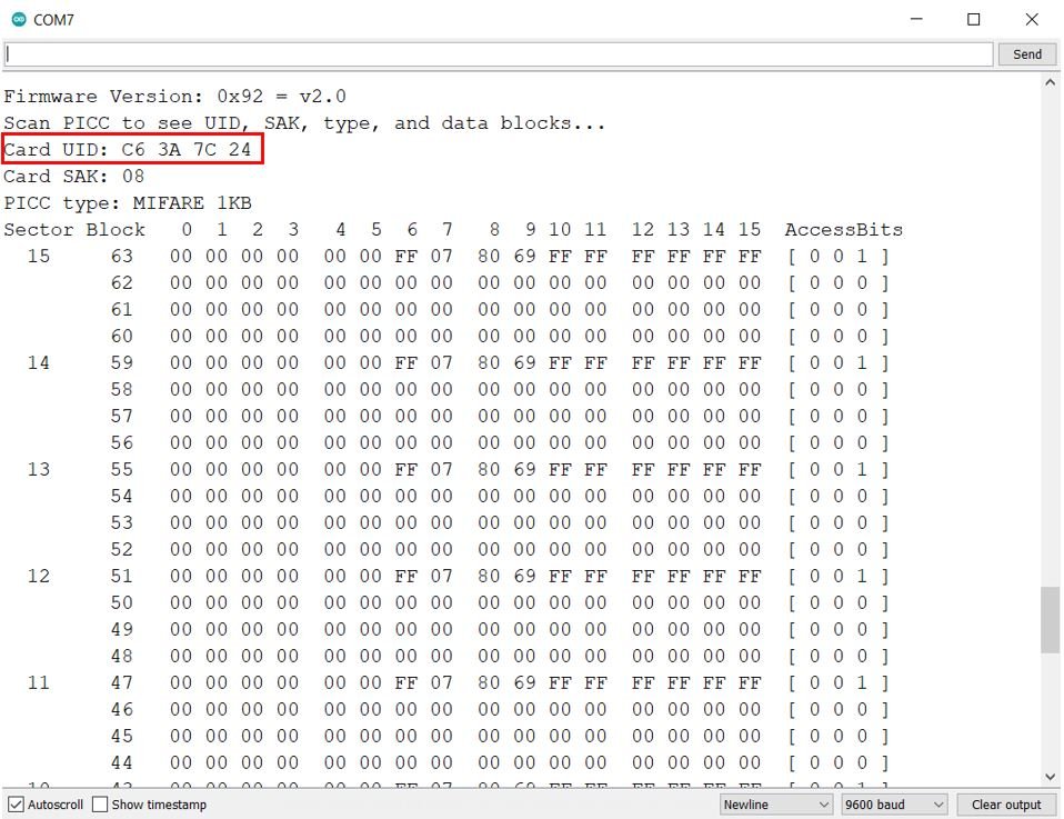
To see the demonstration of the above code, upload the code to Arduino. But, before uploading code, make sure to select the Arduino board from Tools > Board and also select the correct COM port to which the Arduino board is connected from Tools > Port.

Once the code is uploaded to Arduino, bring the RFID tag closer to it. Open your serial monitor and set its baud rate to 9600. Instantly, your serial monitor will display information regarding your tag. This includes the UID which is the unique ID of the tag and its size.
Arduino Sketch: Writing data to an RFID tag
Open your Arduino IDE and go to File > New to open a new file. Copy the code given below in that file.
This sketch writes “Welcome!” to our RFID tag.
#include <SPI.h>
#include <MFRC522.h>

#define SS_PIN 10
#define RST_PIN 9

MFRC522 mfrc522(SS_PIN, RST_PIN);
MFRC522::MIFARE_Key key;

int block=1;

byte data[16] = {"Welcome!"};
byte read_data[18];

void setup()
{
    Serial.begin(115200);
    SPI.begin();
    mfrc522.PCD_Init();
    Serial.println("Scanning...");

  for (byte i = 0; i < 6; i++) {
    key.keyByte[i] = 0xFF;
  }
}

void loop()
{

  if ( ! mfrc522.PICC_IsNewCardPresent()) {
    return;
  }


  if ( ! mfrc522.PICC_ReadCardSerial())
  {
    return;
  }
    Serial.println("Card is selected successfully!");

   writeBlock(block, data);
   readBlock(block, read_data);

   Serial.print("Reading block ");
   for (int j=0 ; j<16 ; j++)
   {
     Serial.write (read_data[j]);
   }
   Serial.println("");
}

int writeBlock(int blockNumber, byte arrayAddress[])
{
  int largestModulo4Number=blockNumber/4*4;
  int trailerBlock=largestModulo4Number+3;
  if (blockNumber > 2 && (blockNumber+1)%4 == 0){Serial.print(blockNumber);
  Serial.println(" is a trailer block");
  return 2;}
  Serial.print(blockNumber);
  Serial.println(" is a data block");


  byte status = mfrc522.PCD_Authenticate(MFRC522::PICC_CMD_MF_AUTH_KEY_A, trailerBlock, &key, &(mfrc522.uid));
  if (status != MFRC522::STATUS_OK) {
         Serial.print("PCD_Authenticate() failed: ");
         Serial.println(mfrc522.GetStatusCodeName(status));
         return 3;
  }

  status = mfrc522.MIFARE_Write(blockNumber, arrayAddress, 16);
  if (status != MFRC522::STATUS_OK) {
           Serial.print("MIFARE_Write() failed: ");
           Serial.println(mfrc522.GetStatusCodeName(status));
           return 4;
  }
  Serial.println("Block has been written!");
}


int readBlock(int blockNumber, byte arrayAddress[])
{
  int largestModulo4Number=blockNumber/4*4;
  int trailerBlock=largestModulo4Number+3;

  byte status = mfrc522.PCD_Authenticate(MFRC522::PICC_CMD_MF_AUTH_KEY_A, trailerBlock, &key, &(mfrc522.uid));

  if (status != MFRC522::STATUS_OK) {
         Serial.print("PCD_Authenticate() failed (read): ");
         Serial.println(mfrc522.GetStatusCodeName(status));
         return 3;
  }

byte buffersize = 18;
status = mfrc522.MIFARE_Read(blockNumber, arrayAddress, &buffersize);
  if (status != MFRC522::STATUS_OK) {
          Serial.print("MIFARE_read() failed: ");
          Serial.println(mfrc522.GetStatusCodeName(status));
          return 4;
  }
  Serial.println("Block read successfully!");
}
How the Code Works?
Including Libraries
Firstly, we will include the necessary libraries required for this project. The MFRC522 library helps to decode and encode the incoming data from the RFID module and SPI helps to establish the SPI communication. These two libraries are dependent on each other.
#include <SPI.h>
#include <MFRC522.h>
Secondly, we will specify the SS pin and RST pin connection with the Arduino UNO. It is pin 10 and pin 9 respectively.
#define SS_PIN 10
#define RST_PIN 9
Next, we will create an instance of MFRC522 and pass the SS pin and the RST pin as parameters. Additionally, we will also create a MIFARE_Key structure called ‘key.’ This will be used later on to save the data on the RFID card.
MFRC522 mfrc522(SS_PIN, RST_PIN);
MFRC522::MIFARE_Key key;
Now we will define the block where we will store the data. It can take the value of 0,1 or 2. As block 3 is the trailer block thus we do not use it. In our case, we have selected block 1 to store our data.
int block=1; Then we will create an array called ‘data.’ This will hold 16 bytes of data message that we will store on the card. You can add any text.
We will also have to define another array of 18 bytes to read the data that we stored in our card. This array is named as ‘read_data.’
byte data[16] = {"Welcome!"};
byte read_data[18];
setup()
Inside the setup() function, the serial connection is opened at a baud rate of 9600.
Serial.begin(115200);Now we will describe the SPI initialization and Module initialization which needs to be done by the following lines of code.
 SPI.begin();
 mfrc522.PCD_Init();
Now we will use a for loop for the security key to use the write/read functions of the library. In our case all 6 key bytes are set to the default 0xFF.
Serial.println("Scanning...");

  for (byte i = 0; i < 6; i++) {
    key.keyByte[i] = 0xFF;
  }
loop()
Inside the infinite loop() function we will first detect the card and then write our data on its memory.
if ( ! mfrc522.PICC_IsNewCardPresent()) {
    return;
  }

  if ( ! mfrc522.PICC_ReadCardSerial())
  {
    return;
  }
    Serial.println("Card is selected successfully!");
Through the writeBlock() function, we will pass two parameters inside it. The first is the block number and the second is the data that we want to write on the specific block.
writeBlock(block, data);
Likewise we will read the data using the readBlock() function. This function also takes in two parameters. The first is the block number and the second is the read_data array respectively.
readBlock(block, read_data);First, we will write the data on to our block and then we will read it to see whether it was written properly or not. The following lines of code will print the data that we wrote on the block by displaying the read_data() array on the serial monitor. This will be achieved by using a for loop.
Serial.print("Reading block ");
   for (int j=0 ; j<16 ; j++)
   {
     Serial.write (read_data[j]);
   }
   Serial.println("");
Demonstration
To see the demonstration of the above code, upload the code to Arduino. But, before uploading code, make sure to select the Arduino board from Tools > Board and also select the correct COM port to which the Arduino board is connected from Tools > Port.
Once the code is uploaded to Arduino, bring the RFID tag closer to it. Open your serial monitor and set its baud rate to 115200. Instantly, your serial monitor will display different messages.

Door Lock Security System using RFID reader module
Now after learning how to write and read to the RFID card let us proceed further and build our door lock security system. A door Security System will be used to stop unauthorized people to get access to a room or a building. We will use our RFID card and RC522 reader module with our programmed Arduino UNO. Additionally, we will use a 0.96 SSD1306 OLED display to show the different messages to the user.

Installing OLED Libraries in Arduino IDE
To use the OLED display in our project, we have to install the Adafruit SSD1306 library and Adafruit GFX library in Arduino IDE. Follow the steps below to install them successfully.
Open Arduino IDE and click on Sketch > Library > Manage Libraries. Type ‘SSD1306’ in the search tab and install the Adafruit SSD1306 OLED library.

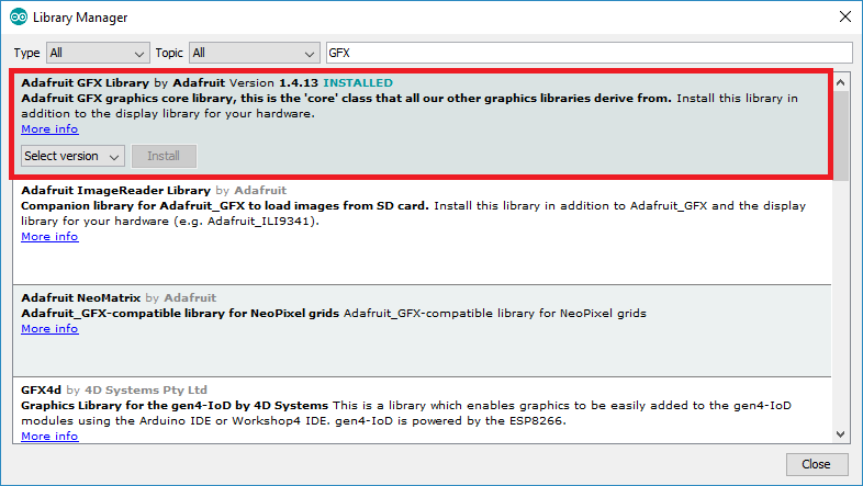
We will also require the Adafruit GFX library which is a dependency for SSD1306. Type ‘Adafruit GFX’ in the search tab and install it as well.
After installing the libraries, restart your IDE.
Arduino I2C Pins
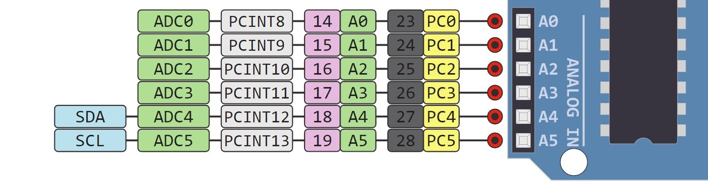
To interface OLED with Arduino, we need to use I2C pins of Arduino which are A4 (SDA) and A5 (SCL) pins. The I2C pins stated above are set in default. If we want to change the GPIO pins we have to set them in code. The diagrams below show the I2C pins of Arduino marked with different color rectangles.
Note: If we use other GPIO pins of Arduino for I2C communication, we can define other pins inside our Arduino sketch. We don’t have to use default I2C pins.
Connection Diagram– OLED with Arduino and RC522 Module
Required Components:
- Arduino UNO
- RC522 RFID reader module
- RFID card
- OLED display
- Connecting Wires
- Breadboard
Assemble the circuit as shown in the schematic diagram below:

As you can see above, we have connected all the VCC terminals with a 3.3V pin of Arduino. The SCL terminal of the OLED is connected with A5 and the SDA terminal of the OLED is connected with the A4 pin of Arduino. The grounds of all three devices are common. The connections of RC522 module has already been discussed before and we are using the default SPI pins of that.
Arduino Sketch: Door Lock Security System
Open your Arduino IDE and go to File > New. A new file will open. Copy the code given below in that file and save it. You will have to specify your unique tag ID.
#include <SPI.h>
#include <MFRC522.h>
#include <Wire.h>
#include <Adafruit_GFX.h>
#include <Adafruit_SSD1306.h>

#define RST_PIN 9
#define SS_PIN 10

byte readCard[4];
String My_ID = "********";
String ID = "";

MFRC522 mfrc522(SS_PIN, RST_PIN);
Adafruit_SSD1306 display = Adafruit_SSD1306(128, 64, &Wire, -1);

void setup()
{
  SPI.begin();
  mfrc522.PCD_Init();
  display.begin(SSD1306_SWITCHCAPVCC, 0x3C);

  display.clearDisplay();
  display.setTextColor(WHITE);
  display.setCursor(0,0);
  display.setTextSize(1);
  display.print("Scan Your Card...");
  display.display();
}

void loop()
{
  while (getID())
  {
    display.clearDisplay();
    display.setCursor(0,0);
    display.setTextSize(1);

    if (ID == My_ID)
    {

     display.print("ACCESS GRANTED!");

    }
    else
    {
      display.print("ACCESS DENIED!");
    }

      display.display();
      display.setCursor(0, 10);
      display.print(" ID : ");
      display.print(ID);
      display.display();

    delay(2000);

    display.clearDisplay();
    display.print(" Access Control ");
    display.setCursor(0, 10);
    display.print("Scan Your Card...");
    display.display();
  }
}

boolean getID()
{
  if ( ! mfrc522.PICC_IsNewCardPresent()) {
  return false;
  }
  if ( ! mfrc522.PICC_ReadCardSerial()) {
  return false;
  }
  ID = "";
  for ( uint8_t i = 0; i < 4; i++) {
  //readCard[i] = mfrc522.uid.uidByte[i];
  ID.concat(String(mfrc522.uid.uidByte[i], HEX));
  }
  ID.toUpperCase();
  mfrc522.PICC_HaltA();
  return true;
}
How the Code Works?
Including Libraries and defining parameters
Firstly, we will include all the following libraries which are required for this project. SPI.h will be used for SPI communication protocol between Arduino and RC522 module. Wire.h will allow us to communicate through the I2C protocol between the Arduino and the OLED. Whereas the other libraries are the ones which we previously installed and are required for the proper functionality of the OLED display and the RC522 module.
#include <SPI.h>
#include <MFRC522.h>
#include <Wire.h>
#include <Adafruit_GFX.h>
#include <Adafruit_SSD1306.h>
In the following lines we will define the RST and SS pins and create an instance of MFRC522 called mfrc522() and pass the pins defined earlier as the two parameters inside it. Additionally, we will also create a string variable to hold our unique tag ID. This is named as ‘My_ID.’
#define RST_PIN 9
#define SS_PIN 10

byte readCard[4];
String My_ID = "********";
String ID = "";

MFRC522 mfrc522(SS_PIN, RST_PIN);
Next, we will initialize the OLED display by creating an object and specifying the width, height, I2C instance (&Wire), and -1 as parameters inside Adafruit_SSD1306. -1 specifies that the OLED display which we are using does not have a RESET pin. If you are using the RESET pin then specify the GPIO through which you are connecting it with your development board.
Adafruit_SSD1306 display = Adafruit_SSD1306(128, 64, &Wire, -1);
setup()
Inside the setup() function, we will initialize the SPI protocol, the MC522 module, and the OLED display.
SPI.begin();
mfrc522.PCD_Init();
display.begin(SSD1306_SWITCHCAPVCC, 0x3C);
Then we will display the ‘Scan Your Card…’ message on the display.
 display.clearDisplay();
  display.setTextColor(WHITE);
  display.setCursor(0,0);
  display.setTextSize(1);
  display.print("Scan Your Card...");
  display.display();
loop()
Inside the infinite loop() function we will first detect the card and then check if its ID matches the ID that we stored in the variable ‘MY_ID.’ If it does then the OLED display shows “ACCESS GRANTED!” otherwise it shows “ACCESS DENIED!” and the process continues after a delay of 2 seconds.
while (getID())
  {
    display.clearDisplay();
    display.setCursor(0,0);
    display.setTextSize(1);

    if (ID == My_ID)
    {

     display.print("ACCESS GRANTED!");

    }
    else
    {
      display.print("ACCESS DENIED!");
    }

      display.display();
      display.setCursor(0, 10);
      display.print(" ID : ");
      display.print(ID);
      display.display();

    delay(2000);

    display.clearDisplay();
    display.print(" Access Control ");
    display.setCursor(0, 10);
    display.print("Scan Your Card...");
    display.display();
  }
Demonstration
To see the demonstration of the above code, upload the code to Arduino. But, before uploading code, make sure to select the Arduino board from Tools > Board and also select the correct COM port to which the Arduino board is connected from Tools > Port.
Once the code is uploaded to your Arduino, the OLED will display “Scan Your Card…” Bring your card whose ID you used in the sketch, closer to the RC522 module. Instantly, the OLED will display “ACCESS GRANTED!” Now bring another card closer to the module. Now the OLED will display “ACCESS DENIED!”
Watch the video below:
This way we have created a door lock security system.
For more RFID tutorials follow the links below: