The electromechanical relays, as the name suggests, are powered electrically whereas their operation is mechanical. They are used as switches for the isolation of circuits or fault detection in transmission lines and for many other purposes. A high powered circuit can also be controlled by them by providing a low power signal.
Electromechanical Relays CONSTRUCTION
The simple relays have a wire or a coil wrapped around a magnetic core, an armature and a set of moving contacts. A magnetic field is generated as soon as the current passes through the coil. The armature is activated by this magnetic field which moves the contacts and opens or closes a connection.
The diagram illustrates the different parts in a relay and how a relay is operated. On the left side of the figure, a relay is shown in an ‘off’ state. The contacts are stationary and no movement takes place. The right side of the figure shows a relay in the ‘on’ state. The coil is energized and the contacts start moving to open or close a switch. Relays working is very important to understand before using them in projects.
TYPES OF ELECTROMECHANICAL RELAYS
GENERAL PURPOSE RELAYS
General purpose relays can have different number of poles ranging from one pole to eight poles. They can also be either single throw or double throw. These relays are rated on the basis of the current handling capability of the of its switch contacts.These are generally found in copy machines, computers, and other electronic equipments.
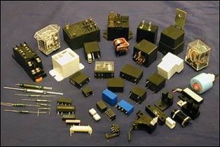
POWER RELAY
For higher values of currents and greater loads, power relay is used. It is commonly used for the current range of 10-50 A or more. It can be either single pole or double pole.
CONTACTOR
It is also a high power relay but it is mainly used for industrial applications to control high currents and voltages. That is why they always consist of double-make contacts.
TIME DELAY RELAY
After the energization of coil, it might take some time in opening or closing of the contacts. This is known as ‘delay-on-operate’. After the removal of power from the coil the contacts will not move from their actuated position. These timings can be adjusted accordingly by the relay itself or from an external circuit.
How to use relay in electronic circuit?
A typical circuit consists of an NPN transistor switch. The coil of the relay is driven by this switch. Zero or negative voltage on the base of transistor indicates that the transistor is off and no current is flowing. Hence the relay coil is also in a de-energized state.Now if a large amount of current is given at the base of the transistor, the current will from the base of the transistor to the emitter and a larger current will be flowing from the collector to the emitter through the NPN transistor.
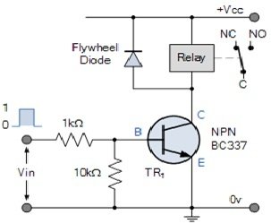
The relay coil is an inductor. The transistor switching action will produce a maximum current flow due to the coil’s DC resistance. The magnetic field of the relay coil stores some of this electrical energy in itself. The magnetic field diminishes as soon as the transistor is switched off because the current passing through the relay coil will start decreasing. But the stored energy in the magnetic field produces a reverse voltage across the coil. A high voltage spike is thus produced which can damage the transistor. A flywheel diode is connected to protect the trasnsistor from getting damaged by this high voltage. This diode dissipates the stored energy in the coil
RELAYS INTERFACING WITH MICROCONTROLLERS
The connection between a microcontroller and a relay must never be made directly. Microcontroller interfacing circuits are used for this purpose. A driver circuit should be used between them.
WHY??
There are two main reasons for it:
- As the relay has to move its contacts mechanically therefore a lot of current is required for the energizing of coil. The source or sink current of a pic microcontroller is just 25mA whereas an amount of 50 to 100mA current is required by a relay to function properly.
- Due to the presence of back emf, the negative voltages can reach the microcontroller and damage it.

Relay_Driver_Circuit_Using_Single_Transistor
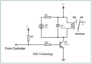
The above circuit is a relay driver circuit. The transistor used here is BC547. When a logic 0 is given to the port pin of transistor then the relay turns off and when a logic 1 is given to it, the relay turns on. A diode 1N4007 is connected to protect the components against the back emf. This back emf is generated in the coil of the relay when the transistor turns off. The LED indicates the state of the relay; whether it is on or off. A resistor R1 is connected which defines the intensity of the LED.
We will study the interfacing of relays with microcontroller in two ways:
- Through a transistor.
- By using ULN2003
RELAY INTERFACING WITH PIC16F877A THROUGH TRANSISTORS
The transistor acts as a switch. The amount of current needed for the relay operation is carried by this transistor. The transistor used here is BC547. This tranisitor gets turned on when the RB7 pin of the controller is at a high potential. Therefore the current starts flowing through the relay.
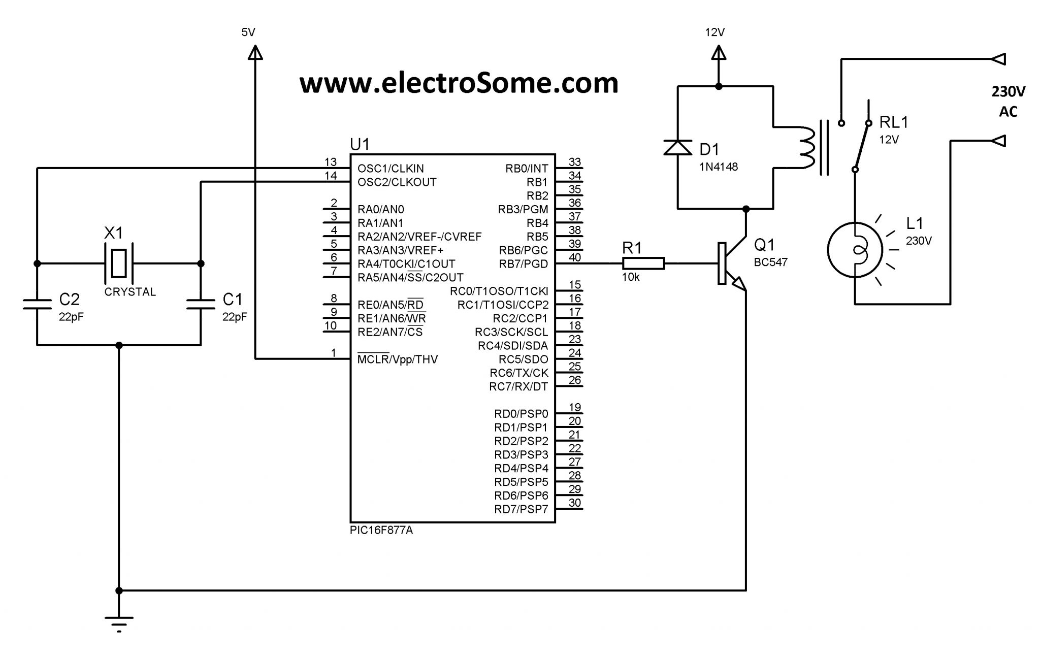

A freewheeling diode is also connected across the relay in this circuit. The purpose of this diode is to protect the microcontroller as well as the transistor from the back emf of the coil, otherwise it can damage them both. A fast switching diode 1N4148 has been used here. A DC voltage supply of 12V is given to the microcontrollers. Two capacitors each of 22 pF and a crystal is connected across the 13th and 14th pin of the microcontroller. The crystal provides clock to the microcontroller for its functioning.
This is a simple circuit which is just used to turn on a light bulb. The microcontroller is programmed, at a certain time under a certain condition; it will send a signal to the relay. The coil of relay will be energized and it will pull the contact towards it, thereby making a path for the current to flow which will result in the lighting up of the bulb.
RELAY INTERFACING WITH PIC16F77A THROUGH ULN2003
If more relays are to be connected in the circuit then the use of transistors will become difficult. In such a situation ULN2803 and ULN2003 can be used. Both these ICs have built in clamp diodes therefore there is no need of connecting freewheeling diodes.
ABOUT ULN2003:
It has 7 inputs and 7 outputs. The 8th pin is the ground pin.

The ULN2003 is known as a high voltage and current driver IC. It has seven darlington pairs. When two bipolar transistors form an arrangement, it is called as the darlington pair. This IC is also used in driving a number of loads and display drivers. Stepper motor is normally driven through this IC. A peak current of 600mA can be handled by the pair of darlington present in ULN2003.
The ULN2003 does not give any voltage on its output. If I high input is given to it then the corresponding output will be ground. The 9th pin ‘com’ is used in cases where it needs to drive a load which has recoil current like relays and motors etc.

As it can be seen from the above circuit diagram, a ULN2003 is connected between the microcontroller and relays in order to drive multiple relays. The input is taken from the microcontroller pins and the output corresponding to each input is given to the 5 relays on the output. In both the above circuits, the VDD pin of microcontroller should be connected to 5V DC and the VSS and GND should be given 0V. These circuits are very popular in electronics projects.
Photo Credits:
- through microcontroller and transistor interfacing by electrosome
- construction and working by globalspec
- transistor interfacing by electronics-tutorials
Wow keep it up !!!
I am satisfied with your notes
You have mentioned A DC voltage supply of 12V is given to the microcontrollers.