In this Arduino project, we will create a home automation system that will control home appliances using an Ethernet shield from a distance. The Ethernet shield will allow us to connect the Arduino to the internet to get instructions to switch appliances ON/OFF from a webpage. So in this ethernet based home automation project, we will be able to control home devices through a web server that can be accessed from the same network to which your PC or mobile browser is connected.
Recommended Components
The following components are used in this project or are helpful for building it with the Arduino.
| Component | How it’s used in this project | Buy on Amazon |
|---|---|---|
| Arduino Uno R3 | The main controller board that runs the project sketch and coordinates all the connected modules. | Check Price |
| Ethernet Shield | Connects the Arduino to your network so the appliances can be controlled from a web page. | Check Price |
| Relay Module | Switches the mains-powered appliances on and off using a 5V signal from the Arduino. | Check Price |
| Breadboard | Lets you prototype and wire the circuit without soldering. | Check Price |
| Jumper Wires | Used to make the connections between the Arduino, modules and breadboard. | Check Price |
As an Amazon Associate we earn from qualifying purchases. Prices and availability are accurate as of the date/time indicated and are subject to change.
Ethernet Based Home Automation System Overview
We will require the following components for this project.
Required Components:
- Arduino Uno: We will use Arduino Uno due to its compatibility with Ethernet shield.It also provides several digital pins to interface with the LCD and the relay module at the same time.
- 4 Channel Relay Modules: The module we will use in this project is HL-54S. It switches on and off using a 5V logic signal from Arduino. It can handle up to 250VAC and 10A. These modules have 4 relays so we can control 4 AC devices or appliances.
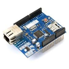
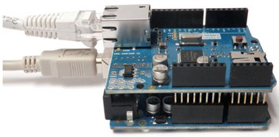
- Ethernet Shield: The Ethernet Shield connects your Arduino to the internet in less than a minute. Just plug this module onto your Arduino board, connect it to your network with an RJ45 cable. This module is open source, all its documents and schematics are available on the Arduino website.
- AC bulbs with holders: AC bulbs are used to represent devices and appliances. Because it is easy to handle and very useful when you are prototyping any AC project. In the final product, you can just replace it with an AC socket to control.
- AC wire with plug: Use good quality wire when working with higher voltages. It is always good to use electrical tape to cover connections.
- External 5 volt supply: 5-volt dc supply is required to switch the relay ON and OFF. Otherwise, it does not work. Also do not supply 5v from Arduino.
How does Ethernet Based Home Automation Work?
In this Ethernet based home automation system, Arduino Uno is used as the brain of our circuit.
You can view the operations constituting the Ethernet based home automation system in the block diagram below:
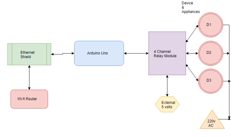
- Firstly the Ethernet shield connects with the Wi-Fi router and displays an IP address on the Arduino IDE Serial monitor.
- This IP address is the URL which is used to open the web page to control the appliances.

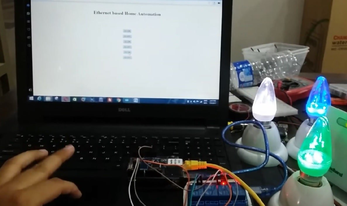
The web page consists of six buttons that will control the appliances. When we click a button the corresponding relay is switched ON or OFF accordingly. For demonstration purposes, we will use different colored light bulbs.
Connection Diagram of Ethernet Based Home Automation Project
In this section, we will explain the connections of the various components specified above with Arduino Uno to form the home automation system.
Let us discuss them one by one.
Arduino with Ethernet Shield
Ethernet Shield comes with different pins, provided for connections. We place this shield on the Arduino board properly and connect the Ethernet Port with the router providing the internet service. Note that The Ethernet shield is attached to pins 10, 11, 12, 13 so those cannot be used as general purpose input output pins.
Note: This shield is also compatible with Arduino Mega so you can also use that as well if you want to control more devices.
Connect the Ethernet shield with router as shown in the picture below:
Refer to the following article to get to know the mandatory requirements before plugging this shield on the Arduino board.
Arduino with Channel Relay modules
The relay module for Arduino is one of the most powerful applications for Arduino as it can be used to control both A.C and D.C devices by simply controlling the relay by giving 5V. A relay is basically a switch which is operated electrically by an electromagnet. A relay can be used to control high voltage electronic devices such as motors as well as low voltage electronic devices such as a light bulb or a fan.
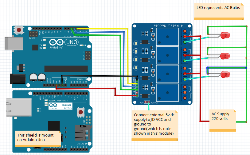
We will be using the 4 relay Arduino module in our home automation project.
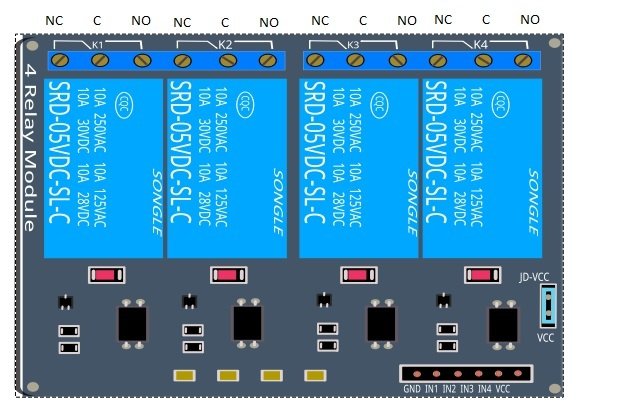
- External 5 volt to JD VCC.
- Ground to ground.
- IN1 to Pin 3.
- IN2 to Pin 4.
- IN3 to Pin5.
- VCC to Arduino 5V.
- Connect one end of all bulbs to the normally open terminal of relays.
- One end of 220VAC to all common terminals of relay and other ends with other terminals of the light lamps.
Ethernet Based Home Automation System Arduino Code
We will use Arduino IDE to program our Arduino board. Open your Arduino IDE and go to File > New to open a new file. Copy the code given below in that file and save it.
#include <SPI.h>
#include <Ethernet.h>

byte mac[] = {0xDE, 0xAD, 0xBE, 0xEF, 0xFE, 0xED};
EthernetServer server(80);

void setup() {
  pinMode(3, OUTPUT);
  pinMode(4, OUTPUT);
  pinMode(5, OUTPUT);
  digitalWrite(3 , HIGH);
  digitalWrite(4 , HIGH);
  digitalWrite(5 , HIGH);
  Ethernet.begin(mac);
  server.begin();
  Serial.begin(9600);
  Serial.println("Server address:");
  Serial.println(Ethernet.localIP());
}

void loop() {
  EthernetClient client = server.available();
  if (client) {
    boolean currentLineIsBlank = true;
    String buffer = "";
    while (client.connected()) {
      if (client.available()) {
        char c = client.read();
        buffer += c;
        if (c == '\n' && currentLineIsBlank) {
          client.println("HTTP/1.1 200 OK");
          client.println("Content-Type: text/html");
          client.println();
          client.print("<center><br><h1>Ethernet based Home Automation</h1><br><br><br><FORM>");
          client.print("<P> <INPUT type=\"submit\" name=\"status\" value=\"S1 ON\">");
          client.print("<P> <INPUT type=\"submit\" name=\"status\" value=\"S1 OFF\">");
          client.print("<P> <INPUT type=\"submit\" name=\"status\" value=\"S2 ON\">");
          client.print("<P> <INPUT type=\"submit\" name=\"status\" value=\"S2 OFF\">");
          client.print("<P> <INPUT type=\"submit\" name=\"status\" value=\"S3 ON\">");
          client.print("<P> <INPUT type=\"submit\" name=\"status\" value=\"S3 OFF\">");
          client.print("</FORM></center>");
          break;
        }
        if (c == '\n') {
          currentLineIsBlank = true;
          buffer = "";
        }
        else if (c == '\r') {
          if (buffer.indexOf("GET /?status=S1+ON") >= 0)
            digitalWrite(3, LOW);


          if (buffer.indexOf("GET /?status=S1+OFF") >= 0)
            digitalWrite(3, HIGH);


          if (buffer.indexOf("GET /?status=S2+ON") >= 0)
            digitalWrite(4, LOW);

          if (buffer.indexOf("GET /?status=S2+OFF") >= 0)
            digitalWrite(4, HIGH);


          if (buffer.indexOf("GET /?status=S3+ON") >= 0)
            digitalWrite(5, LOW);


          if (buffer.indexOf("GET /?status=S3+OFF") >= 0)
            digitalWrite(5, HIGH);

        }
        else {
          currentLineIsBlank = false;
        }
      }
    }
    client.stop();
  }
}
How the Code Works?
We will start by including the necessary libraries for this project. Both the required libraries are built-in so you will not be required to install them.
#include <SPI.h>
#include <Ethernet.h>
Next specify the MAC address of the shield:
byte mac[] = {0xDE, 0xAD, 0xBE, 0xEF, 0xFE, 0xED};The EthernetServer object will be used to set up the web server. We will pass the default HTTP port which is 80, as the input to the constructor. This will be the port where the server will listen to the requests.
EthernetServer server(80);setup()
Inside the setup() function, configure Arduino pins 3, 4 ,5 connected with IN1, IN2 and IN3 of the 4 Channel Relay Module. These pins will control the light bulbs. This is done by using the pinMode() function. Specify the pin as the first parameter and the mode as the second parameter.
  pinMode(3, OUTPUT);
  pinMode(4, OUTPUT);
  pinMode(5, OUTPUT);
Initially set the value to HIGH by using digitalWrite() function. Specify the pin as the first parameter and the value as the second parameter.
  digitalWrite(3 , HIGH);
  digitalWrite(4 , HIGH);
  digitalWrite(5 , HIGH);
We will initialize the Ethernet libray and the network settings using Ethernet.begin() with the Ethernet hardware address of the shield as an argument inside it.
Ethernet.begin(mac);To start the server, we will call begin() on our server object.
server.begin();Open the serial communication at a baud rate of 9600. Moreover, print the IP address of the Ethernet Shield in the serial monitor.
  Serial.begin(9600);
  Serial.println("Server address:");
  Serial.println(Ethernet.localIP());
loop()
Inside the loop function, this line is used to receive a request from new web clients. If the client request is available, server.avaialble () function stores logical one value in variable client.
EthernetClient client = server.available()Now if the client request is available, start receiving data from the client and store the data in the buffer string and it will continue receiving data until ‘\n’ is not found which means client has disconnected.
void loop() {
  EthernetClient client = server.available();
  if (client) {
    boolean currentLineIsBlank = true;
    String buffer = "";
    while (client.connected()) {
      if (client.available()) {
        char c = client.read();
        buffer += c;
        if (c == '\n' && currentLineIsBlank) {
          client.println("HTTP/1.1 200 OK");
          client.println("Content-Type: text/html");
          client.println();
          client.print("<center><br><h1>Ethernet based Home Automation</h1><br><br><br><FORM>");
          client.print("<P> <INPUT type=\"submit\" name=\"status\" value=\"S1 ON\">");
          client.print("<P> <INPUT type=\"submit\" name=\"status\" value=\"S1 OFF\">");
          client.print("<P> <INPUT type=\"submit\" name=\"status\" value=\"S2 ON\">");
          client.print("<P> <INPUT type=\"submit\" name=\"status\" value=\"S2 OFF\">");
          client.print("<P> <INPUT type=\"submit\" name=\"status\" value=\"S3 ON\">");
          client.print("<P> <INPUT type=\"submit\" name=\"status\" value=\"S3 OFF\">");
          client.print("</FORM></center>");
          break;
        }
        if (c == '\n') {
          currentLineIsBlank = true;
          buffer = "";
        }
        else if (c == '\r') {
          if (buffer.indexOf("GET /?status=S1+ON") >= 0)
            digitalWrite(3, LOW);


          if (buffer.indexOf("GET /?status=S1+OFF") >= 0)
            digitalWrite(3, HIGH);


          if (buffer.indexOf("GET /?status=S2+ON") >= 0)
            digitalWrite(4, LOW);

          if (buffer.indexOf("GET /?status=S2+OFF") >= 0)
            digitalWrite(4, HIGH);


          if (buffer.indexOf("GET /?status=S3+ON") >= 0)
            digitalWrite(5, LOW);


          if (buffer.indexOf("GET /?status=S3+OFF") >= 0)
            digitalWrite(5, HIGH);

        }
        else {
          currentLineIsBlank = false;
        }
      }
    }
    client.stop();
  }
}
The following lines of code is used to display the text and create the buttons on the web page. You can change the text and the labels on the button by modifying following code
        if (c == '\n' && currentLineIsBlank) {
          client.println("HTTP/1.1 200 OK");
          client.println("Content-Type: text/html");
          client.println();
          client.print("<center><br><h1>Ethernet based Home Automation</h1><br><br><br><FORM>");
          client.print("<P> <INPUT type=\"submit\" name=\"status\" value=\"S1 ON\">");
          client.print("<P> <INPUT type=\"submit\" name=\"status\" value=\"S1 OFF\">");
          client.print("<P> <INPUT type=\"submit\" name=\"status\" value=\"S2 ON\">");
          client.print("<P> <INPUT type=\"submit\" name=\"status\" value=\"S2 OFF\">");
          client.print("<P> <INPUT type=\"submit\" name=\"status\" value=\"S3 ON\">");
          client.print("<P> <INPUT type=\"submit\" name=\"status\" value=\"S3 OFF\">");
          client.print("</FORM></center>");
          break;
        }
Now based on the received data from the client which we stored in a string ‘buffer’, we will turn the respective bulb ON or OFF These conditions will check which button is pressed. These lines use buffer.indexof () function which checks if a specific string is available in the header or not, if available, it will turn on and turn off the respective digital pin using digitalWrite() function. We have six buttons, therefore here we have six if conditions to check what is received in the buffer string.
        else if (c == '\r') {
          if (buffer.indexOf("GET /?status=S1+ON") >= 0)
            digitalWrite(3, LOW);


          if (buffer.indexOf("GET /?status=S1+OFF") >= 0)
            digitalWrite(3, HIGH);


          if (buffer.indexOf("GET /?status=S2+ON") >= 0)
            digitalWrite(4, LOW);

          if (buffer.indexOf("GET /?status=S2+OFF") >= 0)
            digitalWrite(4, HIGH);


          if (buffer.indexOf("GET /?status=S3+ON") >= 0)
            digitalWrite(5, LOW);


          if (buffer.indexOf("GET /?status=S3+OFF") >= 0)
            digitalWrite(5, HIGH);

        }
Demonstration
Make sure you choose the correct board and COM port before uploading your code to the board. Go to Tools > Board and select Arduino UNO. Next, go to Tools > Port and select the appropriate port through which your board is connected.

Click on the upload button to upload the code to the board.
After you have uploaded your code to the development board, open the serial monitor and set the baud rate to 9600. In a few moments, you will receive the IP address. Type that IP address in a new web browser and the web page will open. Now click the different buttons and the bulbs will turn ON/OFF accordingly.
Watch the video below:
You may also like to read:
- Bluetooth Based Home Automation project using Arduino
- WiFi based Home Automation System over cloud using Arduino
- GSM Based Home Automation project using Arduino
- Voice Controlled Home Automation using Arduino
- IR Remote Controlled Home Automation System using Arduino
- PC based home automation using Arduino
- Esp8266 based home automation system using wifi
sir can i upload it to a domain to make it online?
what happens if one of the components dies and affected the flow of current, is there a switch that can be added to manually turn the light\appliances on?
@Jan.
1) The Arduino is not to be used in a critical application! It’s a TOY!
2) If something breaks down, you replace it.
3) The method that attempts making a system (any system) to be fail-proof is called ‘redundancy’. That is, duplicate/triplicate/quadruple the part of the system that is deemed to be important/not-allowed-to-fail. If it is really-really important, the duplicated parts should be at different locations.
4) A ‘switch’ would be a kind of redundancy. Yes, it is possible. (Why wouldn’t it be possible?)
5) Your real question is therefore “How to add a switch …” which is about additional electronics and outside of the scope of this post. You may want to ask this on an electronics forum.