In this project, a digital voltmeter using pic microcontroller is designed. Digital voltmeter using a pic can read the voltage from 0-40 volt. This voltmeter can read-only DC voltage. Digital AC voltmeter can also be designed using microcontrollers.
DC Voltmeter Introduction
Digital DC voltmeter is designed to measure DC voltage using the PIC16F877A microcontroller. A voltage divider circuit is used to divide voltage into two parts. To prevent more than 5 volts appearing across the pic microcontroller. Because the microcontroller can not read voltage more than 5 volts directly.
In this project, we used two types of displays namely 16×2 LCD and 4-digit seven-segment display. In the first first section, we will see how to display a value on LCD and in the second section, we will see how to display measured voltage value on a 4-digit seven-segment display.
DC voltmeter with LCD display
Liquid crystal display is interfaced with the microcontroller to display measured voltage value. Built-in analog to digital converter of pic microcontroller is used to a measured analog voltage.
Recommended Reading
Before going further in this article about digital voltmeter using pic controller, you should know how to interface LCD with pic16f877A microcontroller and how to use analog to digital converter module of pic microcontroller. If you don’t know read the following articles first:
- LCD interfacing with PIC16F877A microcontroller
- How to use ADC module of Pic Microcontroller
- Analog voltage measurement using PIC16F877A microcontroller
Digital Voltmeter with LCD display Circuit Diagram
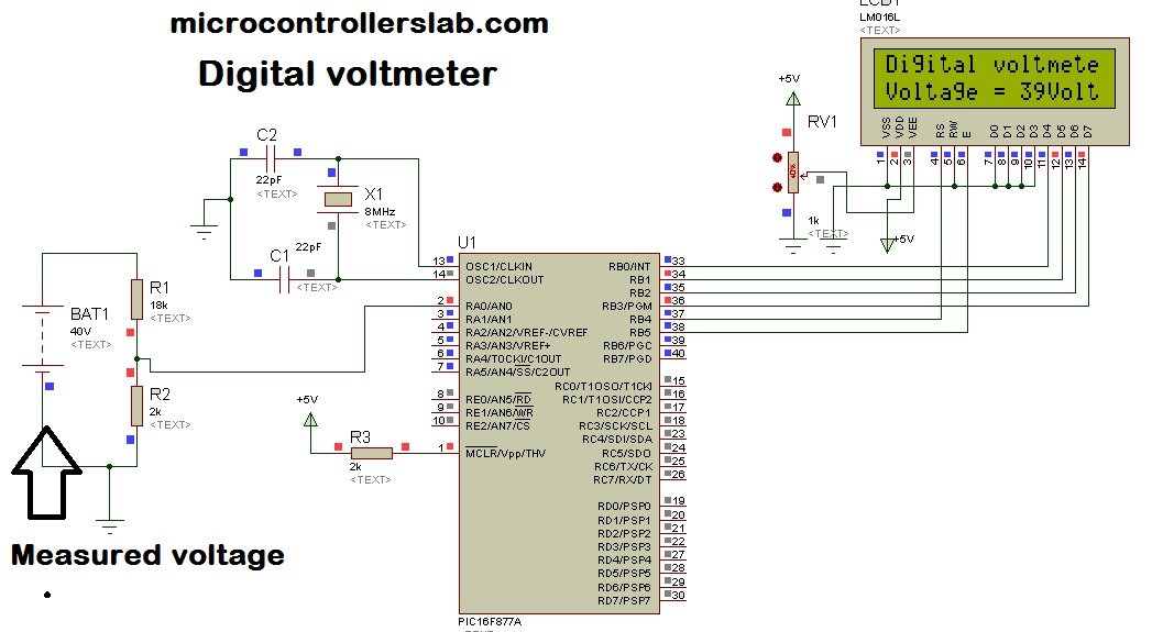
Circuit diagram of digital voltmeter using pic microcontroller and 16×2 LCD is given below. A 40-volt battery is used as a voltage source whose voltage you want to measure. PIC16F877A microcontroller can not directly read 40 volts. The voltage divider circuit using a resistor is used to step down dc voltage appearing across analog to digital converter pin of PIC16F877A microcontroller.
How to Measure Dc Voltage?
Resistor R1=18k and R2=2k are used as voltage dividers. According to voltage division formula, voltage less than 5 volts appears across pic microcontroller in the case of maximum input voltage 40 volts.
Vout = (R2 / R1+R2 ) * Vinput
Vout = ( 2 / 18+2) * 40 = 4 volt
Hence when we apply a maximum input voltage of 40 volts, only 4 volts appear across the pic microcontroller which is less than 5 volt. PIC16F877A microcontroller has seven analogs to digital converter channels. It means it can be interfaced with seven analog channels or it can measure seven analog quantities.
ADC Channel
In this project, AN0/RA0 channel of the pic16F877A microcontroller is used. ADC module of pic microcontroller converts an analog signal into binary numbers. PIC16F877A microcontroller has a 10 bit ADC. So it converts an analog signal to a 10-bit digital number which can be back converted into voltage using the following calculation in the programming of digital voltmeter.
Resolution = (Vrer+ - Vref-) / (1024 -1 ) ;ADC resolution is an important concept to discuss here. Resolution means minimum value of the analog signal for which ADC counter increment by one. For example, pic16f877A microcontroller has 10-bit ADC and it counts binary from 0-1023 for every minimum analog value of the input signal. This minimum analog value is called resolution ADC increment by one. For example, pic16f877A microcontroller has 10-bit ADC and it counts binary from 0-1023 for every minimum analog value of the input signal. This minimum analog value is called resolution.
In this project, we are taking Verf+= 5 volts and Vref- = 0 volt. Hence by using these values in the above formula, this minimum voltage will be:
resolution = (5 - 0 )/ (1023) = 4.8876 mV;It means for every analog signal of 4.87mV, ADC value increments by one.
Simulation Result
Liquid crystal display is used to display values of voltage. As shown in the figure below. The below diagram shows the result of the digital voltmeter using the pic microcontroller and LCD display.

Video lecture
Digital voltmeter Code MikroC
Now, let’s discuss how to write a program for digital dc voltmeter using a pic microcontroller. Above I have discussed the function of each component and its working in dc voltage measurement with pic microcontroller. The code for digital voltmeter is written using the MikroC Pro compiler. Voltage measured by the ADC module of PIC16F877A microcontroller can be calculated by following programming commands:
voltage = ADC_Read(0); // ADC channel zero stores value in variable voltage
voltage = (voltage * 5 * 10)/ (1024); // resolution factor and voltage divider factor
Statement one is used to reading ADC value and stores its value in variable “voltage” and in second statement voltage value is multiplied with resolution factor and voltage divider factor to convert it into actual input voltage value.
Digital Voltmeter Code with LCD Display
This code is written using MikroC for Pic compiler. Create a new project with MikroC compiler by selecting PIC16F877A microcontroller and set frequency to 8MHz. If you don’t know how create new project in mikroC, we suggest you read this post:
sbit LCD_RS at RB4_bit;
sbit LCD_EN at RB5_bit;
sbit LCD_D4 at RB0_bit;
sbit LCD_D5 at RB1_bit;
sbit LCD_D6 at RB2_bit;
sbit LCD_D7 at RB3_bit;

sbit LCD_RS_Direction at TRISB4_bit;
sbit LCD_EN_Direction at TRISB5_bit;
sbit LCD_D4_Direction at TRISB0_bit;
sbit LCD_D5_Direction at TRISB1_bit;
sbit LCD_D6_Direction at TRISB2_bit;
sbit LCD_D7_Direction at TRISB3_bit;
int Adread;
float voltage;
char volt[4];
void main() {

PORTA = 0;
TRISA = 0X01;
PORTB = 0;
TRISB = 0;
LCD_Init();
ADC_Init();
LCD_Cmd(_LCD_CURSOR_OFF);
LCD_Cmd(_LCD_CLEAR);
LCD_Out(1, 1, "Digital voltmeter");
delay_ms(1000);
while (1)
{
voltage = ADC_Read(0);
voltage = (voltage * 5 * 10)/ (1024);
inttostr(voltage,volt); // it converts integer value into string
Lcd_Out(2,1,"Voltage = ");
Lcd_Out(2,11,Ltrim(volt));
Lcd_Out(2,13,"Volt");
}
}
Code Working
Now let’s understand the working of code. First, we used ‘sbit’ to define pins connection with LCD and PIC16F877A. These lines are used to define pic microcontroller pins that will be used with 16×2 LCD.
sbit LCD_RS at RB4_bit;
sbit LCD_EN at RB5_bit;
sbit LCD_D4 at RB0_bit;
sbit LCD_D5 at RB1_bit;
sbit LCD_D6 at RB2_bit;
sbit LCD_D7 at RB3_bit;

sbit LCD_RS_Direction at TRISB4_bit;
sbit LCD_EN_Direction at TRISB5_bit;
sbit LCD_D4_Direction at TRISB0_bit;
sbit LCD_D5_Direction at TRISB1_bit;
sbit LCD_D6_Direction at TRISB2_bit;
sbit LCD_D7_Direction at TRISB3_bit;
These code lines initialize built-in library of ADC module and liquid crystal dislpay.
LCD_Init(); // intialize LCD library
ADC_Init(); // initialize ADC library
LCD_Cmd(_LCD_CURSOR_OFF); // turn off LCD cursor
LCD_Cmd(_LCD_CLEAR); // Clear whatever is written on LCD
LCD_Out(1, 1, "Digital voltmeter"); // print "Digital voltmeter"on first line and first row
delay_ms(1000); // add a delay of one second
This code is placed inside the while(1) loop function and it keeps executing. Inside this loop, ADC_Read(0) reads analog input signal value from AN0/RA0 pins and store this value into a variable “voltage”. Second line converts measured digital value back into analog voltage by multiplying voltage variable with resolution factor and voltage divider scale down factor. After that we display voltage value on LCD second line.
Before printing value on LCD, we first convert integer variable “voltage” into string by using inttostr() routine.
voltage = ADC_Read(0);
voltage = (voltage * 5 * 10)/ (1024);
inttostr(voltage,volt);
Lcd_Out(2,1,"Voltage = ");
Lcd_Out(2,11,Ltrim(volt));
Lcd_Out(2,13,"Volt");
This digital voltmeter using a pic can read voltage only between 0-40 volt. High voltage measurement voltmeter can also be designed using pic microcontroller and difference amplifier. The difference amplifier will be used to step down dc voltage instead of a voltage divider.
Hi.
If I want volt show 100V . how can I calculate .
Hi.
If I want volt show 100V . how can I calculate .
you just have to change values of votage divider resistor
thank you for your e mails .the problem I can not downloading the code of these projects .I like the project of greenhouse control .can you sending the code of greenhouse .best regards
can i get this coding from you
I have an error while building this code in 28th line “Digital voltmeter”,Can U help me,,
what is the error?
hey man. great job here im probably gonna do this type of work next year and your stuff provides great insight for me, so thx. and i would like to know what is that little component on your circuit diagram that is next to the LCD and is kind of red, it’s written 40% on it.Can you please tell me what it is and what is its purpose there. Thank you already man
Hi, what interface will I use to program the PIC 16F877A?
Thank you very much Mr.Bilal
I understood everything, it was very clear except one thing
voltage = (voltage * 5 * 10)/ (1024); resolution factor and voltage divider factor
I tried to build this circuit and code to measure voltage between 0 – 12 V , you used it to measure between 0 – 40 V
I applied this circuit
http://i0.wp.com/microcontrollerslab.com/wp-content/uploads/2015/05/Digital-voltmeter-using-pic-microcontroller2.jpg
I changed the battery (40 V) to 12 V and R1 = 10K , R2 = 5K
I tried also with ( 9 V ), R1 = 5K , R2 = 4K
to make sure the input voltage to MCU is 4 V as you did,
I know to make this circuit measure form 0 – 12V or 0 – 9V I have to change this code depending on the resistors I used
voltage = (voltage * 5 * 10)/ (1024); resolution factor and voltage divider factor
Could you please help me and explain this part of code, and which part do i need to change and why ? please Mr.Bilal I need your help.
Hi bro ….
Plz tell me that i have always volt = 0 ….what’s the problem
I design the same circuit and code …
Thanks alot
Hi,sir
How to display charging percentage on LCD display using microcontroller in power bank
thank you for this project
may i have the source code ?
Hello please How i can show 220V ?
Hello,
What is the use of the Oscillator circuit in the above circuit?
Thanks
bilal , pic has 8 adc channels not 7. you have mentioned that it has 7 adc’ s in the description part.
thanks for correction 🙂
HI Ser, could you please provide the source code C , I using software AVR Evalution and ATMega8535
sitio_kevin@yahoo.com
Thanks
Assalam o alaikum
Sir
Plz tell me that i have always volt = 0 ….what’s the problem
I design the same circuit and code …
Thanks alot
can i use 220 v as input
sir the above project measure 0 to 40 volt.
Great
Hi,
Could you please send me the .hex file for this project because i received an error when i try to complite the code in MicroC.
My Email: stam2302@gmail.com
Many thanks and Best Regards,
Its ok, i found My mistake…
it is very nyce and good to be exchanging knowlede
Hello again,
I have make a test board with pic 16f877a and i am trying first to show on my LCD the message you have write at your code without success. There is no problem with my programmer as i have tested with another hex file and works properly. Could you please advise whats wrong? I am using all the options you have at your video and i have generated the hex file over the Micro C program (Micro C Pro).
Your assistance is much appreciate.
Best Regards,
Hello Bilal,
First of all, thank you for your detailed explanation, it is really useful.
I’m trying to measure voltage across 2 DC sources in series using a PIC microcontroller. I need seperate measurements for each source. Would you please help me in that matter by showing me schematics on how it would be done.
I’d appreciate it if you can contact me on bemob8@gmail.com
Thanks,
BM
hi,
i got the output in the software using the program and circuit mentioned in this page but i m unable to get the output in the hardware.i m using an 18 v battery and trying to display its voltage value.please help
do you have same program which run on MPLAB software.
If i need 1000 vot to show.
How to show 1000 volt
why always voltmeter is used from any point on the circuit and the ground? why not used from one point to another point? for example: measure resistor’s voltage in middle of circuit? NOT USE the ground of reference
Its good but i need the discussion
Can you please tell me how to interface it with using ssd instead of LCD screen
Plz send it to
gaganchandak04@gmail.com
Can you please send me the c code source file for this project. I’ve interfaced as you’ve given & written the same code also but it’s not running of mikro c software
pls send me the correct source code of this protius simulation
when i use voltage devider ckt for 50V dc restistor erly Very heated..So what is solution for that
volt& Meter with LCD & ADC code using please sand
Hello,
It is too much helpful but If I want to show voltage less than 5V so, What can I do..
I know that to show the greater value, we have to change the value of resistor in voltage divider.
Thanks in advance
If you want to measure voltage less than 5 volts. You don’t need to use a voltage divider circuit. Because the ADC of pic microcontroller can measure voltage less than 5V without the need to de-amplification of input voltage signal.
Hello,
Thanks for all information, I am working on the above circuit and design. But this showing me some errors in the coding. When I put the code in mikroC, it shows the error in line 23 and the error is Undeclared identifier ‘Lcd_Init’ in expression. How can I solve this, kindly guide me properly and share the hex file or tell me the solution of that issue please, I am waiting of your response.
Maarij
Thanks
Hello,
Can you please guide me about code. This code is showing error at “LCD_Init”.
Kindly, let me know the solution for this error. Thank you
which compiler you are using?
I am using ‘mikroC PRO for PIC’ for compiling
include LCD library from the library manager.
Hi Microcontrollerslab
Thanks to one thing on which I spend lots of time that was a single word that is Ltrim(volt)
thanks again
your article is very helpful for me and all others
be Happy and live long