In this user guide, we will learn how to use ESP8266 WiFi Module with Arduino and send data from Arduino to the ThingSpeak server. Arduino Uno R3 does not support WiFi capabilities hence we have to use a separate WiFi module to enable WiFi connectivity. Therefore, we will interface and program ESP-01 WiFi module with Arduino to enable WiFi features. We will use Arduino IDE to program our Arduino with ESP-01. AT commands through the serial port that is UART will be used to configure the ESP-01 WiFi module.
Recommended Components
The following components are used in this project or are helpful for building it with the Arduino.
| Component | How it’s used in this project | Buy on Amazon |
|---|---|---|
| Arduino Uno R3 | The main controller board that runs the sketch and drives every component in this project. | Check Price |
| ESP8266 ESP-01 WiFi module | Adds WiFi connectivity so the Arduino can send data to the ThingSpeak server. | Check Price |
| Breadboard | Lets you build and prototype the circuit without soldering. | Check Price |
| Jumper Wires | Used to make all the connections between the Arduino, breadboard, and modules. | Check Price |
As an Amazon Associate we earn from qualifying purchases. Prices and availability are accurate as of the date/time indicated and are subject to change.
ESP8266 WiFi Module

The ESP8266 WiFi module is basically a complete WiFi solution, which has self-contained integrated TCP/IP protocol stack that can be easily connected to the microcontroller for gaining access to any WiFi network. We can connect this module to any microcontroller like pic microcontroller, Arduino and we can use it as a stand-alone device. For connecting this module to any WiFi network, you can just upload the program to this WiFi module and can use to send data to the Web server or getting HTTP requests.
It is widely used in the Internet of things (IoT) and working voltage of this module is 3.3V. We can use this module with our Arduino development boards that are used in simple as well as complex projects in order to provide WiFi to Arduino development boards, as no Arduino development board comes up with built-in WiFi feature so far. So in short, we can say that every ESP8266 module comes up preprogrammed with AT command set firmware and can be plugged with any other development board to act as a WiFi shield.
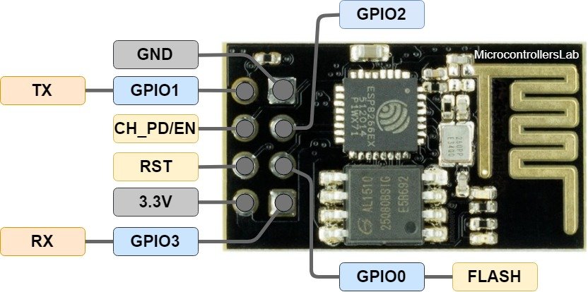
Pin Configuration of ESP8266 WiFi Module
There are many ESP8266 WiFi modules available in marker ranging from ESP-01 to ESP-12. But in this tutorial, we are using ESP-01. AT commands are the same for all these ESP modules. The ESP8266 WIFI module consists of two rows of eight pins.
- Tx - Transmitting pin
- CH-DO – Channel Down pin
- RST – Reset
- VCC – 3.3V power supply
- GND – Power supply ground
- GPIO_2 – Not Used
- GPIO_0 – Not Used
- Rx – Receiver pin
Interfacing Arduino with ESP8266 WiFi Module
This section shows how to connect Arduino UNO with ESP8266 WiFi module.
We will require the following components:
- Arduino UNO
- Three 1k ohm resistors
- ESP-01 Module
- Connecting Wires
- Breadboard
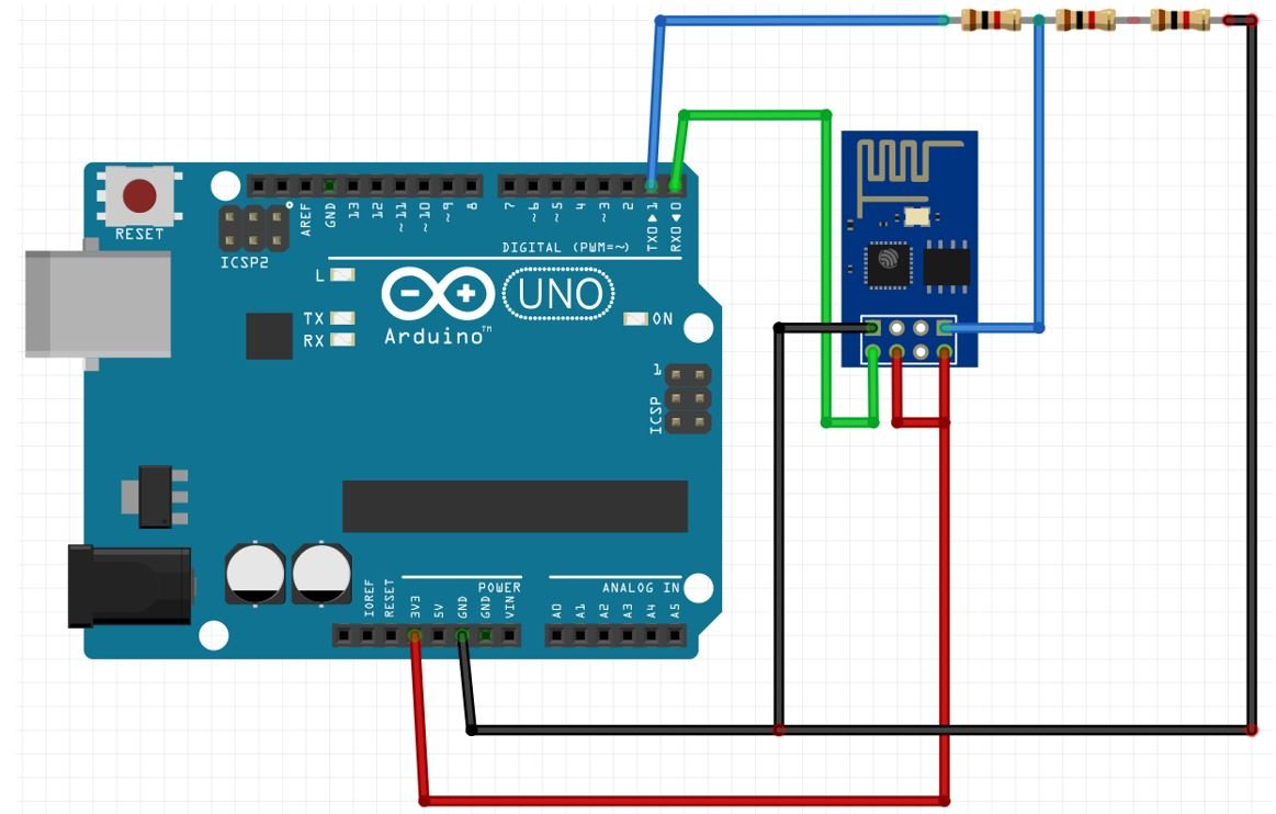
The ESP-01 module consists of 8 pins. However, we will use 5 pins to connect with Arduino. These include the VCC, EN, GND, RX, and TX pins. We will connect RX and TX pins of the module with the virtual UART pins of Arduino.
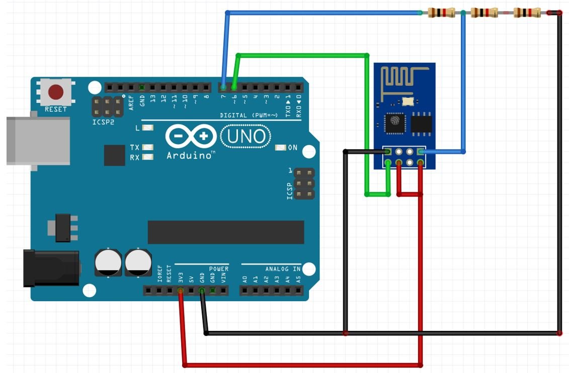
Follow the connection diagram below to connect the two devices.
| ESP-01 | Arduino UNO |
|---|---|
| VCC | 3.3V |
| EN | 3.3V |
| GND | GND |
| TX | Pin 6 |
| RX | Connect RX of ESP-01 with middle point (Junction point of series 1k and 2k resistor) of Voltage divider. The second end of 1k resistor with Pin 7 of Arduino. The second end of 2k resistor with GND pin of Arduino. |
The diagram below shows the connection diagram of Arduino UNO with ESP-01.
Getting ThingSpeak API Ready
ThingSpeak is an open-source API that is used to store or retrieve data using HTTP or MQTT protocol. This takes place over the Internet or through the LAN. We will send data from Arduino connected with the ESP8266 WiFi module to this API. In ThingSpeak you can access your data from anywhere in the world. You can display your data in plots and graphs.
For more information about ThingSpeak API, you can have a look at our previous tutorials given below:
- ESP8266 WiFi Module interfacing with Arduino: Send data to server (ThingSpeak)
- ESP32 HTTP POST using Arduino IDE (ThingSpeak and IFTTT)
- HTTP GET using ESP32 and Arduino IDE (OpenWeatherMap.org and ThingSpeak)
Creating Account
ThingSpeak API is free to use but we will have to create a MathWorks Account.
First go to the following website: https://thingspeak.com/
The following window will appear. Click on the ‘Get Started for Free’ button.

Now you will be redirected to the account window. If you already have an existing MathWorks account you can use that to log in. Otherwise, you will have to create a new one. Click ‘Create One!’ to make a new MathWorks account.

When you have successfully signed in you will receive the following notification:
Click ‘OK’.

Create Channel
We will start by creating a new channel for our project. Go to Channels > My Channels. Then click ‘New Channel’.

You will be prompted to give a name to your channel. We will give a name, some description and mark the first field. You can use any name, description, and field according to your preference. There are a total of eight fields that we can add to our channel at the same time. We will tick the first field and add the name. Click ‘Save Channel’ to proceed.
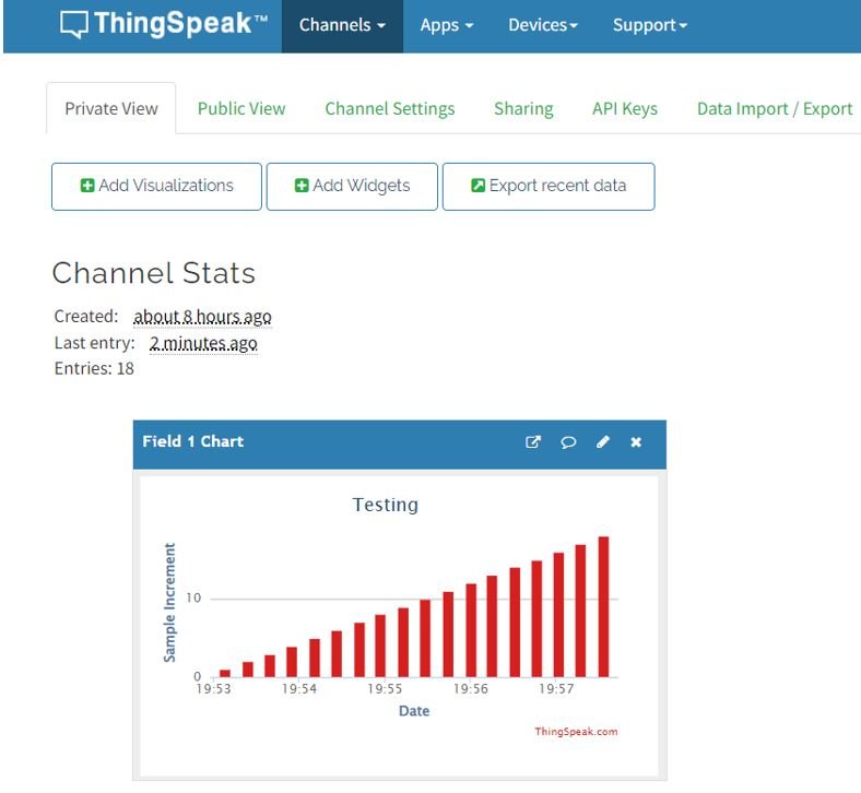
For demonstration purposes, we will send random numbers from 1-100 to the ThingSpeak server.

Your channel will now be created.

Go to private view and click the pencil icon on top of the Field Chart. This will let us customize the graph according to our preference. You can add details accordingly. After you press the Save button, the chart will get updated to the settings you just set.
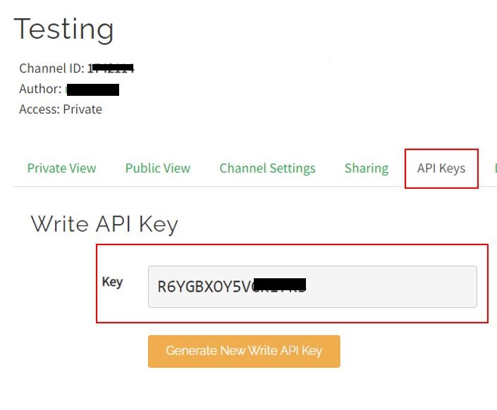
After that go to the API key tab and click it. You will now be able to access your unique write API key. Save it and keep it secure as you will need it later in the program code.
Arduino Sketch Send Data to ThingSpeak
Open your Arduino IDE and go to File > New to open a new file. Copy the code given below in that file. You just have to replace the network credentials and your API key.
#include <SoftwareSerial.h>
SoftwareSerial esp(6, 7);   //Pin 6 and 7 act as RX and TX. Connect them to TX and RX of ESP8266

#define DEBUG true
int number;
String mySSID = "WRITE_YOUR_SSID";  // Wi-Fi SSID
String myPWD = "WRITE_YOUR_PASSWORD"; // Wi-Fi Password
String myAPI = "R6YGBXOY5V******";   // WRITE API Key
String myHOST = "api.thingspeak.com";
String myPORT = "80";
String myFIELD = "field1";

void setup()
{
  Serial.begin(115200);
  esp.begin(115200);
  Send_AT_Cmd("AT+RST", 1000, DEBUG);
  Send_AT_Cmd("AT+CWMODE=1", 1000, DEBUG);
  Send_AT_Cmd("AT+CWJAP=\""+ mySSID +"\",\""+ myPWD +"\"", 1000, DEBUG);
  delay(1000);
}

  void loop()
  {
    number = random(100); // Send a random number between 1 and 100
    String sendData = "GET /update?api_key="+ myAPI +"&"+ myFIELD +"="+String(number);
    Send_AT_Cmd("AT+CIPMUX=1", 1000, DEBUG);       //Allow multiple connections
    Send_AT_Cmd("AT+CIPSTART=0,\"TCP\",\""+ myHOST +"\","+ myPORT, 1000, DEBUG);
    Send_AT_Cmd("AT+CIPSEND=0," +String(sendData.length()+4),1000,DEBUG);
    esp.find(">");
    esp.println(sendData);
    Serial.print("Value to be sent: ");
    Serial.println(number);
    Send_AT_Cmd("AT+CIPCLOSE=0",1000,DEBUG);
    Serial.println("Done!");
    Serial.println("");
    delay(10000);
  }

  String Send_AT_Cmd(String command, const int timeout, boolean debug)
{
  Serial.print(command);
  Serial.println("     ");

  String response = "";
  esp.println(command);
  long int time = millis();
  while ( (time + timeout) > millis())
  {
    while (esp.available())
    {
      char c = esp.read();
      response += c;
    }
  }
  if (debug)
  {
    //Serial.print(response);
  }
  return response;
}
How does the Code work?
Now, let us understand how each part of the code works.
We will require SoftwareSerial.h library to allow serial communication on the digital pins of Arduino that we will be using as Tx and Rx.
#include <SoftwareSerial.h> The following line defines the serial communication virtual Rx pin as Arduino pin 6 and Tx as Arduino pin 7.
SoftwareSerial esp(6, 7);Define DEBUG and set it as true. This will help us show the ESP-01respones on the serial monitor.
#define DEBUG trueWe will specify the WiFi SSID, WiFi password and ThingSpeak write API key. You have to replace these parameters with your own values in order to successfully connect to the local WiFi and send data to the server.
String mySSID = "WRITE_YOUR_SSID";  // WiFi SSID
String myPWD = "WRITE_YOUR_PASSWORD"; // WiFi Password
String myAPI = "R6YGBXOY5V******";   // WRITE API Key
The host, port and field parameters are same for all.
String myHOST = "api.thingspeak.com";
String myPORT = "80";
String myFIELD = "field1";
setup()
Open the serial communication at a baud rate of 115200 for both the serial monitor and ESP8266.
  Serial.begin(115200);
  esp.begin(115200);
Next, initialize the ESP8266 WiFi module through the following AT commands:
AT+RST: This type of command is used for reset the WiFi module when it is in working condition. The response would be ok, when reset the module.
Send_AT_Cmd("AT+RST", 1000, DEBUG);AT+CWMODE=1 : This sets the WiFi mode of ESP8266 in this case in station mode.
Send_AT_Cmd("AT+CWMODE=1", 1000, DEBUG); AT+CWJAP=”SSID”,”PASSWORD” : This connects the ESP8266 with an AP whose SSID and password are given.
Send_AT_Cmd("AT+CWJAP=\""+ mySSID +"\",\""+ myPWD +"\"", 1000, DEBUG); The response time is set to 1 second.
loop()
Inside the loop() function, we first generate a random number between 1-100 and store it in the int variable ‘number.’
number = random(100);Then we will send this number to ThingSpeak dashboard.
    String sendData = "GET /update?api_key="+ myAPI +"&"+ myFIELD +"="+String(number);
    Send_AT_Cmd("AT+CIPMUX=1", 1000, DEBUG);       //Allow multiple connections
    Send_AT_Cmd("AT+CIPSTART=0,\"TCP\",\""+ myHOST +"\","+ myPORT, 1000, DEBUG);
    Send_AT_Cmd("AT+CIPSEND=0," +String(sendData.length()+4),1000,DEBUG);
    esp.find(">");
    esp.println(sendData);
    Serial.print("Value to be sent: ");
    Serial.println(number);
    Send_AT_Cmd("AT+CIPCLOSE=0",1000,DEBUG);
    Serial.println("Done!");
We will create a variable ‘sendData’ that contains a GET request that we will make to ThingSpeak to update the respective field with the value held in the variable ‘number’ converted to a string.
String sendData = "GET /update?api_key="+ myAPI +"&"+ myFIELD +"="+String(number);First we send AT+CIPMUX=1:This command is used to enable multiple connections (maximum 4)
Second, we are write the AT command: “AT+CIPSTART=0,\”TCP\”,\””+ myHOST +”\”,”+ myPORT, 1000, DEBUG. This command is used to set the port connection and address of port.
Next we send the AT command: AT+CIPSEND=’ID’, ‘LENGTH’ This will set the length of the data that will be sent. It tells the WIFI module how many bytes we want to send to the server.
Then we send the data to ThingSpeak which is published to its respective field.
After that, we will close the multiple connections as we are sending the AT command: AT+CIPCLOSE=’ID’.
The response time is set to 1 second.
    Send_AT_Cmd("AT+CIPMUX=1", 1000, DEBUG);       //Allow multiple connections
    Send_AT_Cmd("AT+CIPSTART=0,\"TCP\",\""+ myHOST +"\","+ myPORT, 1000, DEBUG);
    Send_AT_Cmd("AT+CIPSEND=0," +String(sendData.length()+4),1000,DEBUG);
    esp.find(">");
    esp.println(sendData);
    Serial.print("Value to be sent: ");
    Serial.println(number);
    Send_AT_Cmd("AT+CIPCLOSE=0",1000,DEBUG);
Send_AT_Cmd(String command, const int timeout, boolean debug)
We use the following function to send the AT command to the WiFi module. The Send_AT_Cmd(String command, const int timeout, boolean debug) function takes in three parameters: the AT command, the response time and debug.
  String Send_AT_Cmd(String command, const int timeout, boolean debug)
{
  Serial.print(command);
  Serial.println("     ");

  String response = "";
  esp.println(command);
  long int time = millis();
  while ( (time + timeout) > millis())
  {
    while (esp.available())
    {
      char c = esp.read();
      response += c;
    }
  }
  if (debug)
  {
    //Serial.print(response);
  }
  return response;
}
Demonstration
Make sure you choose the correct board and COM port before uploading your code to the board. Go to Tools > Board and select Arduino UNO. Next, go to Tools > Port and select the appropriate port through which your board is connected.

Click on the upload button to upload the code to the board.
After you have uploaded your code to the development board, open the serial monitor and set the baud rate to 115200. In a few moments, the WiFi will get connected. After every few seconds, a new random number will keep appearing as it gets published to its field.
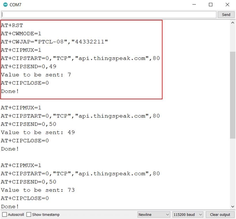
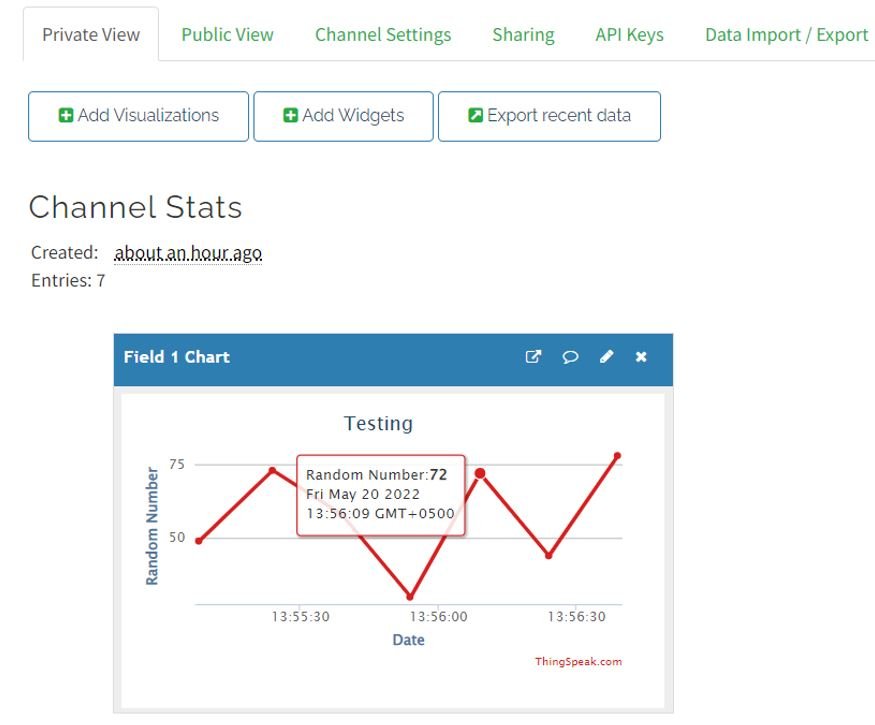
Next, open the ThingSpeak API and you will be able to see the random numbers updating in your chart.
Watch the demonstration below to have a better insight:
Use ESP8266 WiFi Module as a TCP Client with Arduino (Send/Receive Data from Server)
In this section, we will discuss and demonstrate how to use ESP8266 WiFi module as a TCP client with Arduino. We will program our Arduino with the WiFi module in such a manner, that it will be able to send data to a server and also receive from the server. For demonstration purposes, we will send incrementing numbers starting from 0 to the ThingSpeak dashboard. Moreover, to make our coding simpler we will use an ESP8266 AT commands (ESP8266_AT.h) library that will make it easy to connect to WiFi networks, and also implements TCP/IP client and server.
Interfacing ESP8266-WiFi module with Arduino
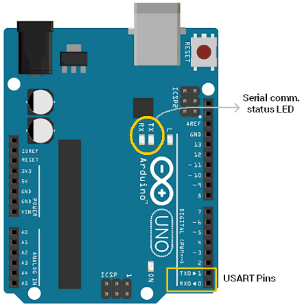
This time however, we will connect ESP8266 WiFi module with the default UART pins of Arduino UNO.
We will require the following components:
- Arduino UNO
- Three 1k ohm resistors
- ESP-01 Module
- Connecting Wires
- Breadboard
The ESP-01 module consists of 8 pins. However, we will use 5 pins to connect with Arduino. These include the VCC, EN, GND, RX, and TX pins. We will connect RX and TX pins of the module with the UART pins TX0 ad RX0 of Arduino respectively.
Follow the connection diagram below to connect the two devices.
| ESP-01 | Arduino UNO |
|---|---|
| VCC | 3.3V |
| EN | 3.3V |
| GND | GND |
| TX | Pin 0 |
| RX | Connect RX of ESP-01 with middle point (Junction point of series 1k and 2k resistor) of Voltage divider. The second end of 1k resistor with Pin 1 of Arduino. The second end of 2k resistor with GND pin of Arduino. |
Arduino Sketch TCP Send and TCP Receive
Open your Arduino IDE and go to File > New to open a new file. Copy the code given below in that file. You just have to replace the network credentials, the ThingSpeak channel ID and the write API key.
#include "ESP8266_AT.h"

 /* Select Demo */
//#define TCP_RECEIVE
#define TCP_SEND

#define HOST          "api.thingspeak.com"
#define PORT            "80"
#define API_WRITE_KEY   "R6YGBXOY5V******"
#define CHANNEL_ID      "1742***"
#define SSID            "WRITE_YOUR_SSID"
#define PASSWORD        "WRITE_YOUR_PASSWORD"

char _buffer[150];
uint8_t Connect_Status;
#ifdef TCP_SEND
uint8_t number = 0;
#endif

void setup() {
    Serial.begin(115200);

    while(!ESP8266_Begin());
    ESP8266_WIFIMode(BOTH_STATION_AND_ACCESPOINT);  /* 3 = Both (AP and STA) */
    ESP8266_ConnectionMode(SINGLE);           /* 0 = Single; 1 = Multi */
    ESP8266_ApplicationMode(NORMAL);          /* 0 = Normal Mode; 1 = Transparent Mode */
    if(ESP8266_connected() == ESP8266_NOT_CONNECTED_TO_AP)/*Check WIFI connection*/
    ESP8266_JoinAccessPoint(SSID, PASSWORD);    /*Connect to WIFI*/
    ESP8266_Start(0, HOST, PORT);
}

void loop() {
    Connect_Status = ESP8266_connected();
    if(Connect_Status == ESP8266_NOT_CONNECTED_TO_AP) /*Again check connection to WIFI*/
    ESP8266_JoinAccessPoint(SSID, PASSWORD);    /*Connect to WIFI*/
    if(Connect_Status == ESP8266_TRANSMISSION_DISCONNECTED)
    ESP8266_Start(0, HOST, PORT);     /*Connect to TCP port*/

    #ifdef TCP_SEND
    memset(_buffer, 0, 150);
    sprintf(_buffer, "GET /update?api_key=%s&field1=%d", API_WRITE_KEY, number++);  /*connect to thingspeak server to post data using your API_WRITE_KEY*/
    ESP8266_Send(_buffer);
    delay(15000);           /* Thingspeak server delay */
    #endif

    #ifdef TCP_RECEIVE
    memset(_buffer, 0, 150);
    sprintf(_buffer, "GET /channels/%s/feeds/last.txt", CHANNEL_ID); /*Connect to thingspeak server to get data using your channel ID*/
    ESP8266_Send(_buffer);
    Read_Data(_buffer);
    delay(600);
    #endif
  }
How the Code Works?
Start off by including the ESP8266_AT.h library. This will make it easy to send the AT commands.
#include "ESP8266_AT.h"Next, if you want to see the demonstration for TCP receive as well then uncomment its definition.
//#define TCP_RECEIVE
#define TCP_SEND
We will specify the WiFi SSID, WiFi password, ThingSpeak write API key and channel ID. You have to replace these parameters with your own values in order to successfully connect to the local WiFi and send data to the server or receive data from the server.
#define SSID            "WRITE_YOUR_SSID"
#define PASSWORD        "WRITE_YOUR_PASSWORD"
#define API_WRITE_KEY   "R6YGBXOY5V******"
#define CHANNEL_ID      "1742***"
Specify the host and port of the ThingSpeak server.
#define HOST          "api.thingspeak.com"
#define PORT           "80"
setup()
Inside the setup() function, we will open the serial commination at a baud rate of 115200. Then we will initialize the ESP8266 Wi-Fi module. First, we will set the Wi-Fi mode as both station and AP. Next, we will check the wi-fi connection and connect to the wi-fi using the SSID and PASSWORD provided. Moreover, we will connect to the TCP port at the specified host and port using ESP8266_Start(0, HOST, PORT).
void setup() {
    Serial.begin(115200);

    while(!ESP8266_Begin());
    ESP8266_WIFIMode(BOTH_STATION_AND_ACCESPOINT);  /* 3 = Both (AP and STA) */
    ESP8266_ConnectionMode(SINGLE);           /* 0 = Single; 1 = Multi */
    ESP8266_ApplicationMode(NORMAL);          /* 0 = Normal Mode; 1 = Transperant Mode */
    if(ESP8266_connected() == ESP8266_NOT_CONNECTED_TO_AP)/*Check WIFI connection*/
    ESP8266_JoinAccessPoint(SSID, PASSWORD);    /*Connect to WIFI*/
    ESP8266_Start(0, HOST, PORT);
}
loop()
We will save the connection status of ESP8266 in the variable ‘Connect_Status.’ Then we will make sure that the ESP8266 Wi-Fi module is connected to Wi-Fi and connected to the TCP port.
    Connect_Status = ESP8266_connected();
    if(Connect_Status == ESP8266_NOT_CONNECTED_TO_AP) /*Again check connection to WIFI*/
    ESP8266_JoinAccessPoint(SSID, PASSWORD);    /*Connect to WIFI*/
    if(Connect_Status == ESP8266_TRANSMISSION_DISCONNECTED)
    ESP8266_Start(0, HOST, PORT);     /*Connect to TCP port*/
Then, to see the demonstration of TCP send we will use the following lines of code. Here we will connect to the ThingSpeak server and send data to the respective field using the write API key. The data that we will send is incrementing numbers starting from 0.
    #ifdef TCP_SEND
    memset(_buffer, 0, 150);
    sprintf(_buffer, "GET /update?api_key=%s&field1=%d", API_WRITE_KEY, number++);
    ESP8266_Send(_buffer);
    delay(15000);           /* Thingspeak server delay */
    #endif
Then, to see the demonstration of TCP receive we will use the following lines of code. Here we will connect to the ThingSpeak server and obtain data using our channel ID. We will receive the last number published to the channel.
    #ifdef TCP_RECEIVE
    memset(_buffer, 0, 150);
    sprintf(_buffer, "GET /channels/%s/feeds/last.txt", CHANNEL_ID);
    ESP8266_Send(_buffer);
    Read_Data(_buffer);
    delay(600);
    #endif
TCP Send Demonstration
Make sure you choose the correct board and COM port before uploading your code to the board. Go to Tools > Board and select Arduino UNO. Next, go to Tools > Port and select the appropriate port through which your board is connected.
As we are using D0 and D1 (Tx and Rx) pins therefore unplug these pins each time you upload the program to Arduino board otherwise the code will not compile.
After you have uploaded your code to the development board, open the serial monitor and set the baud rate to 115200. In a few moments, the Wi-Fi will get connected. After every few seconds, an incrementing number gets published to the field.

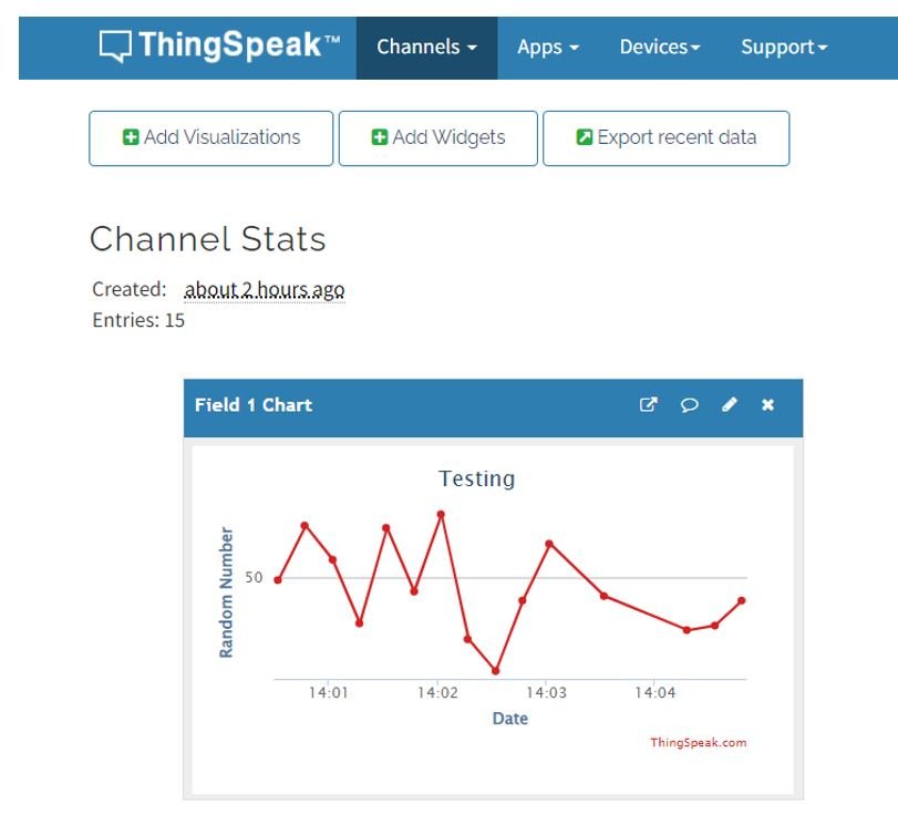
Next, open the ThingSpeak API and you will be able to see the incrementing numbers updating in your chart. Here we have set the chart type to columns to view the values easily.
Hello sir,
Your work is great. Sir, One thing I need to know,if I need to control some led over internet i.e from any where in the world, how to do that, i am using micro controller(Atmega32 and ESP8266 module). My intention is just to use the wifi module as connection bridge with my router connect my micro-controller to internet.
And also sir, how do I get any router’s gateway address and subnet-mask automatically using ESP8266 module.
Can you share the library ESP8266_AT?
but suppose that we have already written some code for our porject then what will happen of that code if write this code in arduino uno.