This guide focuses on TM1637 4 digit 7 segment display module and its interfacing with Arduino. Unlike the 4-Digits 7 segment display which uses 12 pins to connect with a microcontroller, the TM1637 only uses four pins which makes it a very convenient choice of use. We will discuss this module’s description, pinout, and connection with the Arduino board. Then we will discuss an example Arduino sketch which will demonstrate how to program the 4 digits 7 segment module with Arduino. Lastly, we will use the display module to show current temperature readings using the DHT11/DHT22 sensor.
Recommended Reading: Seven Segment Display Interfacing with Arduino
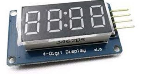
TM1637 4-digit 7 Segment Display Module
TM1637 4 digit display Module is a 4-pin module for digital display through the combination of four 7-segments. The module is basically for a digital display of alphanumeric data. The basic structure of the module is the combination of four 7-segments and two LEDs. The LEDs are used as a ratio sign display. Therefore, the whole LCD comes up with the 12 pins output but TM1637 IC minimizes them to only four pins. The small number of pins of the module and display of data with 7-segment makes it preferable by some developers. The module is quite popular in most commercial and industrial products.
Features
- The use of only two pins can control the four combined 7-segments.
- The device is compatible with Arduino boards with the use of a single library.
- Any alphanumeric value can show on the module from the microcontroller.
- The module TM1637 gives the 8 luminance levels which are adjustable through the programming.
- The device operates on both 3.3V and 5V.
Pinout
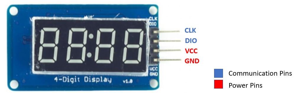
The TM1637 display is popular because of its small number of control pins. Out of these 4 pins, two of them are power pins and the rest two pins control the display value on the module.
| Pin Name | Function |
|---|---|
| CLK | The Clock pin helps to keep the clock pulse sync in with module and microcontroller/Arduino. |
| DIO | The data pin helps in sending and receiving data from the microcontroller/Arduino board. |
| GND | The ground (GND) is pin to make the common ground with external devices. |
| VCC | The power (VCC) input pin to power the module. Accepts 3.3-5V VCC. |
Interfacing TM1637 4 digit 7 segment display module with Arduino
Following components are required:
- Arduino
- TM1637 Module
- Connecting Wires
The connections between the two devices are fairly simple. Follow the schematic diagram below:
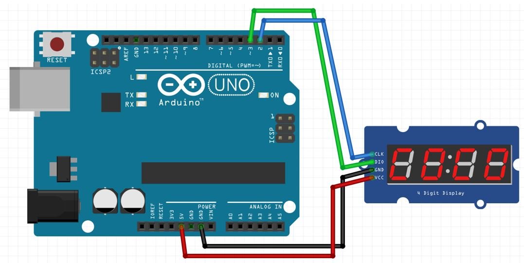
Connect VCC and GND pins of the module with 5V and GND of Arduino board. Additionally, connect CLK and DIO with any appropriate digital pins of the Arduino board. We have used digital pin 2 to connect with CLK and digital pin 3 to connect with DIO respectively.

Installing TMP1637 Library
To program our Arduino board with the TM1637 display module we will require the TM1637 library by Avishay Orpaz. We will use the Arduino library manager to install it easily.
Open your Arduino IDE and go to Sketch > Include Libraries > Manage Libraries. Type ‘TMP1637’ in the search bar and install the latest version of the library shown below:

After installation of the library, restart your IDE.
Arduino Sketch: TM1637 Test
Now to familiarize ourselves with the TM1637 display module let us run the example sketch provided by the TM1637 library by Avishay Orpaz which we just installed. Go to File > Examples > TMP1637 > TM1637Test.
The following code will open up.
#include <Arduino.h>
#include <TM1637Display.h>

// Module connection pins (Digital Pins)
#define CLK 2
#define DIO 3

// The amount of time (in milliseconds) between tests
#define TEST_DELAY   2000

const uint8_t SEG_DONE[] = {
	SEG_B | SEG_C | SEG_D | SEG_E | SEG_G,           // d
	SEG_A | SEG_B | SEG_C | SEG_D | SEG_E | SEG_F,   // O
	SEG_C | SEG_E | SEG_G,                           // n
	SEG_A | SEG_D | SEG_E | SEG_F | SEG_G            // E
	};

TM1637Display display(CLK, DIO);

void setup()
{
}

void loop()
{
  int k;
  uint8_t data[] = { 0xff, 0xff, 0xff, 0xff };
  uint8_t blank[] = { 0x00, 0x00, 0x00, 0x00 };
  display.setBrightness(0x0f);

  // All segments on
  display.setSegments(data);
  delay(TEST_DELAY);

  // Selectively set different digits
  data[0] = display.encodeDigit(0);
  data[1] = display.encodeDigit(1);
  data[2] = display.encodeDigit(2);
  data[3] = display.encodeDigit(3);
  display.setSegments(data);
  delay(TEST_DELAY);

  /*
  for(k = 3; k >= 0; k--) {
	display.setSegments(data, 1, k);
	delay(TEST_DELAY);
	}
  */

  display.clear();
  display.setSegments(data+2, 2, 2);
  delay(TEST_DELAY);

  display.clear();
  display.setSegments(data+2, 2, 1);
  delay(TEST_DELAY);

  display.clear();
  display.setSegments(data+1, 3, 1);
  delay(TEST_DELAY);


  // Show decimal numbers with/without leading zeros
  display.showNumberDec(0, false); // Expect: ___0
  delay(TEST_DELAY);
  display.showNumberDec(0, true);  // Expect: 0000
  delay(TEST_DELAY);
	display.showNumberDec(1, false); // Expect: ___1
	delay(TEST_DELAY);
  display.showNumberDec(1, true);  // Expect: 0001
  delay(TEST_DELAY);
  display.showNumberDec(301, false); // Expect: _301
  delay(TEST_DELAY);
  display.showNumberDec(301, true); // Expect: 0301
  delay(TEST_DELAY);
  display.clear();
  display.showNumberDec(14, false, 2, 1); // Expect: _14_
  delay(TEST_DELAY);
  display.clear();
  display.showNumberDec(4, true, 2, 2);  // Expect: 04__
  delay(TEST_DELAY);
  display.showNumberDec(-1, false);  // Expect: __-1
  delay(TEST_DELAY);
  display.showNumberDec(-12);        // Expect: _-12
  delay(TEST_DELAY);
  display.showNumberDec(-999);       // Expect: -999
  delay(TEST_DELAY);
  display.clear();
  display.showNumberDec(-5, false, 3, 0); // Expect: _-5_
  delay(TEST_DELAY);
  display.showNumberHexEx(0xf1af);        // Expect: f1Af
  delay(TEST_DELAY);
  display.showNumberHexEx(0x2c);          // Expect: __2C
  delay(TEST_DELAY);
  display.showNumberHexEx(0xd1, 0, true); // Expect: 00d1
  delay(TEST_DELAY);
  display.clear();
  display.showNumberHexEx(0xd1, 0, true, 2); // Expect: d1__
  delay(TEST_DELAY);

	// Run through all the dots
	for(k=0; k <= 4; k++) {
		display.showNumberDecEx(0, (0x80 >> k), true);
		delay(TEST_DELAY);
	}

  // Brightness Test
  for(k = 0; k < 4; k++)
	data[k] = 0xff;
  for(k = 0; k < 7; k++) {
    display.setBrightness(k);
    display.setSegments(data);
    delay(TEST_DELAY);
  }

  // On/Off test
  for(k = 0; k < 4; k++) {
    display.setBrightness(7, false);  // Turn off
    display.setSegments(data);
    delay(TEST_DELAY);
    display.setBrightness(7, true); // Turn on
    display.setSegments(data);
    delay(TEST_DELAY);
  }


  // Done!
  display.setSegments(SEG_DONE);

  while(1);
}
This sketch uses different functions provided by the TMP1637 library that will help us to display a decimal number as well as a decimal number with colon or decimal point. Setting the brightness of the display, clearing the display as well as setting the raw value of the segments of each digit.
Let us see how all these different functionalities will be performed.
How the Code Works?
As usual we will start off by including the relevant library needed for the TM1637 4 digit 7 segment display module.
#include <Arduino.h>
#include <TM1637Display.h>
Next, we will define the Arduino digital pins we connected with the CLK and DIO pins of the display module. If you are using different Arduino pins, remember to change them in the code.
// Module connection pins (Digital Pins)
#define CLK 2
#define DIO 3
Then we will create an instance of the TM1637Display library called display() and pass the CLK and DIO pins as parameters inside it.
TM1637Display display(CLK, DIO);To control the individual segments of the display we have two options which we can use.
- In the first case we can define each digit using hexadecimal numbers. We will create two arrays. The first array called data will turn all the segments ON whereas the second array blank turns all the segments OFF. The data array stores the hexadecimal 0xff which is 11111111 in binary. Therefore all the segments are set to ON. On the other hand the blank array stores 0x00 which is 00000000 hence all the segments are set to OFF.
Click here to refer to hexadecimal to binary/decimal conversions.
 uint8_t data[] = { 0xff, 0xff, 0xff, 0xff };
uint8_t blank[] = { 0x00, 0x00, 0x00, 0x00 };- In the second case, we can define individual segments that we want to turn ON. The following code displays “dOne” on the 4 digit 7 segment display module. Notice that each segment is set apart by the | whereas digits are set apart by a comma (,).
const uint8_t SEG_DONE[] = {
	SEG_B | SEG_C | SEG_D | SEG_E | SEG_G,           // d
	SEG_A | SEG_B | SEG_C | SEG_D | SEG_E | SEG_F,   // O
	SEG_C | SEG_E | SEG_G,                           // n
	SEG_A | SEG_D | SEG_E | SEG_F | SEG_G            // E
	};
setBrightness(brightness, true/false)
The setBrightness(brightness, true/false) function takes in a single parameter, the brightness of the display. The second parameter is optional and can take the value ‘true’ or ‘false’ where true means to turn on the display and false means to turn off the display. The brightness of the display can take values from 0x00-0x0f or 0-7 where 0x00 or 0 is the lowest brightness and 0x0f or 7 is the highest brightness.
display.setBrightness(0x0f);setSegments(segments[], length, position)
The setSegments(segments[], length, position) function is responsible to set the individual segments of the display. It takes in three parameters. The first parameter is the segment array that we previously defined. The second parameter is the number of digits from 0 to 4 that we want to change. The third parameter is the position where we will start displaying.
The second and third parameters are optional. The following code will turn on all the segments of the display. The data array stored the hexadecimal 0xff which is 11111111 in binary. Therefore all the segments are set to ON.
display.setSegments(data);The following code will display “dOne” on the display module.
 // Done!
  display.setSegments(SEG_DONE);
The following code first clears the display by using the clear() method on the display object. Then it selectively sets the segments and updates the last two digits using:
 display.clear();
display.setSegments(data+2, 2, 2);
showNumDec(number, leading_zeros, length, position)
The showNumDec(number, leading_zeros, length, position) function is used to display a number on the display. The first parameter which is the number that we want to print is necessary while the rest of the parameters are optional. The second parameter is the leading zeros which can take the value true or false. Setting it to true means that we want to display the leading zeros and setting it to false means we do not want to display the leading zeros. For example, printing 5 with leading zeros will be 0005 and without leading zeros will be just —5.
  // Show decimal numbers with/without leading zeros
  display.showNumberDec(0, false); // Expect: ___0
  delay(TEST_DELAY);

  display.showNumberDec(0, true);  // Expect: 0000
  delay(TEST_DELAY);

  display.showNumberDec(1, false); // Expect: ___1
  delay(TEST_DELAY);

  display.showNumberDec(1, true);  // Expect: 0001
  delay(TEST_DELAY);

  display.showNumberDec(301, false); // Expect: _301
  delay(TEST_DELAY);

  display.showNumberDec(301, true); // Expect: 0301
  delay(TEST_DELAY);
The third and fourth parameters are the length and position. The length meaning the number of digits which will be updated and the position stating the position from which to print.
  display.clear();
  display.showNumberDec(14, false, 2, 1); // Expect: _14_
  delay(TEST_DELAY);

  display.clear();
  display.showNumberDec(4, true, 2, 2);  // Expect: 04__
  delay(TEST_DELAY);

  display.showNumberDec(-1, false);  // Expect: __-1
  delay(TEST_DELAY);

  display.showNumberDec(-12);        // Expect: _-12
  delay(TEST_DELAY);

  display.showNumberDec(-999);       // Expect: -999
  delay(TEST_DELAY);

  display.clear();
  display.showNumberDec(-5, false, 3, 0); // Expect: _-5_
  delay(TEST_DELAY);
showNumDecEx(number, dots, leading_zeros, length, position)
The showNumDecEx(number, dots, leading_zeros, length, position) function is used to display dots between different digits on the display. It takes an additional argument as compared to the showNumDec(number, leading_zeros, length, position) function which is the second argument ‘dots.’ It will be responsible to display dots/colons between different digits.
- For example if displaying a dot between different digits we can use the following arguments and the results will be as follows:
| Argument | Display |
| 0b10000000 | X.XXX |
| 0b01000000 | XX.XX |
| 0b00100000 | XXX.X |
| 0b11100000 | X.X.X.X |
- If displaying a colon between different digits we can use the following argument and the result will be as follows:
| Argument | Display |
| 0b01000000 | XX:XX |
- If displaying a colon and a dot between different digits we can use the following argument and the result will be as follows:
| Argument | Display |
| 0b11100000 | X.X:X.X |
The following piece of code will display the dots at all four positions after a delay.
// Run through all the dots
for(k=0; k <= 4; k++) {
display.showNumberDecEx(0, (0x80 >> k), true);
delay(TEST_DELAY);
}
Demonstration
To see the demonstration of the above code, upload the code to Arduino. Before uploading the code, make sure to select Arduino UNO from Tools > Board.

Also, select the correct COM port to which the Arduino board is connected from Tools > Port.
Once the code is uploaded to your board, the TM1637 display will show all the different numbers.
Watch the video demonstration below:
Displaying Temperature Values (Thermometer) on TM1637 Display using Arduino
Now let us move ahead and build a thermometer which will display the current temperature readings acquired from a DHT11/22 sensor. The sensor will be connected with the Arduino board which we will program with the TM1637 4 digit 7 segment display.
The DHT11/DHT22 is a sensor which measures relative humidity and temperature sensor. It provides a calibrated digital output with a 1-wire protocol. DHT sensors are pre-calibrated. We can directly connect them with Arduino to obtain sensor output reading. They are internally composed of a humidity sensing sensor and a thermistor. These two components measure humidity and temperature. We will only access the temperature readings in this TM1637 display project so let us begin.
DHT11/DHT22 Interfacing with Arduino and TM1637 Module
You will need the following components
Required Components
- Arduino board
- DHT11/DHT22 sensor
- Bread Board
- 10K ohm resistor
- Jumper wires
- TM1637 Module
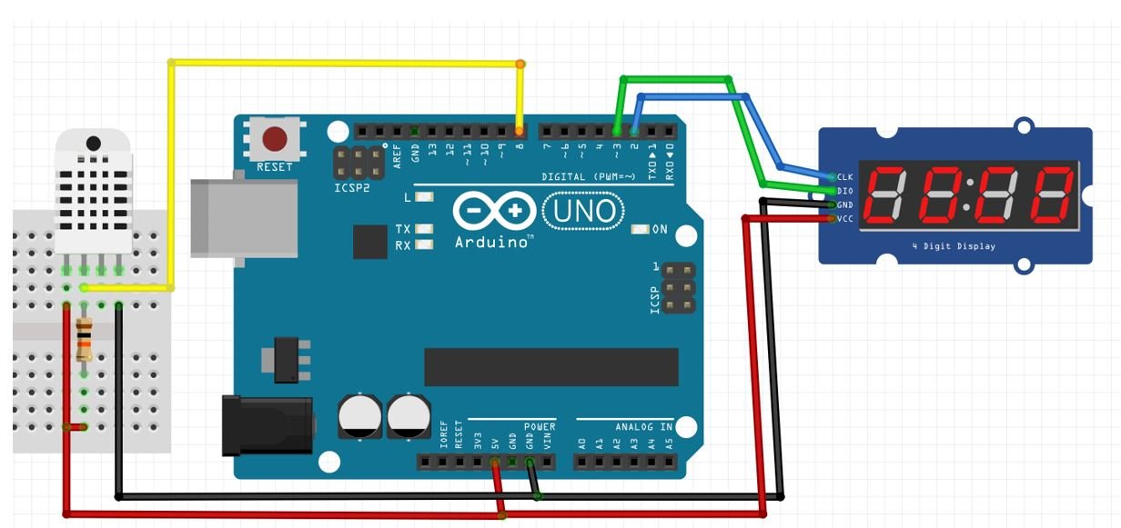
- The first pin for DHT11/22 is the power supply(VCC) pin. Connect it with the 5 volt pin of Arduino which will be common between the VCC of TM1637 module.
- Data out of DHT11/22 is the pin through which we get temperature samples from the DHT sensor. Connect this pin with D8 of Arduino and also connect the data pin with a 10k pull-up resistor. But you can also use any digital pin of Arduino. A Pull-up resistor is used to keep the data pin high for proper communication between the microcontroller and sensor. You can check the datasheet of DHT11 and DHT22 to get more information about it. DHT22 is also known by the name of AM2302.
- Third pin of DHT11/22 is not used.
- Connect the fourth pin (GND) of DHT11/22 to the ground pin of the Arduino board. It is common with GND pin of TM1637 module as well.
- Additionally, connect CLK and DIO pins of TM1637 with any appropriate digital pins of the Arduino board. We have used digital pin 2 to connect with CLK and digital pin 3 to connect with DIO respectively.

You may also like to read:
- DHT11 DHT22 with Arduino – Display Readings on OLED
- ESP32 DHT11 and DHT22 Web Server using Arduino IDE
- DHT11/DHT22 Web Server ESP8266 NodeMCU using Arduino IDE
Installing DHT11/DHT22 Library in Arduino IDE
Both DHT11 and DHT22 provide the output of temperature and humidity in the complex digital output format which can not be directly read with GPIO pins without writing any technique which can read these output signals. These sensors provide data through a single wire two-way communication protocol. A single process communication consists of 40 bits. But we do not need to worry about the working of these sensors and on which protocol we can receive this data. We have an Arduino library for DHT sensors which can be easily used to get values of temperature and humidity only by calling two lines of functions. We will see later on how to do it. Now let’s see how to install the DHT library in Arduino. This library is provided by Adafruit. Follow these steps to install the DHT sensor library.
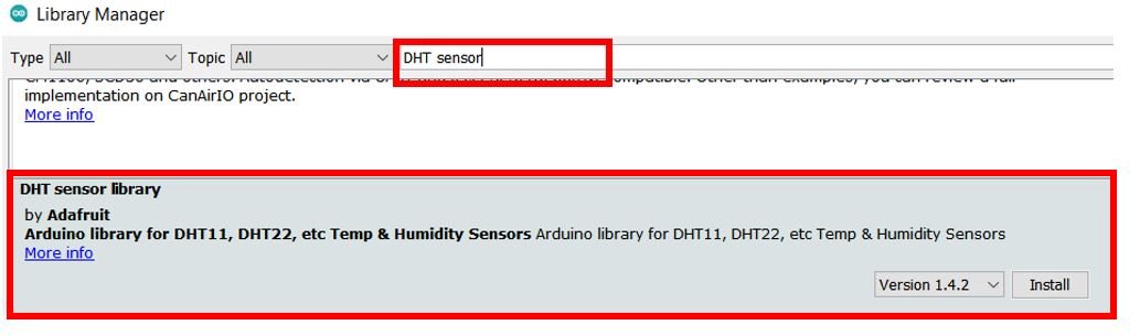
We will use the Arduino library manager to install it easily. Open your Arduino IDE and go to Sketch > Include Libraries > Manage Libraries. Type ‘DHT sensor’ in the search bar and install the latest version of the library shown below:
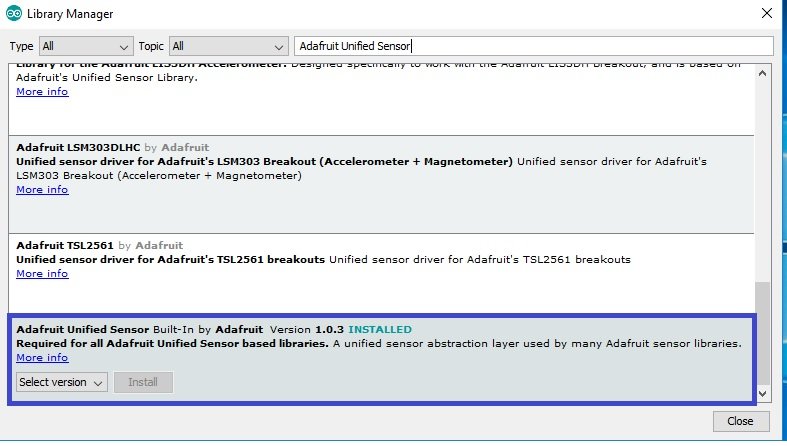
Adafruit also provides libraries for other sensors. So they provided a support package which is used to handle all sensor libraries. We also need to install the Adafruit Unified Sensor library. To install this, paste the Adafruit Unified Sensor search bar and select this option and click on install button.
After installation of the libraries, restart your IDE.
Arduino Sketch Thermometer on TM1637 Display
Open your Arduino IDE and go to File > New. A new file will open. Copy the code given below in that file and save it.
This sketch will acquire current temperature readings from the DHT22 sensor and display the updated readings along with the Celsius sign after every second on the TM1637 display.
#include <TM1637Display.h>
#include <Adafruit_Sensor.h>
#include <DHT.h>

#define CLK 2
#define DIO 3
#define DHTPIN 8

int Temperature;

// Create °C symbol
const uint8_t celsius[] = {
  SEG_A | SEG_B | SEG_F | SEG_G,  // Circle
  SEG_A | SEG_D | SEG_E | SEG_F   // C
};

// Uncomment one of the lines below for whatever DHT sensor type you're using!
//#define DHTTYPE DHT11   // DHT 11
#define DHTTYPE DHT22   // DHT 22


TM1637Display display = TM1637Display(CLK, DIO);
DHT dht = DHT(DHTPIN, DHTTYPE);

void setup() {
 Serial.begin(115200);
  display.setBrightness(0x0f);
  display.clear();
  dht.begin();
}

void loop() {
  Temperature = dht.readTemperature();

    // Check if any reads failed and exit early (to try again).
  if (isnan(Temperature)) {
    Serial.println(F("Failed to read from DHT sensor!"));
    return;
}

  // Display the temperature
  display.showNumberDec(Temperature, false, 2, 0);
  display.setSegments(celsius, 2, 2);
  delay(1000);
}
How the Code Works?
We will start off by including the necessary libraries that are required for this project.
#include <TM1637Display.h>
#include <Adafruit_Sensor.h>
#include <DHT.h>
Next, we will define the Arduino pins that we have connected with TM1637 communication pins as well with the DHT sensor.
#define CLK 2
#define DIO 3
#define DHTPIN 8
Then we will define an integer variable that will hold the temperature readings accessed from the DHT sensor.
int Temperature;The following code will create the degree Celsius sign on the display. We defined the individual segments that we want to turn ON. Notice that each segment is set apart by the | whereas digits are set apart by a comma (,).
// Create °C symbol
const uint8_t celsius[] = {
  SEG_A | SEG_B | SEG_F | SEG_G,  // Circle
  SEG_A | SEG_D | SEG_E | SEG_F   // C
};
This is used to define which type of DHT sensor we want to use. You can use this with DHT11 and DHT22 sensors. You should uncomment the line according to the sensor you are using. For example, we are using DHT22 in this tutorial, we have uncommented this. DHTTYPE variable stores the name of the sensor we are using.
// Uncomment one of the lines below for whatever DHT sensor type you're using!
//#define DHTTYPE DHT11   // DHT 11
#define DHTTYPE DHT22   // DHT 22
This line will create the object of DHT according to our defined pin number and DHT type. We have defined both these parameters previously.
DHT dht = DHT(DHTPIN, DHTTYPE);Then we will create an instance of the TM1637Display library called display() and pass the CLK and DIO pins as parameters inside it.
TM1637Display display = TM1637Display(CLK, DIO);setup()
Inside the setup() function we will set the brightness of the display and initially clear the display. Additionally, we will also initialize the DHT sensor using the begin() method on the dht object.
void setup() {
  Serial.begin(115200);
  display.setBrightness(0x0f);
  display.clear();
  dht.begin();
}
loop()
Inside the loop() function, we will first access the current temperature reading in degrees Celsius from the DHT sensor and save it in the variable ‘Temperature.’
Temperature = dht.readTemperature();
To check, if the Arduino reads the temperature readings correctly, we can use isnan() function.
    // Check if any reads failed and exit early (to try again).
  if (isnan(Temperature)) {
    Serial.println(F("Failed to read from DHT sensor!"));
    return;
}
Finally, we will display the reading with the degree Celsius sign on the TM1637 display using the following lines of code. It will get updated after every second.
  // Display the temperature
  display.showNumberDec(Temperature, false, 2, 0);
  display.setSegments(celsius, 2, 2);
  delay(1000);
Demonstration
To see the demonstration of the above code, upload the code to Arduino. Before uploading the code, make sure to select Arduino UNO from Tools > Board.
Also, select the correct COM port to which the Arduino board is connected from Tools > Port.
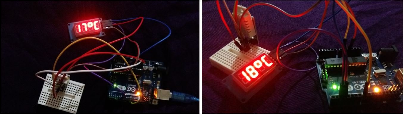
Once the code is uploaded to your board, the TM1637 display will show the current temperature reading in degrees Celsius.
You may also read our other guides on 7 segment displays:
- Interface ESP8266 with 74HC595 and 4-Digit 7 Segment Display
- 74HC595 Interfacing with 7-segment Display and Pic Microcontroller
- Interface ESP32 with 74HC595 and 4-Digit 7 Segment Display
- LM35 Temperature Sensor with 7-Segment Display using Pic Microcontroller
- Digital DC Voltmeter using 7-Segment Display and Pic Microcontroller
- Display ADC value on 4-digit 7-Segment Display using Pic Microcontroller
- 7 Segment Display Interfacing with Pic Microcontroller