In this article, we will learn how to print adc value on 7 segment display using pic microcontroller. In the last two articles, we have seen how to use adc module of pic microcontroller and how to interface seven segment displays with pic microcontroller. But there are many applications where we want to use 7 segment displays instead of liquid crystal displays to show values of different types of sensors such as temperature, voltage, current, humidity etc.
Before starting with this post, you should know how to use the ADC module of pic microcontroller and How to interface seven segment displays:
- How to use ADC Module of Pic Microcontroller?
- How to Interface 7-Segment displays with Pic Microcontroller
ADC Value on 7 Segment Circuit Diagram
In this project, we used a common cathode type 4-digit 7 segment display with a PIC16F877a microcontroller. This circuit shows a connection diagram of the 4-digital 7-segment display, a variable resistor, and PIC16F877A. Pic microcontroller measures the voltage across a variable resistor with analog channel AN0 and shows this measured voltage value on a 4-digit seven-segment display.
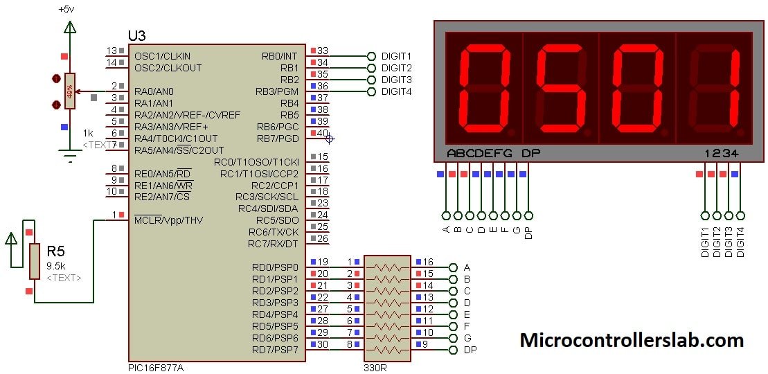
PIC Microcontroller and 7 segment Connections
As you know that each display device consists of 7 LEDs and light-emitting diodes that are used in typical displays require about 10mA current to operate. However, each GPIO pin of Pic microcontroller can provide 25mA current. Therefore, resistors are used to make a connection between PIC16F877A and 4-digital seven segment display module. These resistors act as current limiting resistors. For more information on how to use GPIIO pins of PIC16F877A microcontroller, check this tutorial:
- LED Blinking Example Pic Microcontroller ( Learn to use GPIO pins)
For this tutorial, we used PORTD of PIC16F877A to send binary pattern data to seven-segment displays. Also RB0, RB1, RB2, RB4 pins to control each 7-segment from out of four. Make connections of PORTB with control pins according to this table.
| PIC16F877A | 4-Digit Display pins |
|---|---|
| RB0 | 1 |
| RB1 | 2 |
| RB2 | 3 |
| RB3 | 4 |
This table shows the connections of PORTD of PIC16F877A microcontroller with A-G pins of the seven-segment device through 330ohm resistors.
| PIC16F877A PORTD | 4-digit 7-Segment display pins |
|---|---|
| RD0 | Segment-A |
| RD1 | Segment-B |
| RD2 | Segment-C |
| RD3 | Segment-D |
| RD4 | Segment-E |
| RD5 | Segment-F |
| RD6 | Segment-G |
| RD7 | DIP |
ADC Channel Connection with POT
In order to make a practical demonstration for displaying ADC value on seven segment display, we used one analog to digital converter channel ( AN0/RA0) of PIC16F877A microcontroller. To provide, the analog voltage input to ADC channel AN0, we connected a variable resistor ( which is also known as POT ) to this pin.
A potentiometer is a three terminal passive electronics device. Connect one terminal with positive terminal of 5 volts, other terminal with ground and center terminal with ADC pin of PIC16F877A microcontroller. Now, if we rotate the knob of POT according to increasing or decreasing resistance terminal, voltage also rise or fall on analog input pin (AN0).
MikroC Code
This is a complete code to print ADC value on a 4-digit seven-segment display in Mikroc for Pic compiler. If you have no idea about MikroC and if you don’t know how to create a project with this compiler, you can read this post:
// define name to each control signal for 7-segment
sbit digit1 at PORTB.B0;
sbit digit2 at PORTB.B1;
sbit digit3 at PORTB.B2;
sbit digit4 at PORTB.B3;
// This array stores binary bit pattern that will be send to PORTD
unsigned char binary_pattern[]={0x3F,0x06,0x5B,0x4F,0x66,0x6D,0x7D,0x07,0x7F,0x6F};
unsigned int a1,a2,a3,a4; // temporary variables to store data of adc
int adc_value; //store output value from Analog Read functoion
void split_data()
  {
  a1 =  adc_value / 1000;   // holds 1000's digit
  a2 = ((adc_value/100)%10); // holds 100's digit
  a3 = ((adc_value/10)%10);  // holds 10th digit
  a4 = (adc_value%10);  // holds unit digit value
   }

void display_data()
 {
  PORTD = binary_pattern[a1]; // send 1000's place data to fourth digit
  digit1 = 0;   //  turn on forth display unit
  delay_ms(3);
  digit1 = 1;   //  turn off forth display unit
  PORTD = binary_pattern[a2];  // send 100's place data to 3rd digit
  digit2 = 0;    //  turn on 3rd display unit
  delay_ms(3);
  digit2 = 1;  //  turn off 3rd display unit
  PORTD = binary_pattern[a3];  // send 10th place data to 2nd digit
  digit3 = 0;  //  turn on 2nd display unit
  delay_ms(3);
  digit3 = 1;   //  turn off 2nd display unit
  PORTD=binary_pattern[a4];  // send unit place data to 1st digit
  digit4 = 0;  //  turn on 1st display unit
  delay_ms(3);
  digit4 = 1;  //  turn off 1st display unit
   }
void interrupt()
{

 split_data();   // call function to split data
 display_data(); //call display_data() function to output value to seven segment
 T0IF_bit = 0;  // clear source of timer0 interrupt
}
void main(void)
{
    TMR0   = 0;         // timer0 reset bit
    OPTION_REG = 0x83;  // select prescalar value 1:16 for timer0
    INTCON = 0xA0;      // turn on global interrupt and timer0 overflow interrupt
    TRISD = 0x00; //define PORTD as a output pin
    PORTD=0x00;   // initialize PORTD pins to active low
    TRISB=0x00;// Set PORTB as a output port
  // set control pins pins initially active high
    digit1 = 1;
    digit2 = 1;
    digit3 = 1;
    digit4 = 1;

    while(1)
    {

           adc_value = ADC_Read(0);  // read data from channel 0
           //delay_ms(100);  // wait 100 milliseconds

    }

}
Proteus Simulation Result
First, let’s see the working of the above code with the help simulation that we designed in proteus. After that, we will explain the working of MikroC program.
As you can see from this proteus simulation, as soon as we make a change to a variable resistor, ADC value also changes on the 4-digit seven-segment display. ADC value varies between 0 and 1023. Because PIC17F877A has 10-bit ADC channels. That means it converts, it converts 0-5 volts into equivalent 0-1023 levels of digital value. Therefore, when the POT terminal reaches 5 volts, we see 1023 on the display and otherwise, it prints values according to the analog voltage level.

Code Working
At the start, we define names for pins used to as control signals that are used to control the display of each seven-segment from out of four such as digit1, digit2, digit3, and digit4. For example, we used RB0, RB1, RB2 and RB3 pins of PORB to control the display of digit one, two, three and four respectively. Now, throughout the program, we will use these defined names instead of pin names. It will make the code easier to read.
// define name to each control signal for 7-segment
sbit digit1 at PORTB.B0;
sbit digit2 at PORTB.B1;
sbit digit3 at PORTB.B2;
sbit digit4 at PORTB.B3;
Here binary_pattern array consists of hex values of binary patterns according to the number that we want to display. An array is a data type just like int, float or char but it can hold a collection of similar data types. For instance, this line defines a character type array that consists of 10 characters type numbers.
Similarly, other temporary variables are also used. The variable adc_value stores digital value from the output of adc_read functions and we will display this value on the 4-digit seven-segment device. The variables a1, a2, a3, and a4 are used to store first, second, third and fourth digit values
unsigned char binary_pattern[]={0x3F,0x06,0x5B,0x4F,0x66,0x6D,0x7D,0x07,0x7F,0x6F};
unsigned int a1,a2,a3,a4; // temporary variables to store data of adc
int adc_value; //store output value from Analog Read functoion
Split data() function extracts digits for thousands, hundreds, 10th and unit place from counter value. These global variables a1, a2, a3, and a4 retrieve 1000’s, 100’s, 10th and unit digits data.
void split_data()
  {
           a1 =  adc_value / 1000;   // holds 1000's digit
           a2 = ((adc_value/100)%10); // holds 100's digit
           a3 = ((adc_value/10)%10);  // holds 10th digit
           a4 = (adc_value%10);  // holds unit digit value
   }
This function prints data on a 4-digital 7-segment display by selecting each seven-segment device one by one. We add a delay of 3 milliseconds before sending data to each digit device. We cannot send data to all digits at a time. Because the same GPIO pins are used for all segments.
But generally, microcontrollers operate at very high frequency and our humans can’t able to detect this small delay of 3 milliseconds.
void display_data()
 {
    PORTD = binary_pattern[a1]; // send 1000's place data to fourth digit
    digit1 = 0;   //  turn on forth display unit
    delay_ms(3);
    digit1 = 1;   //  turn off forth display unit
    PORTD = binary_pattern[a2];  // send 100's place data to 3rd digit
    digit2 = 0;    //  turn on 3rd display unit
    delay_ms(3);
    digit2 = 1;  //  turn off 3rd display unit
    PORTD = binary_pattern[a3];  // send 10th place data to 2nd digit
    digit3 = 0;  //  turn on 2nd display unit
    delay_ms(3);
    digit3 = 1;   //  turn off 2nd display unit
    PORTD=binary_pattern[a4];  // send unit place data to 1st digit
    digit4 = 0;  //  turn on 1st display unit
    delay_ms(3);
    digit4 = 1;  //  turn off 1st display unit
   }
This interrupts function update value on 4-digital 7-segment display after every 400 microseconds approximately. Timer0 of PIC16F877A microcontroller is used to generate a delay of 400 microseconds. On interrupt, the microcontroller suspends every other work and executes this interrupt function. Inside this routine, first, it calls split_data() function that extracts digit values from ADC output. If you don’t know how to use pic microcontrollers timers, you can read this article:
After that display_data() function is called that prints digit values.
void interrupt()
{
            split_data();   // call function to split data
            display_data(); //call display_data() function to output value to seven segment
            T0IF_bit = 0;  // clear source of timer0 interrupt
}
Inside the main() function, we declare GPIO pins as output pins, initialize timer0 of the PIC16F877A microcontroller. Also, initialize control pins to active high. Because we used a common cathode type 7-segment device.
    TMR0   = 0;         // timer0 reset bit
    OPTION_REG = 0x83;  // select prescalar value 1:16 for timer0
    INTCON = 0xA0;      // turn on global interrupt and timer0 overflow interrupt
    TRISD = 0x00; //define PORTD as a output pin
    PORTD=0x00;   // initialize PORTD pins to active low
    TRISB=0x00;// Set PORTB as a output port
  // set control pins pins initially active high
    digit1 = 1;
    digit2 = 1;
    digit3 = 1;
    digit4 = 1;
Hey I have some troubles with the code I can’t compile for some errors do you have the “.hex?”
Please share the issue you are facing so that we can guide you accordingly
Do you have the code in .asm?
you can convert this code into assembly by using MiKroC or MPLAB.
Hi Maestro
The Proteus is like yours
The code mikroC is like yours
Same PIC16F877A
But there is no display.
I cannot locate the problem.
Thanks in advance
Please check your circuit connections and also see if you are selected the correct crystal frequency.
Circuit connections is good
Crystal frequency is 8Mh and changed always to 20Mhz but same.
IS it possible to send you the code to check if there are any errors ?
Hey I have some troubles with the code I can’t compile for some errors
build dose not work
undeclare identifier “ADC_Read” in expression.
what can i do now
which compiler are you using?
hi sir I want to make this project on 8051 with voltage and current meter can you send me the code if you have please or describe