This guide focuses on the 4 digit 7 segment display and its interfacing with ESP32 using 74HC595 shift register. By using the 74HC595 shift register to drive 7-segment displays with our ESP boards, we can save GPIO pins of ESP32. First, we will show you some descriptions of 7 segment displays and 74HC595 IC and then we will provide you a code to program your ESP32 boards in Arduino IDE. Using the code you will be able to display numbers from 0-9999 on your 4 digit seven segment display easily.
We have a similar guide with ESP8266 NodeMCU:
Before heading over to our HS420361K-32 4 digit 7 segment display let us first briefly introduce you to 7 segment displays.
Recommended Components
The following components are used in this project or are helpful for building it with the ESP32.
| Component | How it’s used in this project | Buy on Amazon |
|---|---|---|
| ESP32 Development Board (DevKit V1) | The main controller that runs the project code and connects to the components. | Check Price |
| Micro USB Cable | Connects the ESP32 to your computer for programming and power. | Check Price |
| Breadboard | Lets you build the circuit and wire up parts without soldering. | Check Price |
| Jumper Wires | Make the connections between the ESP32 and the components on the breadboard. | Check Price |
| 74HC595 shift register | Expands ESP32 outputs to drive the 7-segment display with fewer pins. | Check Price |
| 4-digit 7-segment display | Shows the digits output by the ESP32 through the shift register. | Check Price |
As an Amazon Associate we earn from qualifying purchases. Prices and availability are accurate as of the date/time indicated and are subject to change.
7 Segment Display Introduction
A 7-segment device consists of 7 light emitting diodes. These light-emitting diodes are arranged and packed inside a single display with a specific pattern in mind. If this pattern is controlled in a specific way by turning on and turning off LEDs, a seven-segment device will display a unique number. There is also an extra eighth LED on a seven-segment display which is used to display dots. This dot is sometimes used as a decimal point when we want to display a fractional value.
The picture below shows a 7 segment display and its pinout. The string of eight LEDs on the left side shows the internal connection and a picture on the right side shows how these LEDs are arranged to make a seven-segment display. Pin3 and 8 are common pins. These pins are used to provide either 5 volt or ground in common-anode and common cathode type displays respectively.
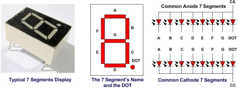
Types of Seven Segment Displays
There are two types of seven segment displays such as common anode and common cathode.
Common Anode Display
In common anode display, all the anodes terminals of eight light emitting diodes are common and connect with 5 volt power supply. In normal condition, we apply logic high from our microcontroller to each segment. Therefore, each segment remains off or does not glow. Similarly, when we want to turn on a specific LED of a seven-segment device, we provide logic low signal. Because LED glows only when there will be a logic high signal on anode side and logic low signal on cathode side such is the case of common anode type display.
Common Cathode Display
In common cathode segment display, all the cathodes of eight light emitting diodes are common and connect with the ground. In order to turn off any segment of 7-segment, we apply logic low from our microcontroller to this segment. Similarly, when we want to turn on a specific LED of a seven-segment device, we provide logic high signal from the microcontroller digital output pin. Because LED glows only when there will be a logic high signal on anode side and logic low signal on cathode side such is the case of common cathode type display.
Recommended Reading: Seven Segment Display Interfacing with Arduino
HS420561K-32 4 digit 7 segment display
A 4 digit 7 segment display we will use in this guide is shown below:
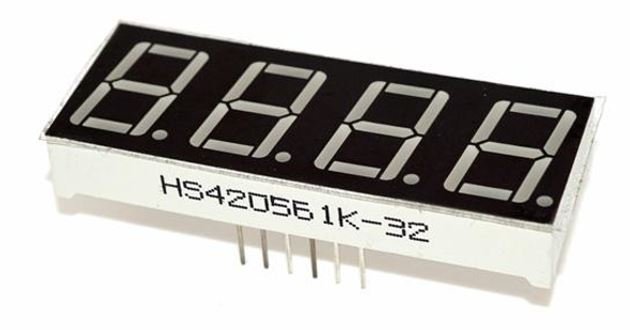
It comes with 12 pins, 6 on either sides. The figure below shows its pin configuration.
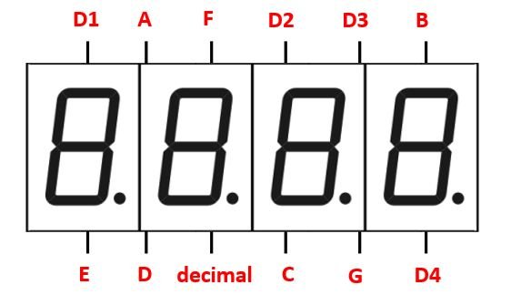
The table below shows the pin number associated with each segment.
| Pin Number | Segment |
| 1 | E |
| 2 | D |
| 3 | decimal |
| 4 | C |
| 5 | G |
| 6 | D4 |
| 7 | B |
| 8 | D3 |
| 9 | D2 |
| 10 | F |
| 11 | A |
| 12 | D1 |
This is a common cathode display. Each segment pin for example A, B, C, D, E, F, G and decimal is responsible for controlling the same segments for all the digits. The digit pins are separate D1, D2, D3 and D4 and are connected to its respective digit1-digit4 respectively. As it is common cathode configuration thus sending a LOW signal to the digit pin turns it ON. Therefore to control each digit we will have to first turn ON/OFF the digit pin D1-D4 of each of the digit. This will be done by providing a HIGH signal to the digit pin. Then we will have to turn on the individual segments to display a number.
74HC595 Shift Register
The 74HC595 is a serial-in and parallel-out shift register IC.
We can use shift registers such as 74HC595 to save microcontrollers pins. With the use of a 74HC595 shift register IC, we can reduce the number of pins to maximum four to control the 4-digit seven-segment device.
The shift register controls several outputs simultaneously. Using serial in parallel out protocol, it obtains data serially from the ESP32 board and transmits it through the parallel pins.
Pin Out
The figure below shows the pin out of the IC.
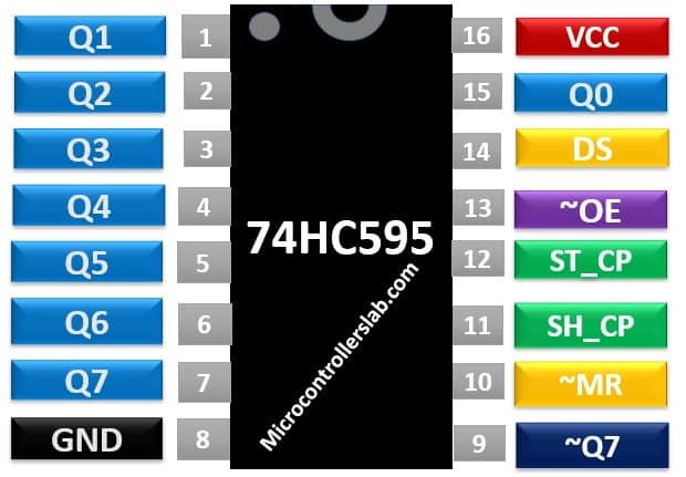
It consists of 16 pins. The eight pins (Q0-Q7) are the output pins of the shift register. These pins are connected with any peripheral where we want to display storage register data in our case the 4 digit 7 segment display.
Functionality of the Pins
This table lists working of each pin.
| Pin Number | Pin Name | Description |
| 1-7, 9, 15 | Q0-Q7 and ~Q7 | 8-bit output register and ~Q7 used for cascading |
| 14 | DS | This is the serial data input pin, where input data is provided. |
| 13 | ~OE | The Output Enable pin is active low. When this pin is low, the data in the storage register appears at the output. On applying high signals, outputs are turned off by forcing them into the high-impedance state. However, serial output is not affected at all. For normal operations, it is kept low. |
| 10 | ~MR | It is an asynchronous, active low master reset Input which is used to reset the shift register only. The 8-bit latch is not affected by this input. Applying a low signal at pin 10 will reset the shift register portion only. |
| 11 | SH_CP | This is the clock input pin of a 74hc595 shift register. A data is shifted from the serial input pin to the 8-bit shift register on every positive transition of the clock signal applied at this pin. |
| 12 | ST_CP | This is the latch pin. It is active high, clock input pin of a storage register. A positive transition of a signal at this pin is used to update the data to the output pins. |
| 8 | GND | This is the ground pin and is connected to the ground of the circuit. |
| 16 | VCC | A positive power supply is provided at this pin. |
For further information on 74HC595 serial shift register, check this link:
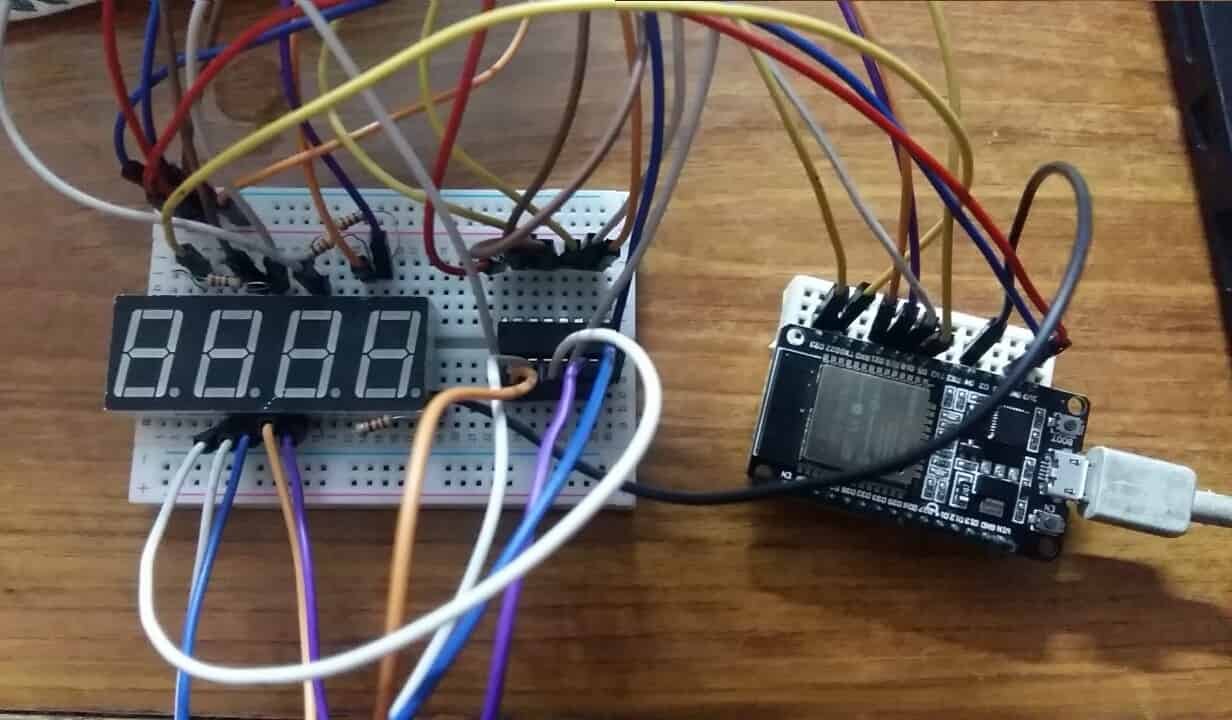
Interfacing ESP32 with 74HC595 and 4 digit 7 segment display
Following components are required:
- ESP32 development board
- 74HC595 IC
- 4 digit 7 segment display
- Four 220 ohm resistors
- Connecting Wires
- Breadboard
In order to properly connect all the devices successfully follow the connections very carefully. Follow the schematic diagram below:
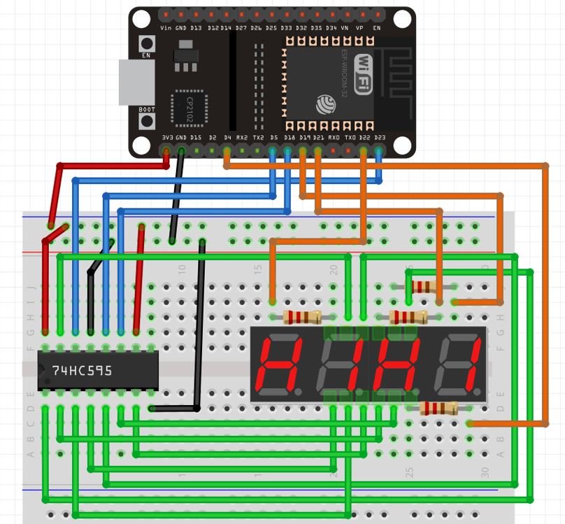
Shift Register with ESP32
Firstly, we will explain the connections between the shift register and the ESP32 board. Start off by connecting pin16 and pin10 of 74HC595 with 3.3V pin of ESP32. Next connect pin8 and pin13 of the IC with the ES32 board. Then we will connect the 3 pins, pin11, pin12 and pin14 with GPIO18, GPIO5 and GPIO23 respectively. These are the clock, latch and data pins.
| 74HC595 | ESP32 |
| pin16 (VCC) and pin10 (~MR) | 3.3V |
| pin8 (GND) and pin13 (~OE) | GND |
| pin11 (SH_CP) | GPIO18 |
| pin12 (ST_CP) | GPIO5 |
| pin14 (DS) | GPIO23 |
Shift Register with 4 digit 7 segment Display
Next, we will explain the connections between the shift register and the 4 digit 7 segment display. Follow the connections shown in the table below to connect the parallel data output pins of the shift register Q0-Q7 with the segments of the display.
| 74HC595 | 4 digit 7 segment display |
| Q0 (pin15) | A |
| Q5 (pin5) | F |
| Q1 (pin1) | B |
| Q4 (pin4) | E |
| Q3 (pin3) | D |
| Q7 (pin7) | decimal |
| Q2 (pin2) | C |
| Q6 (pin6) | G |
4 digit 7 segment Display with ESP32
Lastly, we will explain the connections between ESP32 and the 4 digit 7 segment display. Use four appropriate digital output pins of ESP32 to connect with each of the digit pin D1-D4 through current limiting resistors of 220 ohms each. We have used the pins specified in the table below.
| 4 digit 7 segment Display | ESP32 |
| D1 | GPIO22 |
| D2 | GPIO21 |
| D3 | GPIO19 |
| D4 | GPIO4 |
Setting up Arduino IDE
We will program our ESP32 board using Arduino IDE. Before we proceed further, you should make sure that you have the latest version of Arduino IDE installed on your system. Moreover, you should also install an ESP32 add-on in Arduino IDE. If your IDE does not have the plugin installed you can visit the link below:
Installing ESP32 library in Arduino IDE and upload code
To program our ESP32 board with the shift register and the 4 digit 7 segment display we will require the Timer library by JChristensen from the following link.
Your zip file will get downloaded to your computer right away. After the download is complete, extract the .zip file to the Arduino library folder. Make sure you rename the extracted file as ‘Timer.’ You can also go to Sketch > Include Library > Add .zip Library inside the IDE to add the library as well.
After installation of the library, restart your IDE.
Arduino Sketch: ESP32 4 digit 7 segment display Numbers
Open your Arduino IDE and go to File > New to open a new file. Copy the code given below in that file.
This sketch will enable the user to type any number from 0-9999 which then gets displayed in the 4 digit 7 segment display.
#include "Timer.h"
Timer timer;

long number = 0;
int num1 = 0;
int num2 = 0;
int num3 = 0;
int num4 = 0;
int timer_event = 0;

int D1 = 22;
int D2 = 21;
int D3 = 19;
int D4 = 4;

int latchPin = 5;
int clockPin = 18;
int dataPin = 23;

int count = 0;
int numbers[4] ;
int cathodePins[] = {22, 21, 19, 4};

byte table[10] {B11111100, B01100000, B11011010, B11110010, B01100110, B10110110, B10111110, B11100000, B11111110, B11110110};

void setup() {
  Serial.begin(115200);
  pinMode(D4, OUTPUT);
  pinMode(D3, OUTPUT);
  pinMode(D2, OUTPUT);
  pinMode(D1, OUTPUT);
  pinMode(clockPin, OUTPUT);
  pinMode(latchPin, OUTPUT);
  pinMode(dataPin, OUTPUT);
  digitalWrite(D4, HIGH);
  digitalWrite(D3, HIGH);
  digitalWrite(D2, HIGH);
  digitalWrite(D1, HIGH);
  Serial.println("Enter a number between 0 and 9999");
}

void loop() {
  timer.update();
  if (Serial.available()) {
    timer.stop(timer_event);
    screenOff();
    String s = Serial.readString();
    number = (long)s.toInt();
    if (number > 9999) {
      Serial.println("Enter a number between 0 and 9999");
      } else {
      separate(number);
      timer_event = timer.every(1, Display);
    }
  }
}

void separate(long num) {
  num1 = num / 1000;
  numbers[0] = num1;
  int num1_remove = num - (num1 * 1000);
  num2 = num1_remove / 100;
  numbers[1] = num2;
  int num2_remove = num1_remove - (num2 * 100);
  num3 = num2_remove / 10;
  numbers[2] = num3;
  num4 = num2_remove - (num3 * 10);
  numbers[3] = num4;
}

void Display() {
  screenOff();
  digitalWrite(latchPin, LOW);
  shiftOut(dataPin, clockPin,LSBFIRST, table[numbers[count]]);
  digitalWrite(cathodePins[count], LOW);
  digitalWrite(latchPin, HIGH);
  count++;
  if (count == 4) {
    count = 0;
  }
}

void screenOff() {
  digitalWrite(D4, HIGH);
  digitalWrite(D3, HIGH);
  digitalWrite(D2, HIGH);
  digitalWrite(D1, HIGH);
}
How the Code Works?
We will start by including the Timer.h library that we previously installed. Then we will create a object of that library called ‘timer.’
#include "Timer.h"
Timer timer;
Next we will define the GPIO pins we have connected with each D1-D4 pins of the display.
int D1 = 22;
int D2 = 21;
int D3 = 19;
int D4 = 4;
Additionally, we will also define the latch pin, clock pin and the data pin which we have connected with the ESP32 board.
int latchPin = 5;
int clockPin = 18;
int dataPin = 23;
Next, we will create an integer array that will possess the GPIO pins we have connected with D1, D2, D3 and D4 of the 4 digit 7 segment display respectively.
int cathodePins[] = {22, 21, 19, 4};The following defines the logic signals that we need to provide to LED segments in order to display a specific digit number on a seven segment display.
byte table[10] {B11111100, B01100000, B11011010, B11110010, B01100110, B10110110, B10111110, B11100000, B11111110, B11110110};setup()
Inside the setup() function, we will open a serial connection at a baud rate of 115200.
Serial.begin(115200); Using the pinMode() function we will configure pins D1-D4 as well as the clock, latch and data pin as output pins.
  pinMode(D4, OUTPUT);
  pinMode(D3, OUTPUT);
  pinMode(D2, OUTPUT);
  pinMode(D1, OUTPUT);
  pinMode(clockPin, OUTPUT);
  pinMode(latchPin, OUTPUT);
  pinMode(dataPin, OUTPUT);
Then using the digitalWrite() function we will set all the digit pins to HIGH. This will turn off the display.
  digitalWrite(D4, HIGH);
  digitalWrite(D3, HIGH);
  digitalWrite(D2, HIGH);
  digitalWrite(D1, HIGH);
loop()
Inside the loop() function we will start the timer and acquire if any data is available serially. It is first saved as a string and later converted to an integer. Then we will set up a condition that if the number entered is an invalid number meaning that it is greater than 9999 then the serial monitor will display “Enter a number between 0 and 9999.” Otherwise the user defined separate() function will be called. This function will separate the number into 4 digits. Moreover, we will also call the user defined screenOff() function in the loop(). This will make sure that the display will be off initially.
After separting the number we will do the multiplexing using the every() function. This function is provided by the timer class. It calls the user defined function Display() after every 1 ms.
void loop() {
  timer.update();
  if (Serial.available()) {
    timer.stop(timer_event);
    screenOff();
    String s = Serial.readString();
    number = (long)s.toInt();
    if (number > 9999) {
      Serial.println("Enter a number between 0 and 9999");
      } else {
      separate(number);
      timer_event = timer.every(1, Display);
    }
  }
}
separate()
The separate() function will separate the number into 4 digits.
void separate(long num) {
  num1 = num / 1000;
  numbers[0] = num1;
  int num1_remove = num - (num1 * 1000);
  num2 = num1_remove / 100;
  numbers[1] = num2;
  int num2_remove = num1_remove - (num2 * 100);
  num3 = num2_remove / 10;
  numbers[2] = num3;
  num4 = num2_remove - (num3 * 10);
  numbers[3] = num4;
}
Display()
The Display() function first turns the display off by calling the screenOff() function. Then by using digitalWrite() it sets the latch pin as LOW. Then the shiftOut() function is called. This function shifts the data serially as well as the clock input simultaneously using bitwise operator.
void Display() {
  screenOff();
  digitalWrite(latchPin, LOW);
  shiftOut(dataPin, clockPin,LSBFIRST, table[numbers[count]]);
  digitalWrite(cathodePins[count], LOW);
  digitalWrite(latchPin, HIGH);
  count++;
  if (count == 4) {
    count = 0;
  }
}
screenOff()
The screenOff() function makes sure that the display is off by setting all the digit pins D1-D4 as high.
void screenOff() {
  digitalWrite(D4, HIGH);
  digitalWrite(D3, HIGH);
  digitalWrite(D2, HIGH);
  digitalWrite(D1, HIGH);
}
Demonstration
Choose the correct board and COM port before uploading your code to the ESP32 board. Go to Tools > Board and select ESP32 Dev Module.

Next, go to Tools > Port and select the appropriate port through which your board is connected.

Now click on the upload button to upload code to ESP32.
Now open your serial monitor and set the baud rate to 115200. After that press the enable button on ESP32:

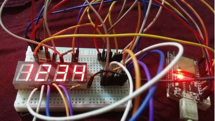
Next type a number in between 0-9999. We have typed ‘1234.’ Then press enter.
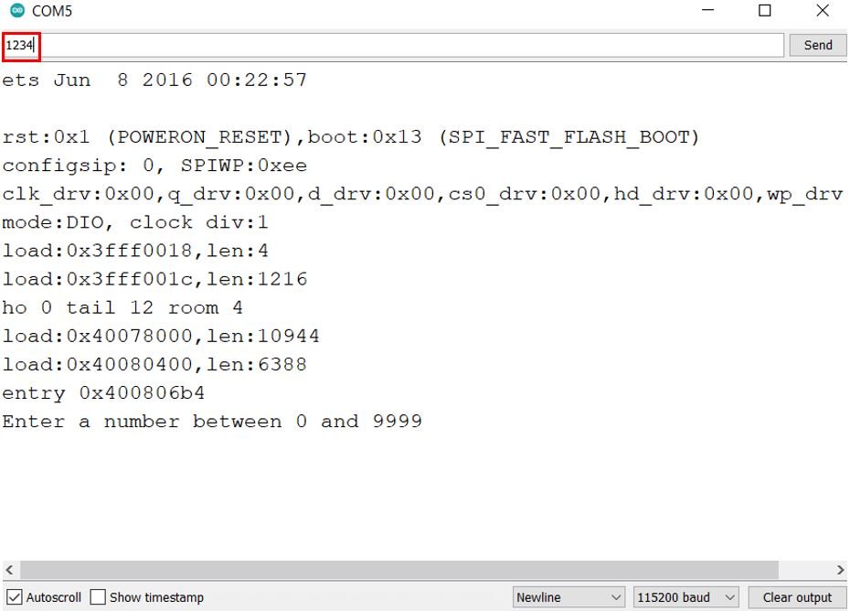
Immediately the 4 digit 7 segment display will display the number.
Video Demo:
For more related articles follow the links below: