In this Arduino tutorial, we will learn to interface touch sensor with Arduino. We will discuss its working, pinout, and programming it with Arduino. A touch sensor/button/switch is a type of switch that is used to monitor touch.
Recommended Components
The following components are used in this project or are helpful for building it with the Arduino.
| Component | How it’s used in this project | Buy on Amazon |
|---|---|---|
| Arduino Uno R3 | Reads the touch sensor’s digital output and drives an LED to demonstrate the response. | Check Price |
| Breadboard | Holds the touch module, LED and resistor for the demonstration circuit. | Check Price |
| Jumper Wires | Connect the touch sensor output and the LED circuit to the Arduino. | Check Price |
| 5mm LED | An LED toggled by the Arduino to visually indicate when the touch sensor is triggered. | Check Price |
| Resistor Kit (220/4.7k) | Provides the current-limiting resistor for the indicator LED. | Check Price |
As an Amazon Associate we earn from qualifying purchases. Prices and availability are accurate as of the date/time indicated and are subject to change.
Touch Sensor Module
The digital Touch sensor module TTP223B is a low priced sensor that is compact and fairly easy to use. It is commonly used to control devices where touch is detected. The diagram below shows the touch sensor widely available in the markets:
In simple ways, it acts as a button and has the same feature. The working principle of this capacitive touch sensor is like a switch. There are two kinds of touch sensors available in the market: capacitive touch sensor and resistive touch sensor.
The resistive touch sensor consists of two conductive and a single non-conductive layers. What happens is that the outside conductive layer and the inner layer get in contact which produces changes in voltage.
However the touch sensor module we are using features a capacitive touch sensor (TTP223B). When pressure is applied to its surface (touch) then the circuit allows the current to flow through it. The change in capacitance is used to detect the touch. It is mad up of an electrode film which is on top of a glass panel. The glass panel has a printed circuit pattern which is conductive in nature.
When pressure is applied to the touch sensor’s surface, the output signal is HIGH otherwise it is LOW. It goes in low power mode if no one touches the sensor for a few seconds.
Some key advantages of using touch sensors are that they were very cost efficient and compact in nature. They do not consume a lot of power and can easily be integrated with microcontrollers to control devices via touch detection. However, it requires proper amount of pressure in order to detect the touch.
Pinout

The touch sensor as you can see in the picture above consists of only three pins. These are the signal, VCC, and GND pins.
The SIG pin is connected with the digital pin of Arduino board. This will be set up as an input. When pressure will be applied at the sensor’s surface, the signal will be 1 or HIGH. Other wise it will be 0 or LOW.
The VCC pin is connected with the power pin of the Arduino. The touch sensor module supports 2.0-5.5V DC power supply. We will connect this pin with Arduino 5V pin.
The GND pin is connected with the GND of the Arduino board.
Interfacing Touch Sensor Module with Arduino
Following components are required:
- Arduino
- Touch Sensor Module
- Connecting Wires
Follow the schematic diagram below:
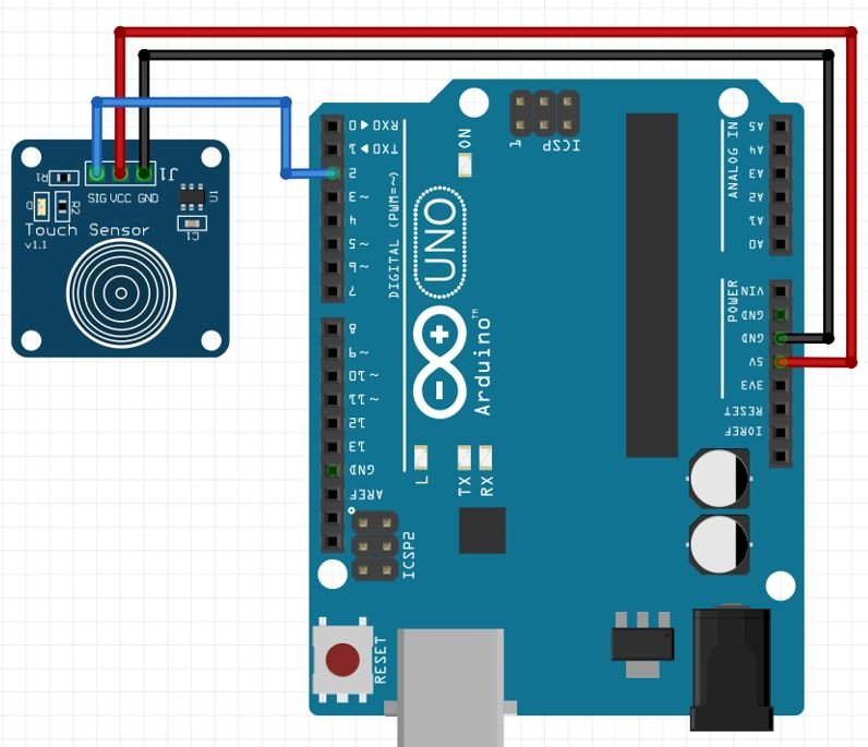
The connections of both the devices are fairly simple. Just connect the SIG pin of the sensor module with any appropriate digital pin of the Arduino board. We have used pin2. Moreover, connect the VCC pin with 5V and connect both the ground pins together to form a successful connection.
Arduino Sketch: Reading signal output from Touch Sensor Module
Open your Arduino IDE and go to File > New to open a new file. Copy the code given below in that file.
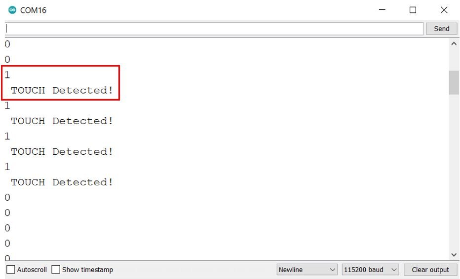
This sketch will display on the serial monitor, the state of the signal pin. Whenever the sensor will be pressed a relevant message will also be displayed.
const int signal_pin = 2;
int state;

void setup() {
  Serial.begin(115200);
  pinMode(signal_pin, INPUT);
}

void loop() {
  state = digitalRead(signal_pin);
  Serial.println(state);
  if(state == HIGH)
  Serial.println(" TOUCH Detected!");
  delay(500);
}
How the Code Works?
First, we will define the touch sensor’s signal pin that we have connected with the Arduino’s digital pin. It is pin2.
const int signal_pin = 2; Then we will define an integer variable that will hold the state of the signal pin.
int state; Inside the setup() function, we will open the serial communication at a baud rate of 115200. Next, we will configure the signal pin as an input pin by using pinMode() function.
void setup() {
  Serial.begin(115200);
  pinMode(signal_pin, INPUT);
}
Inside the loop() function we will first read the state of the touch sensor’s signal pin using digitalRead() function. This value will get saved in the variable ‘state’. This will get printed in the serial monitor. Then we will set an if condition to display “TOUCH Detected!” whenever the state is HIGH.
Remember that the touch sensor signal pin outputs HIGH (1) when pressure is applied to it and outputs LOW (0) when released.
void loop() {
  state = digitalRead(signal_pin);
  Serial.println(state);
  if(state == HIGH)
  Serial.println(" TOUCH Detected!");
  delay(500);
}
Demonstration
Choose the correct board and COM port before uploading your code to the board.
Go to Tools > Board and select Arduino.

Next, go to Tools > Port and select the appropriate port through which your board is connected. Click on the upload button to upload the code into the Arduino development board. After you have uploaded your code to the Arduino press its RST button.
Now open the serial monitor and set the baud rate to 115200. Immediately, the serial monitor starts displaying the signal pin value. Notice that the value is 1 when the touch sensor detects some pressure or basically a ‘touch.’ Otherwise the state is 0.
Control LED using Touch Sensor Module
Now as we have seen how the touch sensor module works let us move a bit further and control an LED using the touch feature. Whenever the Touch sensor’s surface will be pressed the LED will turn ON and when it will be released the LED will turn OFF. This simple project will provide you with an insight into how to control devices using this sensor module. So let us begin.
You will require the following components.
Required Components
- Arduino
- Touch Sensor Module
- One 5mm LED
- One 220 ohm resistor
- Connecting Wires
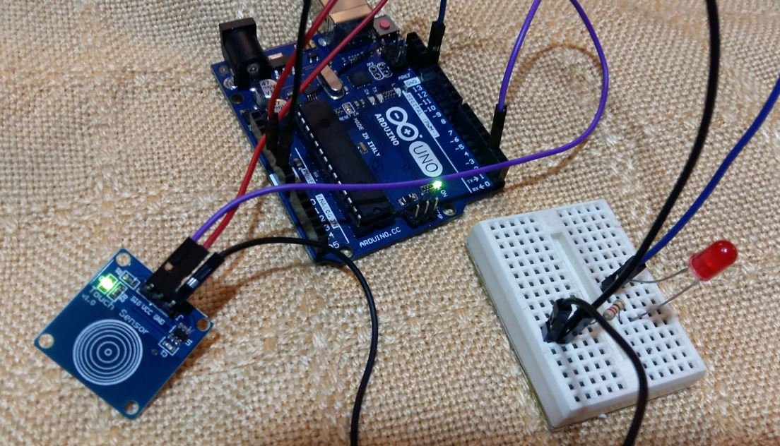
Follow the schematic diagram below, to connect the LED with your Arduino board along with the touch sensor module:
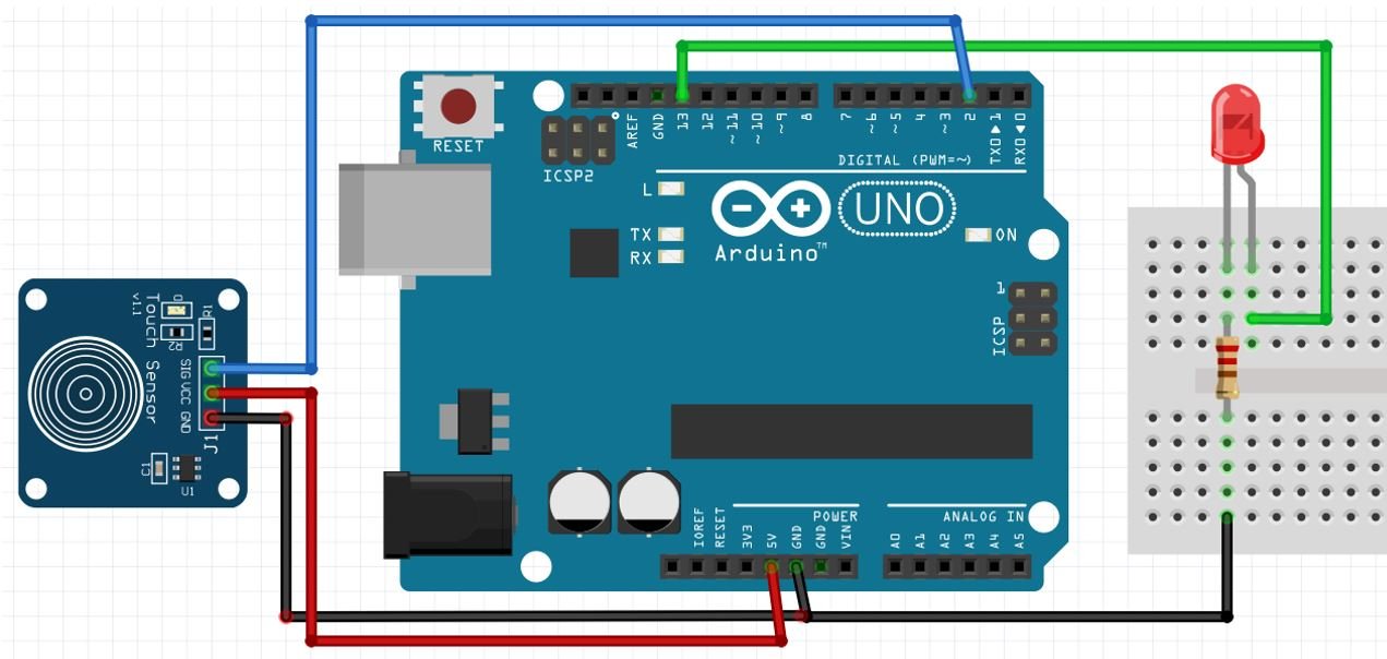
In the above schematic, we can see that GPIO13 is connected with the anode pin of LED, and the cathode pin is connected with the common ground through the 220-ohm resistor. The touch sensor module is connected in the same way as we did previously. Also, make sure all the three devices have a common ground.
Arduino Sketch
Open your Arduino IDE and go to File > New. A new file will open. Copy the code given below in that file and save it.
const int signal_pin = 2;
const int LED_pin = 13;

void setup() {
  Serial.begin(115200);
  pinMode(signal_pin, INPUT);
  pinMode(LED_pin, OUTPUT);
}

void loop() {
  int state = digitalRead(signal_pin);
  digitalWrite(LED_pin, state);
}
How the Code Works?
The first step will be to define the Arduino pins connected with the signal pin of the sensor and the LED.
const int signal_pin = 2;
const int LED_pin = 13;
Then inside the setup() function we will start the serial communication at a baud rate of 115200. Then we will configure the sensor’s signal pin as input pin and the LED pin as the output pin.
void setup() {
  Serial.begin(115200);
  pinMode(signal_pin, INPUT);
  pinMode(LED_pin, OUTPUT);
}
Inside the loop() function we will read the state of the sensor pin using digitalRead() and save it in the ‘state variable. Next we will control the LED using the digitalWrite() function and pass the ‘state’ variable inside it along with the LED pin.
void loop() {
  int state = digitalRead(signal_pin);
  digitalWrite(LED_pin, state);
}
Demonstration
Choose the correct board and COM port before uploading your code to the board.
Go to Tools > Board and select Arduino.
Next, go to Tools > Port and select the appropriate port through which your board is connected. Click on the upload button to upload the code into the Arduino development board. After you have uploaded your code to the Arduino press its RST button.
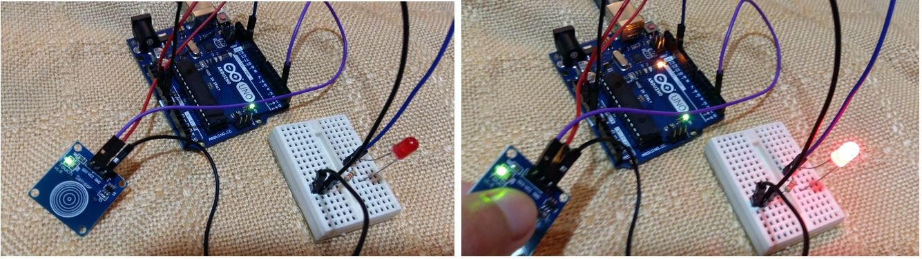
Now touch the sensor module and immediately the LED will turn ON. Then release it and the LED turns OFF.
Video demo:
You may also like to read: