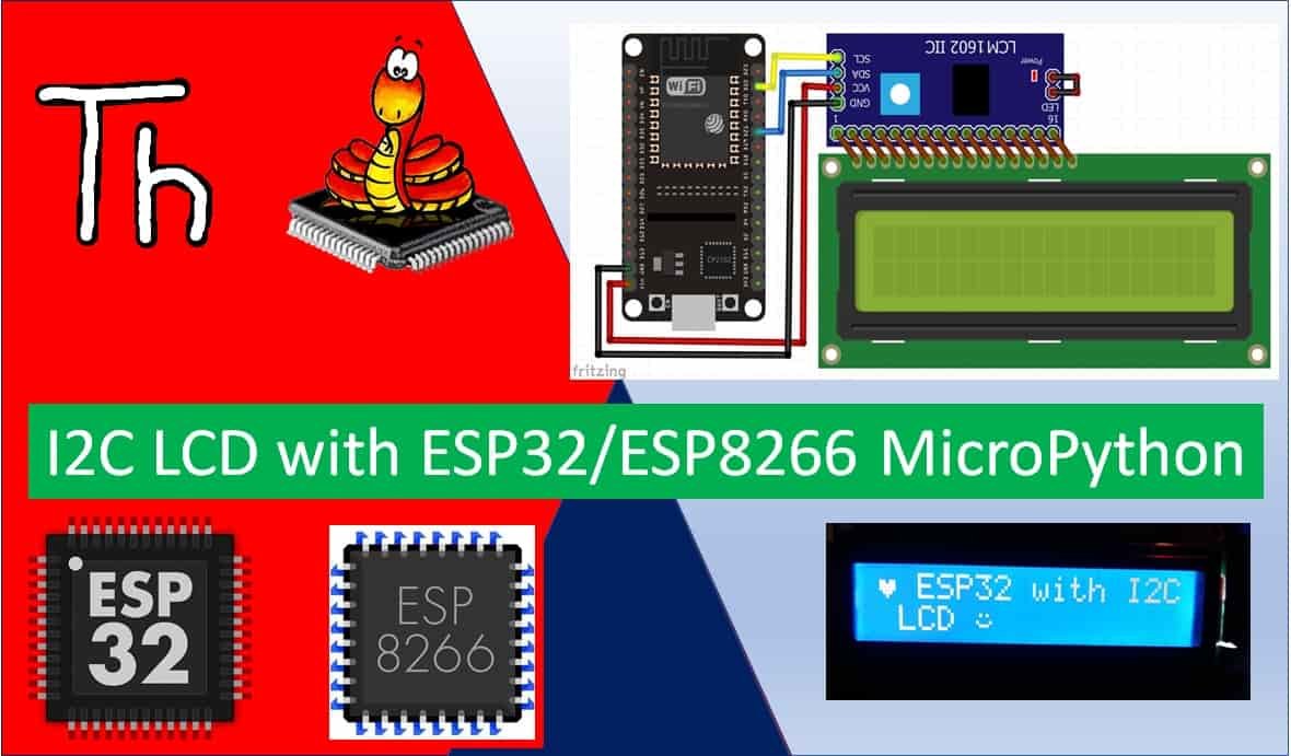
In this tutorial, we will learn how to interface I2C LCD with ESP32/ESP8266 and how to display simple text/numbers and custom characters on I2C LCD. This I2C LCD is a 16×2 device which means it can display 16 columns by two rows of characters. The characters are alphanumeric, but you can create custom characters for basic graphics, bar graphs that kind of thing. The LCD has the usual type of hd44780 controller, and it also has an I2C circuit connected with it which makes it easy to connect to the ESP boards. 16X2 LCD without I2C circuit has sixteen pins.
Recommended Components
The following components are used in this project or are helpful for getting started with MicroPython on ESP32 and ESP8266.
| Component | How it’s used in this project | Buy on Amazon |
|---|---|---|
| ESP32 Development Board (DevKit V1) | The ESP32 board flashed with MicroPython firmware. | Check Price |
| ESP8266 NodeMCU (ESP-12E) | The ESP8266 NodeMCU running the same MicroPython code. | Check Price |
| Micro USB Cable | Programs and powers the board from your PC. | Check Price |
| 16×2 I2C LCD Display | Displays text, numbers, and custom characters in this project. | Check Price |
| Breadboard | Holds the components for prototyping the circuit. | Check Price |
| Jumper Wires | Connects the LCD to the ESP32 or ESP8266. | Check Price |
As an Amazon Associate we earn from qualifying purchases. Prices and availability are accurate as of the date/time indicated and are subject to change.
You can find more information about the pins by going to this article:16×2 Liquid crystal display
But if we want to connect this board directly with the ESP board, we have to use at least eight pins of our board which will be a waste. So the better solution is to use an I2C LCD instead of typical 16×2 LCD. In this tutorial, we are using 16×2 I2C LCD, but LCD of any size will also work the same way as we will learn in this tutorial. The advantage of using an I2C LCD is that we only need to use four pins (including the power pins) of Raspberry Pi Pico to connect with this display.
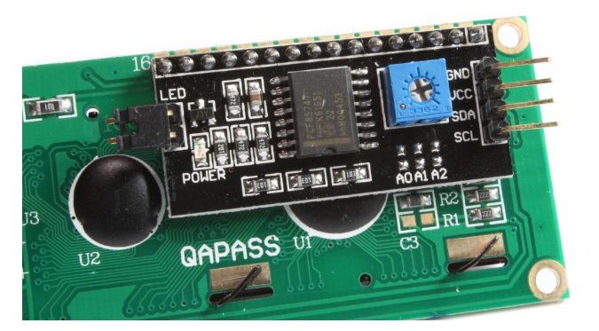
At the backside of this liquid crystal display, you can also see a variable resistor. This variable resistor is used to modify the brightness of the LCD. This potentiometer is very handy when you are using this display module in different light conditions.
Prerequisites
Before we start this lesson make sure you are familiar with and have the latest version of Micro-python firmware installed in your ESP boards and have a running Integrated Development Environment(IDE) in which we will be doing the programming. We will be using Thonny IDE.
If you are using Thonny IDE, you can check this getting started guide:
If using uPyCraft IDE instead, check the getting started articles below:
- Getting Started with MicroPython on ESP32 and ESP8266
- ESP32 and ESP8266 GPIO Programming with MicroPython – LED Blinking Example
I2C LCD Pinout
So now let’s start with the pinout of this display. This display has four pins:
- Ground pin
- Vcc pin
- SDA
- SCL
Now let’s see how to connect this LCD with ESP32 and ESP8266 development boards.
Interfacing I2C LCD with ESP32 and ESP8266
In this section, we will show you how to connect I2C LCD with ESP32 and ESP8266. The I2C LCD will be connected with the ESP board with its 4 pins (GND, VCC, SDA and SCL).
The connection of I2C LCD with the ESP boards is very easy. We have to connect the VCC terminal with Vin pin, ground with the ground (common ground), SCL of the sensor with SCL of the module, and SDA of the sensor with the SDA pin of the ESP modules.
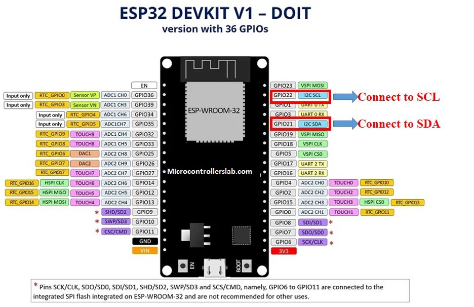
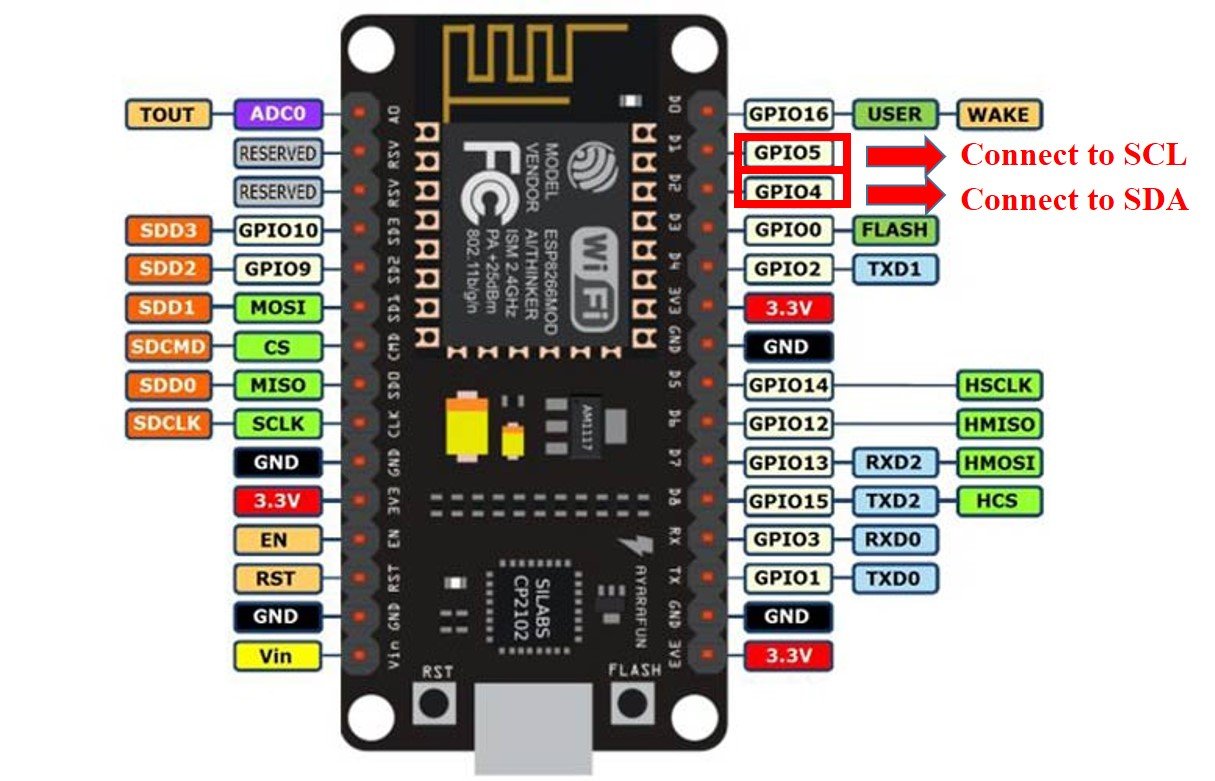
The I2C pin in ESP32 for SDA is GPIO21 and for SCL is GPIO22. Whereas, in ESP8266 the default I2C pins for SDA are GPIO4 and for SCL are GPIO5.
The connections between the devices can be seen below.
| ESP32 | ESP8266 | I2C LCD |
| VCC= Vin | Vin | Vin |
| GPIO21(I2C SDA) | GPIO4 (D2) | SDA |
| GPIO22 (I2C SCL) | GPIO5 (D1) | SCL |
| GROUND | GROUND | GND |
ESP32 I2C Pins
The I2C pins stated above are set in default. If we want to change the GPIO pins we have to set them in code. The diagrams below show the pinout for the ESP32 and Esp8266 respectively.
ESP8266 I2C Pins
The following figure shows the I2C pins of ESP8266 NodeMCU:
More information on ESP32 and ESP8266 pins is available here:
Components Required
We will need the following components to connect our ESP board with the I2C LCD.
- ESP32/ESP8266
- I2C LCD
- Connecting Wires
- Breadboard
Follow the schematic diagrams below for both the ESP modules and connect them accordingly. If you are using ESP32 for this project, connect the ESP32 device with the I2C LCD as shown in the schematic diagram below:

Similarly, you are using ESP8266 NodeMCU for this project, connect the ESP8266 device with the I2C LCD as shown in the schematic diagram below:
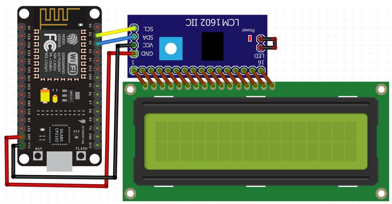
The VCC pin is connected with the Vin pin from the ESP32/ESP8266 to power up. Both the grounds of the two devices are connected in common. The SCL pin of I2C LCD is connected with the default SCL pin of the board. Likewise, the SDA pin is connected with the default SDA pin of the board.
Getting I2C LCD Address
When you connect your I2C display with ESP32/ESP8266, you need to check its address. Because every I2C device has an address associated with it. For many devices of I2C LCD, the default address is 0x27 where 0x shows hex format of the numbers. But address can be different in some cases. This address depends on the position of pads A0, A1, and A2 on the I2C controller on this device.
Now copy this code and upload it your board with the I2C LCD already connected with it.
This code will scan for any I2C devices connected with ESP32 and will specify the number of devices with the address in the shell console. If using ESP8266, replace the SDA and SCL pins appropriately.
import machine

sdaPIN=machine.Pin(21)  #for ESP32
sclPIN=machine.Pin(22)

i2c=machine.I2C(sda=sdaPIN, scl=sclPIN, freq=10000)

devices = i2c.scan()
if len(devices) == 0:
 print("No i2c device !")
else:
 print('i2c devices found:',len(devices))
for device in devices:
 print("At address: ",hex(device))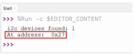
This message shows the address of liquid crystal display is 0x27. You will most likely get the same address for LCD with 16 columns and 2 rows.
I2C LCD MicroPython Libraries
For this project we will require two libraries: lcd_api.py and i2c_lcd.py. Copy both of these libraries and save them in your MicroPython device with the respective file names. Open a new file in Thonny. Copy the libraries from the links given above. Save them to ESP32/ESP8266 with names lcd_api.py and i2c_lcd.py under the lib folder.
MicroPython Display Text/Numbers on I2C LCD
In this section, we will display a message along with numbers on the screen.
import machine
from machine import Pin, SoftI2C
from lcd_api import LcdApi
from i2c_lcd import I2cLcd
from time import sleep

I2C_ADDR = 0x27
totalRows = 2
totalColumns = 16

i2c = SoftI2C(scl=Pin(22), sda=Pin(21), freq=10000)     #initializing the I2C method for ESP32
#i2c = I2C(scl=Pin(5), sda=Pin(4), freq=10000)       #initializing the I2C method for ESP8266

lcd = I2cLcd(i2c, I2C_ADDR, totalRows, totalColumns)

while True:
    lcd.putstr("I2C LCD Tutorial")
    sleep(2)
    lcd.clear()
    lcd.putstr("Lets Count 0-10!")
    sleep(2)
    lcd.clear()
    for i in range(11):
        lcd.putstr(str(i))
        sleep(1)
        lcd.clear()
This code will display the message “I2C LCT Tutorial” for two seconds. The screen will clear. Then another message “Lets Count 0-10!” will be displayed for two seconds. After that, it will clear the LCD and display numbers from 0 to 10 after a delay of 1 second.
How the Code Works?
Now we will see the working of code.
Firstly, we will be importing the SoftI2C and Pin class from the machine module. We also import the sleep module so that we will be able to add a delay in between our messages. Also, import LcdApi from the lcd_api library that we just uploaded to our board and I2clcd from the i2c_lcd library.
import machine
from machine import SoftI2C, Pin
from lcd_api import LcdApi
from i2c_lcd import I2cLcd
from time import sleep
Next specify the address of your I2C LCD device. We ran the sketch given previously and found ours to be 0x27.
Additionally, totalRows and totalColumns specify the number of rows and columns of the display which in our case is 16×2. If you want to use a screen of any other size, you need to need to change the number here accordingly, for example, the 20×4 display.
I2C_ADDR = 0x27
totalRows = 2
totalColumns = 16
i2c object
Now, we initialize the SoftI2C method by giving it three arguments. The first argument specifies the GPIO pin for SCL. This is given as GPIO22 for ESP32 and GPIO5 for ESP8266. The second parameter specifies the GPIO pin for the SDA. This is given as GPIO21 for ESP32 and GPIO4 for ESP8266. Keep in mind, these are the default I2C pins for SCL and SDA which we have used for both the ESP boards respectively. The third parameter specifies the maximum frequency for SCL to be used.
i2c = SoftI2C(scl=Pin(22), sda=Pin(21), freq=10000)     #initializing the I2C method for ESP32
#i2c = I2C(scl=Pin(5), sda=Pin(4), freq=10000)       #initializing the I2C method for ESP8266
lcd object
This line is used to initialize the I2C connection for the library by creating an object ‘lcd’. The first argument to the function I2cLcd() is the i2c object declared previously, the second argument is the address of our I2C LCD. Third and fourth arguments are the size in terms of the number of columns and number of rows.
lcd = I2cLcd(i2c, I2C_ADDR, totalRows, totalColumns)Display Text/Numbers
Next, we run an infinite loop inside which we first display the message “I2C LCD Tutorial” for 2 seconds. Then display “Lets Count 0-10!” for 2 seconds after clearing the screen. Then we clear the screen using the clear() method on the lcd object. After that we use a for loop to display numbers from 0 to 10 after a delay of 1 second each. After each number is displayed, wait for one second, then clear() will erase the text.
while True:
    lcd.putstr("I2C LCD Tutorial")
    sleep(2)
    lcd.clear()
    lcd.putstr("Lets Count 0-10!")
    sleep(2)
    lcd.clear()
    for i in range(11):
        lcd.putstr(str(i))
        sleep(1)
        lcd.clear()
Demonstration
To test this program with ESP32/ESP8266, upload this main.py file to your board. Once the code is uploaded to the board, adjust the brightness of the display through the potentiometer until the LCD starts displaying the messages:
Display Custom Characters on I2C LCD using ESP32/ESP8266 MicroPython
In this section, we will display custom characters on the LCD screen.
For our 16×2 LCD display that we are using, we have the option to display custom characters as well. In this particular LCD, each block consists of 5×8 pixels. These can be used to display custom characters by setting the state of each pixel inside a byte array.
There is a very simple way to generate the byte array of your own custom character. Head over to the following custom character generator: (LCD Custom Character Generator).
The following web page opens up. Select the data type as ‘Hex’.
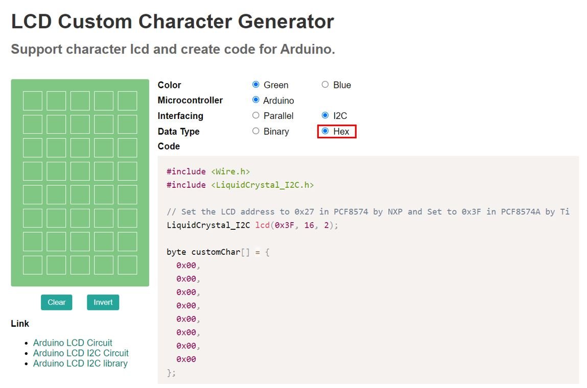
Specify the custom character you want to display by clicking the pixels in the 5×8 pixel block and the corresponding byte variable will be generated.
In our case, we will display a heart character on the screen. We will require the hex data that is highlighted in the red rectangle below to form our byte array. We will use these values inside our byte array while programming the ESP32/ESP8266 to display custom characters.
Likewise, you can generate custom characters according to your preference from this generator and just copy the hex numbers to fill the byte array while programming your board in MicroPython.
Lets look at the MicroPython script to display custom characters on the I2C LCD with ESP32/ESP8266
MicroPython Display custom Character on I2C LCD
import machine
from machine import SoftI2C, Pin
from lcd_api import LcdApi
from i2c_lcd import I2cLcd

I2C_ADDR = 0x27
totalRows = 2
totalColumns = 16

i2c = SoftI2C(scl=Pin(22), sda=Pin(21), freq=10000)     #initializing the I2C method for ESP32
#i2c = I2C(scl=Pin(5), sda=Pin(4), freq=10000)       #initializing the I2C method for ESP8266

lcd = I2cLcd(i2c, I2C_ADDR, totalRows, totalColumns)

heart = bytearray([0x00,0x00,0x1B,0x1F,0x1F,0x0E,0x04,0x00])
face = bytearray([0x00,0x00,0x0A,0x00,0x11,0x0E,0x00,0x00])
lcd.custom_char(0, heart)
lcd.custom_char(1, face)
lcd.putstr(chr(0)+" ESP32 with I2C LCD "+chr(1))
This code displays the message ‘ESP32 with I2C LCD’ in between a heart custom character and a smiley face custom character.
How the Code Works?
Most of the code is similar to the previous sketch. Let us explain the parts where the custom character is involved.
Create a bytearray for a heart with hex values obtained from the LCD Custom Character Generator.
heart = bytearray([0x00,0x00,0x1B,0x1F,0x1F,0x0E,0x04,0x00])Likewise, we also create another bytearray for a smiley face with hex values obtained from the LCD Custom Character Generator.
face = bytearray([0x00,0x00,0x0A,0x00,0x11,0x0E,0x00,0x00])
Next, we will create the custom character by calling lcd.custom_char() and pass a number between 0-7 (allocated location) and the variable containing the bytearray as parameters inside it.
lcd.custom_char(0, heart)
lcd.custom_char(1, face)
We will display the heart character followed by ‘ESP32 with I2C LCD’ followed by the smiley face character on the screen.
lcd.putstr(chr(0)+" ESP32 with I2C LCD "+chr(1))Demonstration
To test this program with ESP32/ESP8266, upload this main.py file to your board. Once the code is uploaded to the board, adjust the brightness of the display through the potentiometer until the LCD starts displaying the message.

You may also like to read:
Anxious to learn micropython!
Bo W4GHV since ’54
how would this look like in the code without i2c? 😉
Thanks for this. Working fine on the ESP32 and a 4 x 20 display – its been a great start for me – much appreciated.
Hello I don’t know why but my ESP32 don’t recognize the i2c_lcd module. Can someone helps me ? Ty