Hitachi HD44780 LCD module
For Display Hitachi HD44780 based character LCD modules are used. LCD interacing have many applications in microcontrollers based projects. The HD44780- based LCD unit can be operated in two modes, 8-bit and 4-bit mode. In 4-bit mode data is send using two four bit nibbles (First high four bits and then low four bits with an E Clock pulse with each nibble). The correct timing of the control signals is generated by software; therefore any AVR with at least seven free I/O pins can be used.Apart from the data-bus, 2 or 3 control-lines are needed, namely RS (Register shift), R/W (Read/Write) and E (Enable).
you may also like to read lcd interfacing with Arduino
Hitachi HD44780 LCD module pinout
RS (Register shift): This pin is used to select whether data or an instruction is being transferred between the microcontroller and the LCD. If the pin is high, then the byte at the current LCD Cursor Position can be read or written. If the pin is low, either an instruction is being sent to the LCD or the execution status of the last instruction is read back (whether or not it has completed).
R/W (Read/Write): It determines the data direction (this pin can be tied to VSS to save an I/O-pin on the controller, but this will make it impossible to read back status from the display, so all data must be sent slow enough to live up to the worst-case delays found in the data- sheet),
E (Enable): The E Clock is used to initiate the data transfer within the LCD. The 8-bit mode is best used when speed is required in an application. This pin needs to be set high before sending any data or instruction. After giving delay and passing the argument, the pin needs to be set low.
When power is applied to the display, it will start in the unitialized state, which is indicated by the top line being all black, while nothing is displayed in the bottom line. If nothing shows up, this could be due to the contrast setting (the voltage applied to V0 – sometimes called Vee) being wrong.
HD44780 LCD module initialization
Now the initialization sequence needs to be sent to the module. If the R/W-line is not connected, it is important to play safe on the timing, to ensure proper initialization. Note that some of the initialization commands take much longer time for the display to process than normal instructions and data. One of the commands sent during the initialization-sequence will configure the display for either 4 or 8-bit mode. The initialization also configures various parameters of the displays behavior, such as if the cursor will be automatically advanced when writing a character, and if the cursor should be shown etc. When the initialization is complete, the black characters in the first line of the display should disappear.
Hitachi HD44780 commands
After initialization, an instruction can be sent to the display, in order to move the cursor to a specific position. For the 2×16 char displays. The first line has character addresses 0x80-0x8F while the second line has 0xC0-0xCF. Third line has addresses 0x90-0x9F and 4th line has 0xD0-0xDF.
Hitachi HD44780 connections
Most HD44780 based LCD’s use a connector with 14 pins in a row. The pins are wired as:
| Pins | Signal | Description |
| 1 | Ground | 0V |
| 2 | Vcc | +5V |
| 3 | Contrast Voltage | |
| 4 | R/S Register Select | 0=Instruction Register. 1=Data |
| 5 | R/W Read/Write LCD | 1=Read from LCD, 0=Write to LCD |
| 6 | E Clock | 450nsecs positive pulse to initiate data transfer |
| 7 – 14 | Data I/O Pins | 8-bit data bus (4-bit mode only uses pins 11..14) |
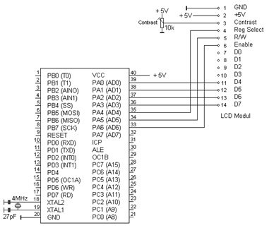
General Interfacing of LCD Module with microcontroller is shown below:
The HD44780 instruction set is shown below:
Set Cursor Move Direction: 00000001IDS
- ID – Increment the Cursor after Each Byte Written to Display if Set
- S – Shift Display when Byte Written to Display Enable Display/Cursor: 0000001DCB
- D – Display On(1)/Off(0)
- C – Cursor On(1)/Off(0)
- B – Cursor Blink On(1)/Off(0) Move Cursor/Shift Display: 00001SCRL
- SC – Display Shift On(1)/Off(0)
- RL – Direction of Shift Right(1)/Left(0) Set Interface Length: 00001DLNF**
- DL – Set Data Interface Length 8(1)/4(0)
- N – Number of Display Lines 1(0)/2(1)
- F – Character Font 5×10(1)/5×7(0)
Poll the “Busy Flag”: 01BF*******
- BF – This bit is set while the LCD is processing
In our project we have used 4-bit mode. In 4-bit mode, the high nibble is sent before the low nibble and the E pin is toggled each time four bits is sent to the LCD.
To initialize in 4-bit mode following commands are used: delayms(15);
lcd cmd(0x03); delayms(5); lcd cmd(0x03); delay ms(1);
lcd_cmd(0x03); delay ms(1); lcd cmd(0x02); delay ms(1);
lcd cmd(0x2C); //Set interface length delay ms(1);
lcd cmd(0x08); // Turn off display delay ms(1);
lcd cmd(0x01); //Clear display delay ms(1);
lcd_cmd(0x06); //Set cursor move direction delay ms(1);
lcd cmd(0x0F); //Enable display cursor delay ms(1);
For sending commands following sequence is used: RS low for command, RW low for write Set enable
Send 0x0F;
Send upper nibble Enable low
Delay ms(1); Set enable Send 0x0F;
Send lower nibble Enable low delayms(1);
How to use this model in proteus software?