In this tutorial, we will learn to use ESP-MESH network using the painlessMesh library and ESP32/ESP8266 NodeMCU. This getting started user guide focuses on ESP-MESH networking protocol by Espressif. This protocol lets numerous ESP boards communicate with each other over a large distance under a sole WLAN. These ESP boards are commonly referred to as nodes. We learn how to create a mesh network using these nodes( ESP32 and ESP8366) and communicate wirelessly using the ESP-MESH networking protocol. We will be using Arduino IDE to program our ESP boards.
By the end of this guide we will show you:
- Introduction to ESP-MESH protocol
- Exchanging simple messages between ESP32/ESP8266 via ESP-MESH
- Exchanging sensor readings between ESP32/ESP8266 via ESP-MESH
Recommended Components
The following components are used in this project or are helpful for building it with the ESP32.
| Component | How it’s used in this project | Buy on Amazon |
|---|---|---|
| ESP32 Development Board (DevKit V1) | The main controller that runs the project code and connects to the components. | Check Price |
| ESP8266 NodeMCU (ESP-12E) | Alternative Wi-Fi board you can use to follow this tutorial with the ESP8266. | Check Price |
| Micro USB Cable | Connects the ESP32 to your computer for programming and power. | Check Price |
| Breadboard | Lets you build the circuit and wire up parts without soldering. | Check Price |
| Jumper Wires | Make the connections between the ESP32 and the components on the breadboard. | Check Price |
As an Amazon Associate we earn from qualifying purchases. Prices and availability are accurate as of the date/time indicated and are subject to change.
ESP-MESH protocol Introduction
ESP-MESH networking protocol allows ESP devices commonly known as nodes spread over a vast area to connect with each and transmit/receive data in an easy and efficient manner. Here the mesh network consists of all the various nodes interconnected with each other and forming a single network. The nodes consist of both the ESP32 and ESP8266 NodeMCU boards.
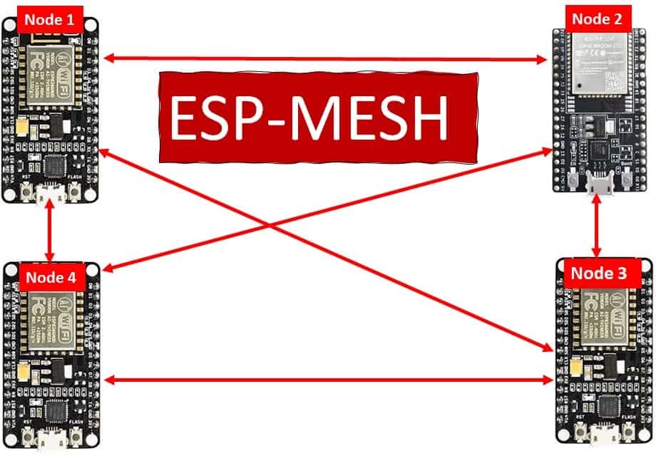
The nodes connect to each other immediately once the ESP-MESH protocol is initiated. As an example a single node can connect with multiple other nodes and transmit messages accordingly. This forms a very orderly process where the message is effectively transmitted to other nodes even if any one of them fails or is removed. This interconnection of nodes does not require a central node thus increasing the number of nodes in the network as well as the coverage area.
ESP-MESH Network Architecture
The following diagram shows the ESP-MESH network architecture that the protocol follows.

As you can see there is a central node (access point) that connects with a single node. In the ESP-MESH network, the other nodes are not required to connect to the central node to relay messages.
This is different as compared to the traditional Wi-Fi network architecture where the central node (access point) is connected with all the stations. This causes a limited coverage area due to the fact that every station has to be connected with the central node. However, in ESP-MESH network this is not the case. Stations outside the range of the access point will also be able to connect with other nodes as there is no need to connect with the central node. Thus, a large number of ESP devices will be able to connect with each other to exchange messages effectively. In case of a failure of a node, the others re-align in such a manner that the interconnectivity stays and the message gets delivered promptly.
ESP-MESH Key Features
Some key features of ESP-MESH networking protocol are given below:
- Low cost network
- Nodes automatically connect with neighbouring nodes to form a mesh network
- Has a data transfer rate of 10Mbps
- The mesh network consumes very less power making it a power efficient choice
- Due to the fact that nodes do not need to connect with the central node, the coverage area exceeds considerably covering almost 1000 nodes per network with a maximum distance of 200m between the neighbouring nodes.
- Has a considerably easy configuration of Bluetooth connection between the smartphones and the mesh network
Setting up Arduino IDE for ESP-MESH
We will use Arduino IDE to program our ESP32/ESP8266 development boards. Thus, you should have the latest version of Arduino IDE. Additionally, you also need to install the ESP32 and the ESP8266 plugin. If your IDE does not have the plugins installed you can visit the links below:
Installing ESP32 library in Arduino IDE and upload code
Installing ESP8266 library in Arduino IDE
Installing painlessMesh Library
We will use the painlessMesh library to construct our Mesh network with ESP32 and ESP8266 boards in a fairly easier way. We will use the Arduino Library Manager to install this library.
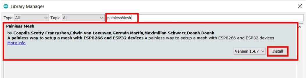
Open your Arduino IDE and go to Sketch > Library > Manage Libraries. Type ‘painlessMesh’ in the search bar and press enter. Install the library that is highlighted below.
Additionally, you will be asked to install all the library dependencies as well. These include:
- ArduinoJson by bblanchon
- TaskScheduler
- ESPAsyncTCP (for ESP8266)
- AsyncTCP (for ESP32)
As we already installed the other libraries except for TaskScheduler previously, hence only it showed as a missing dependency. Click ‘Install all’ to install all the missing dependencies.

ESP32/ESP8266 Exchanging Simple Message using ESP-MESH protocol
Now, let us learn how to exchange simple messages between multiple ESP32/ESP8266 boards. As an example we will use four ESP boards including one ESP8266 NodeMCU and three ESP32 development boards. The ESP8266 board will be assigned as Node 1 and the ESP32 boards will assigned Node 2, Node 3 and Node 4 respectively.

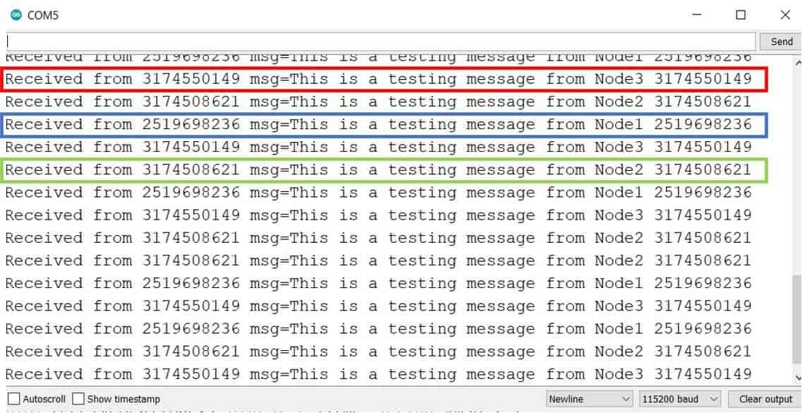
Our aim will be to show you how to exchange a simple message between ESP boards using the ESP-MESH network protocol using the painlessMesh library that we installed previously. The message exchanged will be: ‘This is a testing message from Node X’ where X will specify the number assigned to each board in the program sketch. Node 1 will receive messages from Node 2, Node 3 and Node 4. Likewise, each Node will receive messages from the other node and send its own message to the rest of the nodes.
Arduino Sketch: ESP32/ESP8266 Exchanging Simple Message using ESP-MESH protocol
Open your Arduino IDE and go to File > New to open a new file. Copy the code given below in that file and save it. This sketch works for both ESP32 and ESP8266 development boards.
#include "painlessMesh.h"

#define   MESH_PREFIX     "Mesh_username"
#define   MESH_PASSWORD   "mesh_password"
#define   MESH_PORT       5555

Scheduler userScheduler;
painlessMesh  mesh;

void sendmsg() ;

Task taskSendmsg( TASK_SECOND * 1 , TASK_FOREVER, &sendmsg );

void sendmsg() {
  String msg = "This is a testing message from Node1";
  msg += mesh.getNodeId();
  mesh.sendBroadcast( msg );
  taskSendmsg.setInterval( random( TASK_SECOND * 1, TASK_SECOND * 5 ));
}


void receivedCallback( uint32_t from, String &msg ) {
  Serial.printf("Received from %u msg=%s\n", from, msg.c_str());
}

void newConnectionCallback(uint32_t nodeId) {
    Serial.printf("New Connection, nodeId = %u\n", nodeId);
}

void changedConnectionCallback() {
  Serial.printf("Changed connections\n");
}

void nodeTimeAdjustedCallback(int32_t offset) {
    Serial.printf("Adjusted time %u. Offset = %d\n", mesh.getNodeTime(),offset);
}

void setup() {
  Serial.begin(115200);
  mesh.setDebugMsgTypes( ERROR | STARTUP );

  mesh.init( MESH_PREFIX, MESH_PASSWORD, &userScheduler, MESH_PORT );
  mesh.onReceive(&receivedCallback);
  mesh.onNewConnection(&newConnectionCallback);
  mesh.onChangedConnections(&changedConnectionCallback);
  mesh.onNodeTimeAdjusted(&nodeTimeAdjustedCallback);

  userScheduler.addTask( taskSendmsg );
  taskSendmsg.enable();
}

void loop() {
  mesh.update();
}
How the Code Works?
Firstly, we will include the painlessMesh library that we previously installed. This library will make it easier for us to exchange messages between the ESP boards via the ESP-MESH networking protocol. Our Mesh network will get constructed in a fairly simpler manner through this.
#include "painlessMesh.h"Next, we will define some details for our mesh. These include the mesh name, password and port. You can set the mesh name and password according to your liking. The mesh port will remain 5555 as it is the default port.
#define   MESH_PREFIX     "Mesh_username"
#define   MESH_PASSWORD   "mesh_password"
#define   MESH_PORT       5555
Then, we will create two instances one for the Scheduler and the other for the painlessMesh library. These are named ‘userScheduler’ and ‘mesh’ respectively. The userScheduler will make sure the mesh network stays intact throughout and the mesh object will be used to handle the mesh network accordingly.
Scheduler userScheduler;
painlessMesh  mesh;
Now, we will create a task called taskSendmsg() that takes in three parameters. The first parameter is the time in seconds after which the task will call the function. The second parameter is the duration of the task. The third parameter is the pointer to the calling function. This task will call the sendMessage() function indefinitely after every 1 second.
Task taskSendmsg( TASK_SECOND * 1 , TASK_FOREVER, &sendmsg );Sending Message
The void sendmsg() function will be the one that is responsible for sending the message to all the nodes.
void sendmsg() {
  String msg = "This is a testing message from Node1";
  msg += mesh.getNodeId();
  mesh.sendBroadcast( msg );
  taskSendmsg.setInterval( random( TASK_SECOND * 1, TASK_SECOND * 5 ));
}
The message is saved in the string variable ‘msg.’ For our example, this sketch is for Node 1 so it holds the message “This is a testing message from Node1.” Additionally, the chip ID of the board will also be sent along. This will be obtained by using the getNodeId() on the mesh object.
 String msg = "This is a testing message from Node1";
 msg += mesh.getNodeId();
By using mesh.sendBroadcast() with ‘msg’ as the parameter inside it, the message saved in the ‘msg’ variable will be broadcasted. Moreover, we will also set the interval in seconds between the messages.
 mesh.sendBroadcast( msg );
 taskSendmsg.setInterval( random( TASK_SECOND * 1, TASK_SECOND * 5 ))
Callback functions
The following four functions are the mesh callback functions.
The first function is the receivedCallback() that takes in two parameters. The first parameters is the node ID of the sender and the second parameter is the message pointer (&msg). This function is called whenever a message is received by a node. It prints the message and the sender’s ID in the serial monitor of the receiver board.
The second function is the newConnectcallback() that takes in the node Id of a new node joining the mesh network. Whenever a new node joins the mesh network, this function is called. It prints new connection with its ID in the serial monitor.
The third function is changedConnectionCallback() that takes in no parameters. It is called whenever a node joins or leaves the mesh network.
Lastly, the nodeTimeAdjustedCallback() makes sure that the time is adjusted to keep all the nodes in the mesh network synchronized. The time offset will be printed in the serial monitor.
void receivedCallback( uint32_t from, String &msg ) {
  Serial.printf("Received from %u msg=%s\n", from, msg.c_str());
}

void newConnectionCallback(uint32_t nodeId) {
    Serial.printf("New Connection, nodeId = %u\n", nodeId);
}

void changedConnectionCallback() {
  Serial.printf("Changed connections\n");
}

void nodeTimeAdjustedCallback(int32_t offset) {
    Serial.printf("Adjusted time %u. Offset = %d\n", mesh.getNodeTime(),offset);
}
setup()
Inside the setup() function we will open the serial communication at a baud rate 115200.
Serial.begin(115200);Next, we will set up the debug function for ERROR | STARTUP messages by using setDebugMsgTypes() on the mesh object and passing the debug message type as a parameter inside it. Moreover, we will also initialize the mesh by using init() on the mesh object. This takes in the parameters which we defined earlier including the mesh name, mesh password, userScheduler pointer, and the mesh port.
 mesh.setDebugMsgTypes( ERROR | STARTUP );
 mesh.init( MESH_PREFIX, MESH_PASSWORD, &userScheduler, MESH_PORT );
The next important step is to initialize all the callback functions that we previously defined according to their events. These will be called according to the event occurrence.
  mesh.onReceive(&receivedCallback);
  mesh.onNewConnection(&newConnectionCallback);
  mesh.onChangedConnections(&changedConnectionCallback);
  mesh.onNodeTimeAdjusted(&nodeTimeAdjustedCallback);
Then we will use addTask() on the userScheduler object and pass the taskSendmsg as a parameter inside it. This will add the task to the scheduler which will then be enabled by using taskSendmsg.enable(). This will make sure that all the tasks are handled in a proper and timely manner.
userScheduler.addTask( taskSendmsg );
taskSendmsg.enable();
loop()
Inside the loop() function, we will update the mesh indefinitely so that the mesh network keeps on running.
void loop() {
  mesh.update();
}
Demonstration
Now upload this code onto the respective ESP32/ESP8266 boards. Make sure to change the message contents according to the sender node so that the receiver is able to identify which node sent the particular message. In our case ESP8266 is Node 1 and ESP32 are Node 2, Node 3 and Node 4. Also make sure all the four boards are powered on throughout the demonstration.

Choose the correct board and COM port before uploading your code to the board. Therefore go to Tools > Board and select ESP32 Dev Module or NodeMCU 1.0.
If you are using ESP32, select the ESP32 Dev module as follows:

If you are using ESP8266 NodeMCU, select the NodMCU module as follows:

Then, go to Tools > Port and select the appropriate port through which your board is connected.

Click on the upload button to upload the code to ESP32 or ESP8266 development board.
After you have uploaded your code to the ESP32 or ESP8266 development board, press its ENABLE button.

ESP8266 NodeMCU reset button:

In your Arduino IDE, open up the serial monitor and you will see that the messages received by your board. In our case, we have opened the serial monitor for Node 4 thus it shows messages being received from Node 1, Node 2 and Node 3 along with their chip IDs.
ESP32/ESP8266 Exchanging Sensor Readings using ESP-MESH protocol
After seeing how to exchange simple messages between ESP boards using ESP-MESH network let us move ahead. This time we will exchange sensor readings between multiple ESP32/ESP8266 boards. As an example we will use four ESP boards including one ESP8266 NodeMCU and three ESP32 development boards each connected with a ds18b20 temperature sensor. The ESP8266 board will be assigned as Node 1 and the ESP32 boards will assigned Node 2, Node 3 and Node 4 respectively. Each node will receive temperature readings of the other nodes.

Any preferred sensor, such as BME280, BME680, LM35, and MPU6050, can be used but for this article, we will use a ds18b20 sensor which will be used to measure the ambient temperature. One of the advantages of using this sensor is that we only require a single pin of our ESP boards to transfer data. Thus, it is extremely convenient to use with the micro-controller as we can measure multiple temperatures by using the least number of pins on our development board. The sensor readings will be accessed from the ds18b20 sensor connected with the ESP32/ESP8266 board.
Our aim will be to show you how to exchange these temperature readings between ESP boards using the ESP-MESH network protocol using the painlessMesh library that we installed previously. The message exchanged will be the temperature reading along with the node number and the chip ID of the board. Node 1 will receive temperature readings from Node 2, Node 3 and Node 4. Likewise, each Node will receive temperature readings from the other node and send its own reading to the rest of the nodes.
For this example we will require the following components:
Required Components
- 4x ESP32/ESP8266 boards
- Connecting wires
- 4x ds18b20 sensors
- 4x 4.7k ohm resistors
- Breadboard
ESP32 NodeMCU with DS18B20 Schematic Diagram
If using ESP32, connect the development board and the sensor as shown in the schematic diagram below.
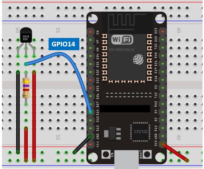
We have powered the sensor using the normal mode. The DS18B20 sensor has three terminals. The first terminal is grounded with the ESP32 board. The data line of the sensor, which is the middle terminal, is connected through GPIO14 through a pull-up resistor of 4.7k-ohm. You can choose any other GPIO pin as well. The third terminal is powered by 3.3V from the ESP32 board.
ESP8266 NodeMCU with DS18B20 Schematic Diagram
If using ESP8266 NodeMCU, connect the development board and the sensor as shown in the schematic diagram below.
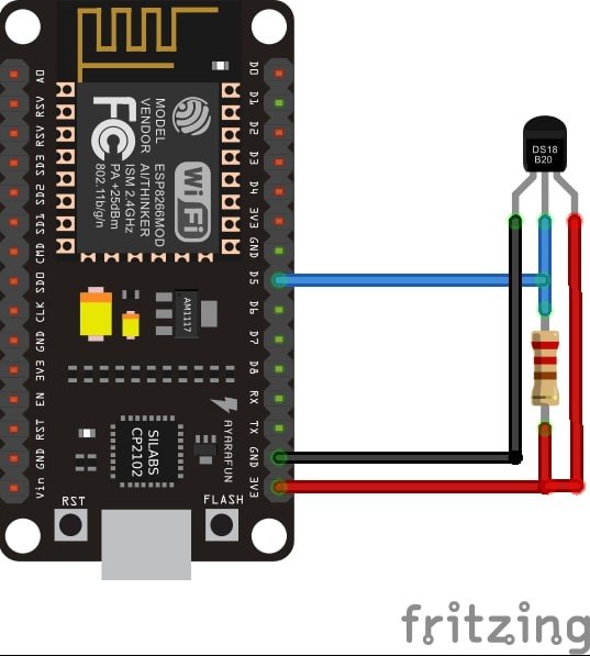
We have powered the sensor using the normal mode. The DS18B20 sensor has three terminals. The first terminal is grounded with the ESP8266 NodeMCU board. The data line of the sensor, which is the middle terminal, is connected through GPIO14 through a pull-up resistor of 4.7k-ohm. You can choose any other GPIO pin as well. The third terminal is powered by 3.3V from the ESP8266 board.
Installing Required Arduino Libraries for exchanging sensor readings using ESP-MESH protocol
To use the Dallas DS18B20 sensor we will have to install two libraries.
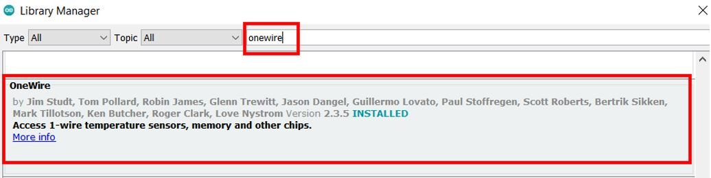
- OneWire library
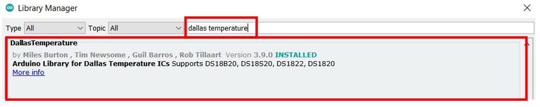
- DallasTemperature library
Follow the steps below to successfully install them. We will use the Library Manager in our Arduino IDE to install the latest versions of the libraries. Open your Arduino IDE and go to Sketch > Include Libraries > Manage Libraries. Type each library name in the search bar and install them both.
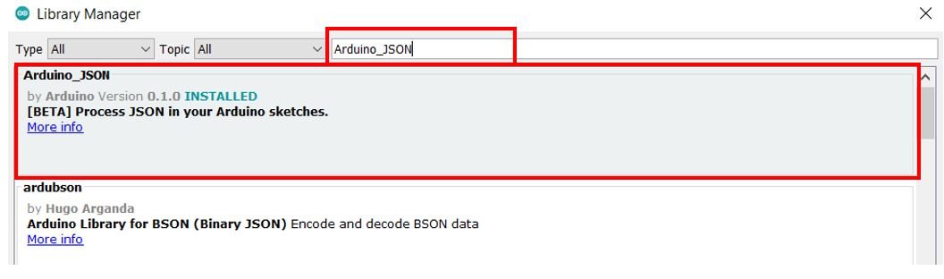
Additionally, we will also require Arduino_JSON library as we will be sending the temperature readings, along with the node ID and chip ID in a JSON string. Follow the same procedure to install it as well. In the Arduino Library Manager type the name ‘Arduino_JSON’ and install it as well.
Arduino Sketch: ESP32/ESP8266 Exchanging Sensor Readings using ESP-MESH protocol
Open your Arduino IDE and go to File > New to open a new file. Copy the code given below in that file and save it. This sketch works for both ESP32 and ESP8266 development boards.
#include <OneWire.h>
#include <DallasTemperature.h>
#include "painlessMesh.h"
#include <Arduino_JSON.h>

#define   MESH_PREFIX     "Mesh_username"
#define   MESH_PASSWORD   "Mesh_password"
#define   MESH_PORT       5555

const int SensorDataPin = 14;
OneWire oneWire(SensorDataPin);
DallasTemperature sensors(&oneWire);

int Node = 1;
String temp_readings;

Scheduler userScheduler;
painlessMesh  mesh;

void sendMessage() ;
String obtain_readings();

Task taskSendMessage(TASK_SECOND * 5 , TASK_FOREVER, &sendMessage);

String obtain_readings () {
  JSONVar jsonReadings;
  sensors.requestTemperatures();
  jsonReadings["Node"] = Node;
  jsonReadings["Temperature"] = sensors.getTempCByIndex(0);
  temp_readings = JSON.stringify(jsonReadings);
  return temp_readings;
}

void sendMessage () {
  String msg = obtain_readings();
  mesh.sendBroadcast(msg);
}

void receivedCallback( uint32_t from, String &msg ) {
  Serial.printf("Received from %u msg=%s\n", from, msg.c_str());
  JSONVar json_object = JSON.parse(msg.c_str());
  int node = json_object["Node"];
  double temp = json_object["Temperature"];
  Serial.print("Node: ");
  Serial.println(node);
  Serial.print("Temperature: ");
  Serial.print(temp);
  Serial.println(" C");
}

void newConnectionCallback(uint32_t nodeId) {
  Serial.printf("New Connection, nodeId = %u\n", nodeId);
}

void changedConnectionCallback() {
  Serial.printf("Changed connections\n");
}

void nodeTimeAdjustedCallback(int32_t offset) {
  Serial.printf("Adjusted time %u. Offset = %d\n", mesh.getNodeTime(),offset);
}

void setup() {
  Serial.begin(115200);
  sensors.begin();

  mesh.setDebugMsgTypes( ERROR | STARTUP );
  mesh.init( MESH_PREFIX, MESH_PASSWORD, &userScheduler, MESH_PORT );
  mesh.onReceive(&receivedCallback);
  mesh.onNewConnection(&newConnectionCallback);
  mesh.onChangedConnections(&changedConnectionCallback);
  mesh.onNodeTimeAdjusted(&nodeTimeAdjustedCallback);

  userScheduler.addTask(taskSendMessage);
  taskSendMessage.enable();
}

void loop() {
  mesh.update();
}
How the Code Works?
Including Libraries
Firstly, we will include the necessary libraries required for this example. The painlessMesh library will make it easier for us to exchange sensor readings between the ESP boards via the ESP-MESH networking protocol. Our Mesh network will get constructed in a fairly simpler manner through this. Additionally, we will include the libraries that we previously installed for ds18b20 sensor functionality and Arduino_JSON to handle the JSON strings.
#include <OneWire.h>
#include <DallasTemperature.h>
#include "painlessMesh.h"
#include <Arduino_JSON.h>
Defining Mesh Details
Secondly, we will define some details for our mesh. These include the mesh name, password and port. You can set the mesh name and password according to your liking. For the mesh port we are using the default port that is 5555.
#define   MESH_PREFIX     "Mesh_username"
#define   MESH_PASSWORD   "Mesh_password"
#define   MESH_PORT       5555
Setting Sensor Parameters
Then, we will create a variable to store the GPIO pin through which the sensor’s data pin is connected. It is called ‘SensorDataPin.’ In our case it is GPIO14. You can use any appropriate GPIO pin.
const int SensorDataPin = 14;We will require the following instances to access the temperature readings. First, we will create a oneWire instance and use the SensorDataPin as an argument inside it. Then we will call the DallasTemperature sensor and pass the oneWire reference which we created above as an argument inside it.
OneWire oneWire(SensorDataPin);
DallasTemperature sensors(&oneWire);
Defining Variables
Now, we will define an integer variable called ‘Node.’ This will hold the node ID (1, 2, 3 or 4). In our case, this sketch is for Node 1 hence the Node is set to 1.
int Node = 1;
We will also define a string variable called ‘temp_readings’ that will save the current temperature readings acquired from the ds18b20 sensor.
String temp_readings;Declaring Instances
Then, we will create two instances one for the Scheduler and the other for the painlessMesh library. These are named ‘userScheduler’ and ‘mesh’ respectively. The userScheduler will make sure the mesh network stays intact throughout and the mesh object will be used to handle the mesh network accordingly.
Scheduler userScheduler;
painlessMesh  mesh;
Now, we will create a task called taskSendmsg() that takes in three parameters. The first parameter is the time in seconds after which the task will call the function. The second parameter is the duration of the task. The third parameter is the pointer to the calling function. This task will call the sendMessage() function indefinitely after every 5 seconds.
Task taskSendMessage(TASK_SECOND * 5 , TASK_FOREVER, &sendMessage);obtain_readings()
The obtain_readings() function is responsible to acquire the temperature reading from the ds18b20 sensor and store it in a JSON variable.
String obtain_readings () {
  JSONVar jsonReadings;
  sensors.requestTemperatures();
  jsonReadings["Node"] = Node;
  jsonReadings["Temperature"] = sensors.getTempCByIndex(0);
  temp_readings = JSON.stringify(jsonReadings);
  return temp_readings;
}
We will first create a JSON variable called ‘jsonReadings.’ To obtain the temperature reading we will first call the requestTemperatures() method. Then we will use the getTempCByIndex() function to retrieve the temperature in degree Celsius. Notice that we are passing 0 as a parameter inside the function. This is because we are using a single ds18b20 sensor connected with each board. This temperature reading along with the node ID (1,2,3 or 4) gets linked together in the JSON variable ‘jsonReadings.’
  JSONVar jsonReadings;
  sensors.requestTemperatures();
  jsonReadings["Node"] = Node;
  jsonReadings["Temperature"] = sensors.getTempCByIndex(0);
Additionally, the JSON variable is then changed into a string using JSON.stringify() and passing jsonReadings as a parameter inside it. This string is saved in the variable ‘temp_readings’ that we initially defined at the start of the sketch. The temp_readings string is thus, returned whenever the obtain_readings() function will be called.
  temp_readings = JSON.stringify(jsonReadings);
  return temp_readings;
sendMessage()
The void sendMessage() function will be the one that is responsible for sending the message to all the nodes. In our case the message is saved in the string variable ‘msg’ that calls the obtain_readings() function. This msg is then broadcasted to all the nodes in the mesh network.
void sendMessage () {
  String msg = obtain_readings();
  mesh.sendBroadcast(msg);
}
Callback Functions
Next up is the receivedCallback() function that takes in two parameters. The first parameter is the node ID (1,2,3 or 4) of the sender and the second parameter is the message pointer (&msg). This function is called whenever a message is received by a node. It prints the message and the sender’s ID in the serial monitor of the receiver board.
void receivedCallback( uint32_t from, String &msg ) {
  Serial.printf("Received from %u msg=%s\n", from, msg.c_str());
  JSONVar json_object = JSON.parse(msg.c_str());
  int node = json_object["Node"];
  double temp = json_object["Temperature"];
  Serial.print("Node: ");
  Serial.println(node);
  Serial.print("Temperature: ");
  Serial.print(temp);
  Serial.println(" C");
}
You can also view the other callback functions below.
The second calback function is the newConnectcallback() that takes in the node Id of a new node joining the mesh network. Whenever a new node joins the mesh network, this function is called. It prints new connection with its ID in the serial monitor.
The third function is changedConnectionCallback() that takes in no parameters. It is called whenever a node joins or leaves the mesh network.
Lastly, the nodeTimeAdjustedCallback() makes sure that the time is adjusted to keep all the nodes in the mesh network synchronized. The time offset will be printed in the serial monitor.
void newConnectionCallback(uint32_t nodeId) {
  Serial.printf("New Connection, nodeId = %u\n", nodeId);
}

void changedConnectionCallback() {
  Serial.printf("Changed connections\n");
}

void nodeTimeAdjustedCallback(int32_t offset) {
  Serial.printf("Adjusted time %u. Offset = %d\n", mesh.getNodeTime(),offset);
}
setup()
Inside the setup() function, we will open a serial connection at a baud rate of 115200. Moreover, we will call sensors.begin() to initialize the ds18b20 sensor as well.
Serial.begin(115200);
sensors.begin();
Next, we will set up the debug function for ERROR | STARTUP messages by using setDebugMsgTypes() on the mesh object and passing the debug message type as parameter inside it. Moreover, we will also initialize the mesh by using init() on the mesh object. This takes in the parameters which we defined earlier including the mesh name, mesh password, userScheduler pointer and the mesh port.
  mesh.setDebugMsgTypes( ERROR | STARTUP );
  mesh.init( MESH_PREFIX, MESH_PASSWORD, &userScheduler, MESH_PORT );
The next important step is to initialize all the callback functions that we previously defined according to their events. These will be called according to the event occurrence.
  mesh.onReceive(&receivedCallback);
  mesh.onNewConnection(&newConnectionCallback);
  mesh.onChangedConnections(&changedConnectionCallback);
  mesh.onNodeTimeAdjusted(&nodeTimeAdjustedCallback);
Then we will use addTask() on the userScheduler object and pass the taskSendmsg as a parameter inside it. This will add the task to the scheduler which will then be enabled by using taskSendmsg.enable(). This will make sure that all the tasks are handled in a proper and timely manner.
userScheduler.addTask(taskSendMessage);
taskSendMessage.enable();
loop()
Inside the loop() function, we will update the mesh indefinitely so that the mesh network keeps on running.
void loop() {
  mesh.update();
}
Demonstration
Now upload this code onto the respective ESP32/ESP8266 boards. Make sure to change the integer variable ‘Node’ according to the sender node ID so that the receiver is able to identify which node sent the particular message. In our case ESP8266 is Node 1 and ESP32 are Node 2, Node 3 and Node 4. Also make sure all the four boards are powered on throughout the demonstration.

Choose the correct board and COM port before uploading your code to the board. Therefore go to Tools > Board and select ESP32 Dev Module or NodeMCU 1.0.
If you are using ESP32, select the ESP32 Dev module as follows:
If you are using ESP8266 NodeMCU, select the NodMCU module as follows:
Then, go to Tools > Port and select the appropriate port through which your board is connected.
Click on the upload button to upload the code to ESP32 or ESP8266 development board.
After you have uploaded your code to the ESP32 or ESP8266 development board, press its ENABLE button.
ESP8266 NodeMCU reset button:
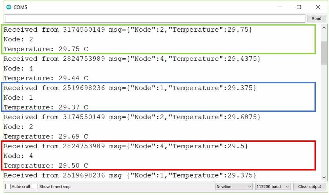
In your Arduino IDE, open up the serial monitor and you will see that the messages received by your board. In our case, we have opened the serial monitor for Node 3 thus it shows the temperature readings being received from Node 1, Node 2 and Node 4 along with their chip IDs.
Conclusion
In conclusion, we have learned about the ESP-MESH networking protocol for ESP32 and ESP8266 NodeMCU development boards using Arduino IDE. To ensure an easier approach, we used the painlessMesh library to create and handle the mesh network properly. In this guide, we had a look at two Arduino sketches. For the first one, we exchanged a simple message between the ESP boards using the ESP-MESH protocol. In the second sketch, we connected ESP boards with the ds18b20 temperature sensor and exchanged temperature readings between the ESP boards.
You may also like to read:
- ESP32 ESP-NOW Getting Started Tutorial with Arduino IDE
- ESP32 ESP-NOW Two way Communication (Arduino IDE)
- ESP32 ESP-NOW Send Data to Multiple boards (One to Many Communication)
- ESP32 ESP-NOW Receive Data from Multiple boards (Many to One Communication)
- ESP32 ESP-NOW and Wi-Fi Web Server using Arduino IDE
Wonderful tutorial. Many thanks.
please do a mesh network for wifi repeaters using wemos d1 or any esp boards
so can connect to a router wifi
Is this esp-mesh protocol based on ESP-now protocol? and if no! which protocol is used?
I want to use the painless mesh protocol but using LORA modules and increase the communication range, do you have information related to this?
Thanks for the detail info.
I added OLED(SSD1306) in the above project.
The OLED is not working. there seems to be a conflict with the painless mesh function.
I tested ESP8266 on the Wemos D1 board.