In this tutorial, we will see how to send data from multiple ESP32 boards to a single ESP32 using ESP-NOW and Arduino IDE. In other words, we will transmit data from many ESP32 to one ESP32 board (Many to One Communication). Previously, we sent data from one ESP32 to another ESP32 and from one ESP32 to many ESP32 boards (One to Many Communication) via ESP NOW one way communication. Additionally, we also transmitted sensor readings between two ESP32 boards and displayed the readings on an OLED display via ESP-NOW two-way communication.
You can access both of the user guides below:
- ESP32 ESP-NOW Getting Started Tutorial with Arduino IDE
- ESP32 ESP-NOW Two way Communication (Arduino IDE)
- ESP-NOW ESP32 Send Data to Multiple boards (One to Many Communication)
Recommended Components
The following components are used in this project or are helpful for building it with the ESP32.
| Component | How it’s used in this project | Buy on Amazon |
|---|---|---|
| ESP32 Development Board (DevKit V1) | The main controller that runs the project code and connects to the components. | Check Price |
| Micro USB Cable | Connects the ESP32 to your computer for programming and power. | Check Price |
| Breadboard | Lets you build the circuit and wire up parts without soldering. | Check Price |
| Jumper Wires | Make the connections between the ESP32 and the components on the breadboard. | Check Price |
As an Amazon Associate we earn from qualifying purchases. Prices and availability are accurate as of the date/time indicated and are subject to change.
ESP-NOW Protocol Introduction
This protocol is a low-power, secure, and direct wireless communication protocol that enables multiple ESP32 devices to communicate with each other without the need for Wi-Fi or a router. Using ESP-NOW, we can perform one-way and even two-way communication between ESP MCU devices without using a Wi-Fi network.
- It allows low overhead peer-to-peer wireless data transfers but in small packets. A maximum of 250 bytes of data can be transferred. Thus if a larger amount of data needs to be transferred then using this protocol is not useful.
- Using ESP-NOW, the connection protocol is simplified which results in low power consumption as a lesser amount of time is required for the transmission of data.
- Additionally, the ESP-NOW uses the same 2.4 GHz band as the Wi-Fi but does not need to connect or interfere with the local network connection.
It is a fast and convenient communication protocol for the transmission of a smaller amount of data.
ESP32 ESP-NOW one-way communication
In one-way communication, one peered device acts as the sender/master and the other as the receiver/slave. We can have multiple configurations of the sender-receiver in this situation.
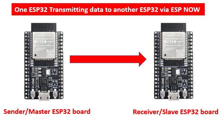
- One ESP32 board sends data to another ESP32 board
As you can view in the picture below, one ESP32 board act as the sender and the other board receives the data and hence acts as the receiver.
Uses: Sending sensor data, controlling ESP outputs including LEDs, relays, buzzers, etc.
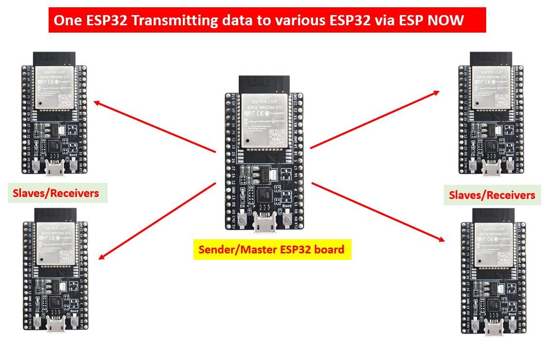
- One ESP32 sender board sends data to various other ESP32 receiver boards
In this scenario, one ESP32 board will act as the sender/master and send data to multiple ESP32 boards that will act as receivers/slaves.
Uses: remote control
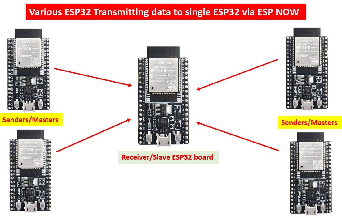
- One ESP32 board receives data from various other ESP32 sender boards
Lastly, in this case, one ESP32 board (receiver/slave) receives data from multiple ESP32 boards (senders/masters).
Uses: Receiving sensor data from various sensors.
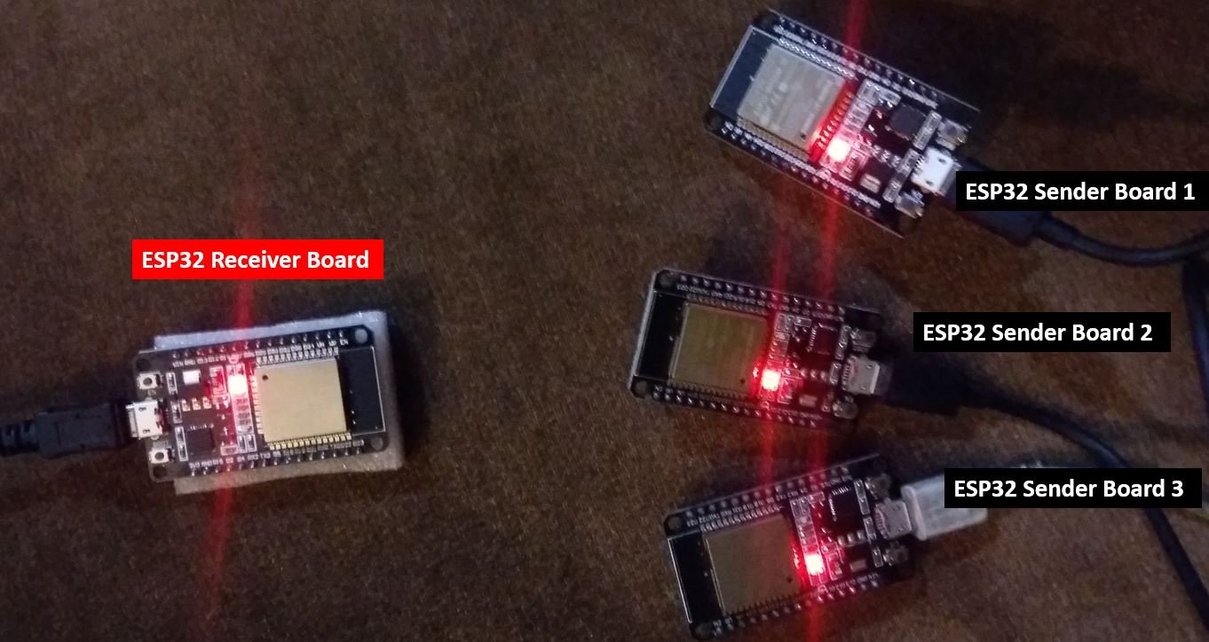
ESP-NOW Many to One Communication Project Overview
This project consists of four ESP32 boards where one will act as the receiver (slave) and the other three will be the senders(masters). Our aim will be to show you how to receive data from the three sender ESP32 boards by the receiver ESP32 board. First, we will find the MAC address of of the receiver ESP32 board. Then, after programming the boards with their respective sender and receiver sketches, receiver board will start receiving data from the sender ESP32 boards through ESP-NOW protocol.
To identify each sender board on the receiver side we will associate an ID for each sender board. For example, the first sender board will have ID=1, the second sender board will have ID=2 and the third sender board will have ID=3. For testing purposes we will send a random integer from 0-20 with the respective ID of the sender board.
You can also use the sketches to transmit useful information between ESP32 devices including sensor data.

Required Hardware:
4x ESP32 development boards
4x power cables
Setting up Arduino IDE
We will use Arduino IDE to program our ESP32 development board. Thus, you should have the latest version of Arduino IDE. Additionally, you also need to install the ESP32 plugin. If your IDE does not have the plugin installed you can visit the link below:
Now, first, we will introduce you to an Arduino sketch which will help us to identify our ESP32 board so that we know exactly which board to transmit the data to. It will display our ESP32 module’s MAC address on the serial monitor which we will later use in another sketch.
Arduino Sketch for obtaining the MAC Address for the receiver ESP32 board
Open your Arduino IDE and go to File > New to open a new file. Copy the code given below in that file and save it.
#include <WiFi.h>

void setup(){
  Serial.begin(115200);
  Serial.println();

  Serial.println(WiFi.macAddress());
}

void loop(){

}
In the setup() function, we are first setting our ESP32 board in station mode. Then by using the WiFi.macAddress() method we will obtain the unique MAC address in our serial monitor.
Make sure you choose the correct board and COM port before uploading your code to the board. Go to Tools > Board and select your board. Next, go to Tools > Port and select the appropriate port through which your board is connected. In this case, we are using the ESP32 development board which is connected to COM5.
Click on the upload button to upload the code into the ESP32 development board. Press its ENABLE button after the sketch has been uploaded.

In your Arduino IDE, open up the serial monitor and you will be able to see the unique MAC address of your ESP32 module.
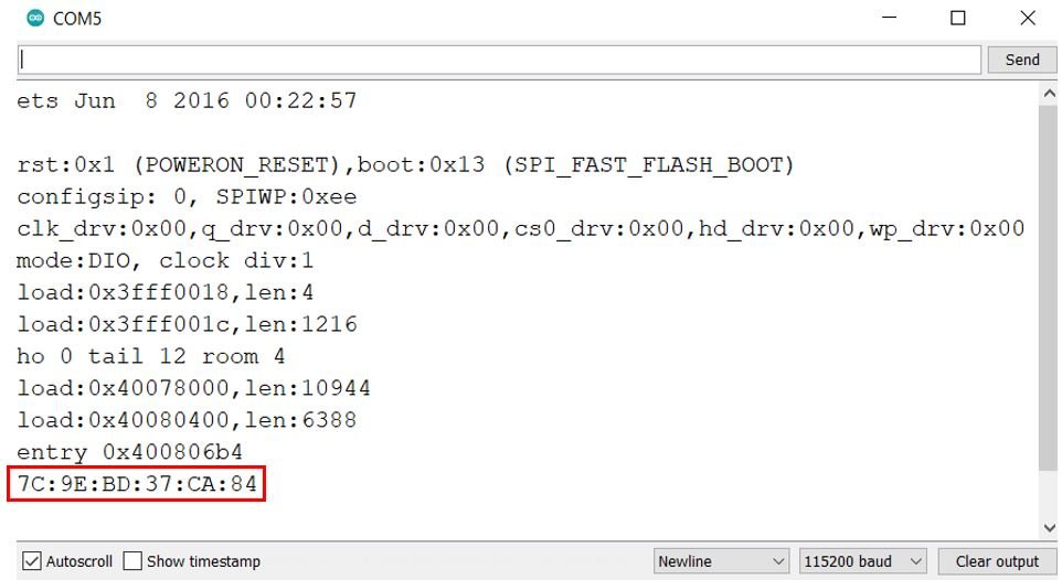
Obtain the MAC address for your receiver ESP32 board and label it. We will need the unique MAC address of the receiver board while programming the sender ESP32 boards.
ESP-NOW ESP32 (Many to one) Arduino Sketches
Now, let us learn how to send data from many ESP32 boards to a single ESP32, using the ESP-NOW protocol. We will use the many-to-one configuration, where multiple ESP32 boards act as the sender and one ESP32 board acts as a receiver. You can use the method given below to transmit sensor data or any type of information from one ESP board to another. For this project, we will require two Arduino sketches one for the senders and the other for the receiver.
ESP-NOW ESP32 Arduino Sketch for Sender Sides
Open your Arduino IDE and go to File > New to open a new file. Copy the code given below in that file and save it. This sketch follows the points given below:
- Firstly, we will initialize ESP NOW by using esp_now_init() function.
- Then we will create a callback function called data_sent() and register it as a callback function using esp_now_register_send_cb() . This will return a message in the serial monitor showing whether the data was transmitted successfully or not.
- The next step will be to add the receiver ESP32 board by using its unique MAC address.
- We will then send the data to this peer device that we set up.
#include <esp_now.h>
#include <WiFi.h>

uint8_t broadcastAddress[] = {0x7C, 0x9E, 0xBD, 0x37, 0xCA, 0x84};

typedef struct struct_message {
    int ID;
    int integer;
} struct_message;

struct_message message;

void data_sent(const uint8_t *mac_addr, esp_now_send_status_t status) {
  Serial.print("\r\n Last Send Status:\t");
  Serial.println(status == ESP_NOW_SEND_SUCCESS ? "Delivery Success" : "Delivery Fail");
}

void setup() {
  Serial.begin(115200);
  WiFi.mode(WIFI_STA);

  if (esp_now_init() != ESP_OK) {
    Serial.println("Error initializing ESP-NOW");
    return;
  }

  esp_now_register_send_cb(data_sent);

  esp_now_peer_info_t peerInfo;
  memcpy(peerInfo.peer_addr, broadcastAddress, 6);
  peerInfo.channel = 0;
  peerInfo.encrypt = false;

  if (esp_now_add_peer(&peerInfo) != ESP_OK){
    Serial.println("Failed to add peer");
    return;
  }
}

void loop() {

  message.ID = 1;
  message.integer = random(0,20);

  esp_err_t outcome = esp_now_send(broadcastAddress, (uint8_t *) &message, sizeof(message));

  if (outcome == ESP_OK) {
    Serial.println("Sent with success");
  }
  else {
    Serial.println("Error sending the data");
  }
  delay(10000);
}
How the Code Works?
Including Libraries
Firstly, we will include the necessary libraries. For the sender sketch, we are using two of them. These include esp_now.h for the ESP-NOW communication protocol and WiFi.h will allow our ESP32 board to use the Wi-Fi functionalities.
#include <esp_now.h>
#include <WiFi.h>
Specifying Receiver MAC Address
Secondly, we will specify the MAC Address of the ESP32 board which will act as the receiver. We will use the same ESP32 board which we used in the sketch above when finding the MAC address. Replace the address with the unique MAC address of your own ESP32 board. You can use the sketch which was given previously, to find the MAC address of your module.
// REPLACE WITH YOUR RECEIVER MAC Address

uint8_t broadcastAddress[] = {0x7C, 0x9E, 0xBD, 0x37, 0xCA, 0x84};
Defining structure for sending data
Now, we will define a structure named ‘struct_message.’ Inside the structure, we will initialize the variables which will hold our data that we will transmit to the receiver board via ESP-NOW. These will be of type int.
typedef struct struct_message {
    int ID;
    int integer;
} struct_message;
Next, we will create a new variable of type struct_message and call it message. This will be used later on in the sketch to acquire the data and transmit it accordingly.
struct_message message;data_sent()
The data_sent() function acts as the callback function which we will define now. It will be used as a parameter when we will register this callback function for sending messages. This prints whether the message was successfully delivered or not on the serial monitor whenever a message will be sent from the ESP32 sender side.
void data_sent(const uint8_t *mac_addr, esp_now_send_status_t status) {
  Serial.print("\r\n Last Send Status:\t");
  Serial.println(status == ESP_NOW_SEND_SUCCESS ? "Delivery Success" : "Delivery Fail");
}
setup()
Inside the setup() function, we will open a serial connection at a baud rate of 115200 and set up the ESP32 board in station mode.
 Serial.begin(115200);
 WiFi.mode(WIFI_STA);
The following lines of code will initialize the ESP-NOW protocol. In case of an unsuccessful connection, the serial monitor will display ‘Error initializing ESP-NOW.’
if (esp_now_init() != ESP_OK) {
    Serial.println("Error initializing ESP-NOW");
    return;
  }
Now we will register the data_sent() function as the callback function. This will make sure that whenever a message will be sent from the sender side, the data_sent() function will be called.
esp_now_register_send_cb(data_sent);The following lines of code will pair the sender and receiver ESP32 boards.
 esp_now_peer_info_t peerInfo;
  memcpy(peerInfo.peer_addr, broadcastAddress, 6);
  peerInfo.channel = 0;
  peerInfo.encrypt = false;

  if (esp_now_add_peer(&peerInfo) != ESP_OK){
    Serial.println("Failed to add peer");
    return;
  }
loop()
Inside the loop() function, we will transmit the message to the receiver ESP32 board. After every 10 seconds, a random integer between 0-20 along with the sender ID will be sent to the receiver side.
You can easily change the structure ‘message’ to send data according to your needs.
As this sketch is for ESP32 sender board #1 hence the message.ID is set to 1. Make sure to change the ID (1,2 or 3) accordingly when you upload this sketch to all three sender boards.
 message.ID = 1;
 message.integer = random(0,20);
Then we will send the message and monitor if it was sent successfully or not.
esp_err_t outcome = esp_now_send(broadcastAddress, (uint8_t *) &message, sizeof(message));

  if (outcome == ESP_OK) {
    Serial.println("Sent with success");
  }
  else {
    Serial.println("Error sending the data");
  }
  delay(10000);
ESP-NOW ESP32 Arduino Sketch for Receiver Side
Open your Arduino IDE and go to File > New to open a new file. Copy the code given below in that file and save it. This sketch follows the points given below:
- Again we will first initialize ESP NOW by using esp_now_init() function.
- Then, we will create another function called data_receive() and register it as a callback function using esp_now_register_rcv_cb(). This callback function will be called whenever the data will be received by the receiver ESP32 board.
#include <esp_now.h>
#include <WiFi.h>

typedef struct struct_message {
  int ID;
  int integer;
}struct_message;

struct_message message;
struct_message sender1;
struct_message sender2;
struct_message sender3;

struct_message boardsStruct[3] = {sender1, sender2, sender3};

void data_receive(const uint8_t * mac_addr, const uint8_t *incomingData, int len) {
  char macStr[18];
  Serial.print("Received from: ");
  snprintf(macStr, sizeof(macStr), "%02x:%02x:%02x:%02x:%02x:%02x",
           mac_addr[0], mac_addr[1], mac_addr[2], mac_addr[3], mac_addr[4], mac_addr[5]);
  Serial.println(macStr);
  memcpy(&message, incomingData, sizeof(message));
  Serial.printf("Board %u: %u bytes\n", message.ID, len);

  boardsStruct[message.ID-1].integer = message.integer;

  Serial.printf("Integer: %d \n", boardsStruct[message.ID-1].integer);
  Serial.println();
}

void setup() {

  Serial.begin(115200);
  WiFi.mode(WIFI_STA);

  if (esp_now_init() != ESP_OK) {
    Serial.println("Error initializing ESP-NOW");
    return;
  }

  esp_now_register_recv_cb(data_receive);
}

void loop() {
}
How the Code Works?
Including Libraries
Firstly, we will include the necessary libraries. For the receiver sketch, we are also using the same two libraries which we did for the sender sketch. These include esp_now.h for the ESP-NOW communication protocol and WiFi.h will allow our ESP32 board to use the Wi-Fi functionalities.
#include <esp_now.h>
#include <WiFi.h>
Defining structure for receiving data
Now, we will define the same structure named ‘struct_message’ which we did for the sender sketch. This structure will be used to receive the data that will be received from the receiver ESP32 board via ESP NOW. Make sure that the structure is the same in both the sketches.
typedef struct struct_message {
  int ID;
  int integer;
}struct_message;
Next, we will create a new variable of type struct_message and call it a message. This will be used later on in the sketch to receive the data.
struct_message message;Moreover, we will also create three separate struct_message variables for each of the ESP32 sender boards. These will be called ‘sender1’, ‘sender2’ and ‘sender3.’ They will be used to set the data received by the respective board accordingly.
struct_message sender1;
struct_message sender2;
struct_message sender3;
Also, we will create an array called ‘boardsStruct[]’ of the same struct_message variable. This will contain all the three sender board structures we created above.
struct_message boardsStruct[3] = {sender1, sender2, sender3};data_receive()
The data_receive() function acts as the callback function which we will define now. It will be used as a parameter when we will register this callback function for receiving messages. This prints the message on the serial monitor whenever a message is received from the ESP32 sender side. The message consists of the board ID, the size in bytes of the message and the random integer value.
void data_receive(const uint8_t * mac_addr, const uint8_t *incomingData, int len) {
  char macStr[18];
  Serial.print("Received from: ");
  snprintf(macStr, sizeof(macStr), "%02x:%02x:%02x:%02x:%02x:%02x",
           mac_addr[0], mac_addr[1], mac_addr[2], mac_addr[3], mac_addr[4], mac_addr[5]);
  Serial.println(macStr);
  memcpy(&message, incomingData, sizeof(message));
  Serial.printf("Board %u: %u bytes\n", message.ID, len);

  boardsStruct[message.ID-1].integer = message.integer;

  Serial.printf("Integer: %d \n", boardsStruct[message.ID-1].integer);
  Serial.println();
}
setup()
Inside the setup() function, we will open a serial connection at a baud rate of 115200 and set up the ESP32 receiver board in station mode as well.
 Serial.begin(115200);
 WiFi.mode(WIFI_STA);
The following lines of code will initialize the ESP-NOW protocol. In case of an unsuccessful connection, the serial monitor will display ‘Error initializing ESP-NOW.’
if (esp_now_init() != ESP_OK) {
    Serial.println("Error initializing ESP-NOW");
    return;
  }
Now we will register the data_receive() function as the callback function as shown below. This will make sure that whenever a message will be received from the sender side, the data_receive() function will be called.
esp_now_register_recv_cb(data_receive);Demonstration ESP32 ESP-NOW one way communication (Many to One)
Now after saving both of the sender and receiver sketches upload them onto their respective ESP32 boards. Make sure all the four boards are powered on throughout the demonstration.
First, open the sender sketch. Choose the correct board and COM port before uploading your code to the sender ESP32 board. Go to Tools > Board and select ESP32 Dev Module.

Next, go to Tools > Port and select the appropriate port through which your board is connected.

Click on the upload button to upload the code into the ESP32 board (sender). After you have uploaded your code to the board press its ENABLE button.
Next, follow the same steps and upload the sender side sketch to the rest of the two sender ESP32 module. Make sure to change the ID of the sender accordingly in the sketch.
Next, follow the same steps and upload the receiver side sketch to the receiver ESP32 module. Make sure you choose the correct COM port through which it is connected. Notice, both of the boards will be connected to different COM ports so select the COM port accordingly. Click on the upload button to upload the code into the ESP32 board (receiver). After you have uploaded your code to the board press its ENABLE button.
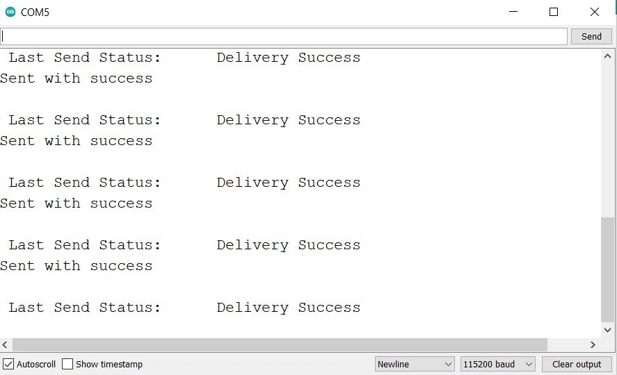
In the senders’ serial monitor you will be able to view the text that the message was successfully delivered.
Now, open the receiver side serial monitor. You will be able to see the messages being displayed on the receiver side after every 10 seconds for each sender board. These include the board ID with the MAC address, the message size in bytes and the random integer value which we specified in the program sketch.

Conclusion
In conclusion, we have learned about the ESP-NOW many-to-one communication configuration. As an example, we sent a small packet of data from multiple ESP32 boards to one ESP32 board without using any Wi-Fi or internet connection. You can use the same sketch to transfer useful data including sensor readings or even control the output pins of the ESP32 board through other ESP32 boards easily. Although, we have shown you ESP NOW one way communication( many to one configuration). But you can also use ESP NOW two-way communication as well to promptly transfer data two ways.
You may also like to read:
Great blog.
I noticed the struct_message structure for the three sender nodes are identical.
I have a situation where I want to receive two different struct_message structures (one is data that is three integers and a float and the other two floats). I suppose I could make both struct_messages the same by using dummy values but wondering if there is a better, more elegant way to receive multiple non equivalent structures.
What happens if two senders try and transmit at the same time ? Which message is received ??
I am looking for clarification on this topic as well. Multiple senders which may need to send multiple messages back to back. How to avoid losing data?