In this tutorial, we will create an ESP32 web server using ESP-NOW communication protocol and Wi-Fi simultaneously. The web server will display sensor readings received by a single ESP32 server board which will be sent by two other ESP32 boards via ESP-NOW one way communication protocol. Any appropriate sensor can be used such as DS18B20, BME680, LM35, and MPU6050 but for this project, we will use a DHT22 sensor which is used to measure temperature and humidity.
Recommended Components
The following components are used in this project or are helpful for building it with the ESP32.
| Component | How it’s used in this project | Buy on Amazon |
|---|---|---|
| ESP32 Development Board (DevKit V1) | The main microcontroller used throughout this project. | Check Price |
| Micro USB Cable | Powers the board and uploads the sketch from your computer. | Check Price |
| Breadboard | Provides a solderless base for wiring up the circuit. | Check Price |
| Jumper Wires | Connect the board to other components on the breadboard. | Check Price |
As an Amazon Associate we earn from qualifying purchases. Prices and availability are accurate as of the date/time indicated and are subject to change.
Prerequisites
We will use Arduino IDE to program our ESP32 development board. Thus, you should have the latest version of Arduino IDE. Additionally, you also need to install the ESP32 plugin.
If your IDE does not have the plugin installed you can visit the link below: Installing ESP32 library in Arduino IDE and upload code.
Required Components:
- 3x ESP32 development boards
- 2x DHT22 sensor
- 2x 4.7k ohm resistors (not required if using DHT22 module instead)
- Connecting Wires
- Breadboard
Project Overview ESP32 ESP-NOW and Wi-Fi Web Server
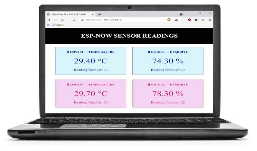
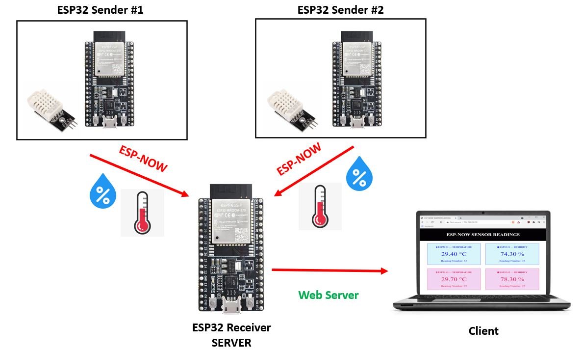
We will create an ESP32 web server that will display sensor readings obtained from two other ESP32 boards each connected with a DHT22 sensor. All the boards will be programmed using Arduino IDE. The web server will consist of a title, “ESP-NOW SENSOR READINGS,” and four boxes each for temperature and humidity readings from each of the ESP32 sender boards. Each box will contain a heading and its value underneath it. We aim to build a webpage that will display sensor readings obtained from BME280 connected with the ESP32 module.
The ESP32 server will receive temperature and humidity readings via ESP-NOW protocol (many to one configuration). Additionally, the transmission of these sensor readings from the server (ESP32 receiver) to the client (web page) will occur through Server-Sent Events. These readings will automatically update after every 10 seconds to new values when the web page receives them. Through SSE protocol, it will be very easy to update the sensor readings on our web page without adding any additional requests.
ESP-Now Web Server Working Process
- All three ESP32 boards including the receiver and sender boards will be configured to the same Wi-Fi channel. This channel will correspond to ESP32 receiver board’s Wi-Fi channel. The receiver ESP32 board will be set up as an access point as well as a station using WIFI_AP_STA.
- We will have a many-to-one ESP-NOW configuration where two ESP32 boards will send the sensor data to a single ESP32 receiver board.
- These sensor readings will be received by the ESP32 receiver board which will then act as a server and display the individual temperature and humidity readings on the web server. Both temperature and humidity readings from both the sensors will be displayed appropriately.
- Using Server Sent Events (SSE), the current readings will be updated simultaneously without the need to refresh the web page.
Installing Libraries for ESP32 ESP-NOW and Wi-Fi Web Server
Now let us install all the required libraries needed for the smooth functioning of this project. In total we will require five libraries. These include:
- ESPAsyncWebServer library
- Async TCP library
- Arduino_JSON library
- DHT library
- Adafruit Unified Sensor library
Installing ESPAsyncWebServer Library and Async TCP Library
The ESPAsyncWebServer library will help us in creating our web server easily. With this library, we will set up an asynchronous HTTP server. AsyncTCP library will also be incorporated as it a dependency for the ESPAsyncWebServer library. Both of these libraries are not available in the Arduino library manager. Therefore, we will have to download and load them on our ESP32 board ourselves.
Installing Arduino JSON Library
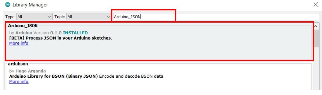
We also have to install the Arduino JSON library. Open your Arduino IDE and go to Sketch > Include Libraries > Manage Libraries. Type ‘Arduino_JSON’ in the search bar and install it.
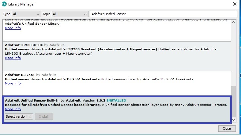
Installing DHT Library
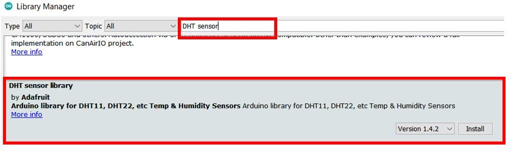
As we are connecting the DHT22 sensor with ESP32 sender boards so we will have to install DHT libraries to our module. We will require two libraries for this project:
- DHT sensor library
- Adafruit Unified Sensor library
We will use the Library Manager in our Arduino IDE to install the latest versions of the libraries. Open your Arduino IDE and go to Sketch > Include Libraries > Manage Libraries. Type each library name in the search bar and install them both.
Arduino Sketch for obtaining the MAC Address for the receiver ESP32 board
Open your Arduino IDE and go to File > New to open a new file. Copy the code given below in that file and save it.
#include <WiFi.h>

void setup(){
  Serial.begin(115200);
  Serial.println();

  Serial.println(WiFi.macAddress());
}

void loop(){

}
In the setup() function, we are opening the serial communication at a baud rate of 115200. Then by using the WiFi.macAddress() method we will obtain the unique MAC address of our ESP32 board in our serial monitor.
Make sure you choose the correct board and COM port before uploading your code to the board. Go to Tools > Board and select your board. Next, go to Tools > Port and select the appropriate port through which your board is connected. In this case, we are using the ESP32 Dev Module which is connected to COM5.
Click on the upload button to upload the code into the ESP32 development board. Press its ENABLE button after the sketch has been uploaded.

In your Arduino IDE, open up the serial monitor and you will be able to see the unique MAC address of your ESP32 module.
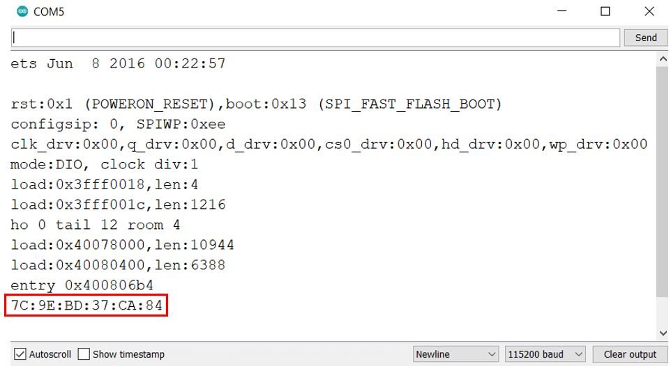
Obtain the MAC address for your receiver ESP32 board and label it. We will need the unique MAC address of the receiver board while programming the sender ESP32 boards.
ESP32 Web server and ESP-Now Receiver Arduino Sketch
Open your Arduino IDE and go to File > New to open a new file. Copy the code given below in that file and save it.
This sketch is for the single ESP32 receiver board that will receive sensor data from two other ESP32 sender boards. This sensor data will then be displayed on a web page where the receiver ESP32 board will act as the server.
#include <esp_now.h>
#include <WiFi.h>
#include "ESPAsyncWebServer.h"
#include <Arduino_JSON.h>
const char* ssid = "Your_SSID";
const char* password = "Your_Password";
// Structure example to receive data
// Must match the sender structure
typedef struct struct_message {
  int board_id;
  float temp;
  float hum;
  unsigned int Num_Readings;
} struct_message;
struct_message sensor_readings;
JSONVar board;
AsyncWebServer server(80);
AsyncEventSource events("/events");
void data_receive(const uint8_t * mac_addr, const uint8_t *incomingData, int len) {
  char macStr[18];
  Serial.print("Sensor Readings received from: ");
  snprintf(macStr, sizeof(macStr), "%02x:%02x:%02x:%02x:%02x:%02x",
           mac_addr[0], mac_addr[1], mac_addr[2], mac_addr[3], mac_addr[4], mac_addr[5]);
  Serial.println(macStr);
  memcpy(&sensor_readings, incomingData, sizeof(sensor_readings));

  board["board_id"] = sensor_readings.board_id;
  board["temperature"] = sensor_readings.temp;
  board["humidity"] = sensor_readings.hum;
  board["Num_Readings"] = String(sensor_readings.Num_Readings);
  String jsonString = JSON.stringify(board);
  events.send(jsonString.c_str(), "new_readings", millis());

  Serial.printf("Board ID %u: %u bytes\n", sensor_readings.board_id, len);
  Serial.printf("Temperature value: %4.2f \n", sensor_readings.temp);
  Serial.printf("Humidity value: %4.2f \n", sensor_readings.hum);
  Serial.printf("Number of Readings: %d \n", sensor_readings.Num_Readings);
  Serial.println();
}
const char index_html[] PROGMEM = R"rawliteral(
<!DOCTYPE HTML><html>
<head>
<title>ESP-NOW SENSOR READINGS</title>
<meta name="viewport" content="width=device-width, initial-scale=1">
<link rel="stylesheet" href="https://use.fontawesome.com/releases/v5.7.2/css/all.css" integrity="sha384-fnmOCqbTlWIlj8LyTjo7mOUStjsKC4pOpQbqyi7RrhN7udi9RwhKkMHpvLbHG9Sr" crossorigin="anonymous">
<link rel="icon" href="data:,">
<style>
html {font-family: New Times Roman; display: inline-block; text-align: center;}
p { font-size: 1.2rem;}
body { margin: 0;}
.topnav { overflow: hidden; background-color: #030103; color: white; font-size: 1.7rem; }
.content { padding: 20px; }
.card.esp1{ background-color: #d9f5fc; outline: 1px solid; }
.card.esp2{ background-color: #f2d3f2; outline: 1px solid; }
.cards { max-width: 700px; margin: 0 auto; display: grid; grid-gap: 2rem; grid-template-columns: repeat(auto-fit, minmax(300px, 1fr)); }
.reading { font-size: 2.8rem; }
.card.esp1 { color: #000cfc; }
.card.esp2 { color: #e81a57; }
</style>
</head>
<body>
<div class="topnav">
<h3>ESP-NOW SENSOR READINGS</h3>
</div>
<div class="content">
<div class="cards">
<div class="card esp1">
<h4><i class="fas fa-thermometer-half"></i> ESP32 #1 --- TEMPERATURE</h4><p><span class="reading"><span id="t1"></span> °C</span></p><p class="packet">Reading Number: <span id="rt1"></span></p>
</div>
<div class="card esp1">
<h4><i class="fas fa-tint"></i> ESP32 #1 --- HUMIDITY</h4><p><span class="reading"><span id="h1"></span> %</span></p><p class="packet">Reading Number: <span id="rh1"></span></p>
</div>
<div class="card esp2">
<h4><i class="fas fa-thermometer-half"></i> ESP32 #2 --- TEMPERATURE</h4><p><span class="reading"><span id="t2"></span> °C</span></p><p class="packet">Reading Number: <span id="rt2"></span></p>
</div>
<div class="card esp2">
<h4><i class="fas fa-tint"></i> ESP32 #2 --- HUMIDITY</h4><p><span class="reading"><span id="h2"></span> %</span></p><p class="packet">Reading Number: <span id="rh2"></span></p>
</div>
</div>
</div>
<script>
if (!!window.EventSource) {
var source = new EventSource('/events');
source.addEventListener('open', function(e) {
console.log("Events Connected");
}, false);
source.addEventListener('error', function(e) {
if (e.target.readyState != EventSource.OPEN) {
console.log("Events Disconnected");
}
}, false);
source.addEventListener('message', function(e) {
console.log("message", e.data);
}, false);
source.addEventListener('new_readings', function(e) {
console.log("new_readings", e.data);
var obj = JSON.parse(e.data);
document.getElementById("t"+obj.board_id).innerHTML = obj.temperature.toFixed(2);
document.getElementById("h"+obj.board_id).innerHTML = obj.humidity.toFixed(2);
document.getElementById("rt"+obj.board_id).innerHTML = obj.Num_Readings;
document.getElementById("rh"+obj.board_id).innerHTML = obj.Num_Readings;
}, false);
}
</script>
</body>
</html>)rawliteral";
void setup() {
Serial.begin(115200);
WiFi.mode(WIFI_AP_STA);
WiFi.begin(ssid, password);
while (WiFi.status() != WL_CONNECTED) {
delay(1000);
Serial.println("Setting as a Wi-Fi Station..");
}
Serial.print("Station IP Address: ");
Serial.println(WiFi.localIP());
Serial.print("Wi-Fi Channel: ");
Serial.println(WiFi.channel());
if (esp_now_init() != ESP_OK) {
Serial.println("Error initializing ESP-NOW");
return;
}
esp_now_register_recv_cb(data_receive);
server.on("/", HTTP_GET, [](AsyncWebServerRequest *request){
request->send_P(200, "text/html", index_html);
});
events.onConnect([](AsyncEventSourceClient *client){
if(client->lastId()){
Serial.printf("Client reconnected! Last message ID that it got is: %u\n", client->lastId());
}
client->send("Welcome!", NULL, millis(), 10000);
});
server.addHandler(&events);
server.begin();
}
void loop() {
static unsigned long last_time = millis();
static const unsigned long interval = 5000;
if ((millis() - last_time) > interval) {
events.send("ping",NULL,millis());
last_time = millis();
}
}How the Code Works?
Let us understand how the code works for the receiver ESP32 board.
Including Libraries
Firstly, we will include the relevant libraries which are necessary for this project. We are using four libraries for the receiver sketch: esp_now.h, WiFi.h, ESPAsyncWebServer.h and Arduino_JSON.h
esp_now.h for the ESP-NOW communication protocol, WiFi.h will allow our ESP32 board to use the Wi-Fi functionalities and ESPAsyncWebServer.h for the creation of asynchronous web server. Additionally, the Arduino_JSON library will be used as we will use a JSON variable to store the sensor readings from the sender boards. This variable with the readings will be later sent to web page.
#include <esp_now.h>
#include <WiFi.h>
#include "ESPAsyncWebServer.h"
#include <Arduino_JSON.h>
Setting Network Credentials
Next, we will create two global variables, one for the SSID and the other for the password. These will hold our network credentials which will be used to connect to our wireless network. Replace both of them with your credentials to ensure a successful connection.
const char* ssid = "Your_SSID";
const char* password = "Your_Password";Defining structure for receiving data
Now, we will define a structure named ‘struct_message’. This structure will be used to receive the data that will be received from the receiver ESP32 board via ESP NOW. The data includes an integer variable called ‘board_id’ to identify which sender board sent the message. As we are using two sender boards hence it can have a value of either 1 or 2. Next we have two floating variables called ‘temp’ and ‘hum.’ These hold the sensor readings for each respective field. The receiver board will also receive the readings number saved in the variable ‘Num_Readings.’ This number depicts the amount of readings sent to the receiver ESP32 board.
typedef struct struct_message {
int board_id;
float temp;
float hum;
unsigned int Num_Readings;
} struct_message;Next, we will create a new variable of type struct_message and call it ‘sensor_readings’. This will be used later on in the sketch to receive the data.
struct_message sensor_readings;Creating JSON variable
Moreover, we will also create a JSON variable called ‘board’ to store the individual sets of readings acquired from each sender board accordingly.
JSONVar board;Creating an AsyncWebServer Object
The AsyncWebServer object will be used to set up the ESP32 web server. We will pass the default HTTP port which is 80, as the input to the constructor. This will be the port where the server will listen to the requests.
AsyncWebServer server(80);Defining an EventSource
Next, we will define an event source called ‘/events.’ You can use any appropriate name.
AsyncEventSource events("/events");data_receive()
The data_receive() function acts as the callback function which we will define now. It will be used as a parameter when we will register this callback function for receiving messages. This prints the message on the serial monitor whenever a message is received from the ESP32 sender side. The message consists of the board ID, the size in bytes of the message, the current temperature, the current humidity and the number of readings along with the MAC address of the sender board.
void data_receive(const uint8_t * mac_addr, const uint8_t *incomingData, int len) {
char macStr[18];
Serial.print("Sensor Readings received from: ");
snprintf(macStr, sizeof(macStr), "%02x:%02x:%02x:%02x:%02x:%02x",
mac_addr[0], mac_addr[1], mac_addr[2], mac_addr[3], mac_addr[4], mac_addr[5]);
Serial.println(macStr);
memcpy(&sensor_readings, incomingData, sizeof(sensor_readings));
  board["board_id"] = sensor_readings.board_id;
  board["temperature"] = sensor_readings.temp;
  board["humidity"] = sensor_readings.hum;
  board["Num_Readings"] = String(sensor_readings.Num_Readings);
  String jsonString = JSON.stringify(board);
events.send(jsonString.c_str(), "new_readings", millis());
Serial.printf("Board ID %u: %u bytes\n", sensor_readings.board_id, len);
Serial.printf("Temperature value: %4.2f \n", sensor_readings.temp);
Serial.printf("Humidity value: %4.2f \n", sensor_readings.hum);
Serial.printf("Number of Readings: %d \n", sensor_readings.Num_Readings);
Serial.println();
}
Firstly, the sensor data being received from the sender side will be saved in the ‘sensor_readings’ structure variable that we created previously.
memcpy(&sensor_readings, incomingData, sizeof(sensor_readings));Secondly, we will create a JSON string variable called ‘jsonString’ which will contain the message being received.
board["board_id"] = sensor_readings.board_id;
board["temperature"] = sensor_readings.temp;
board["humidity"] = sensor_readings.hum;
board["Num_Readings"] = String(sensor_readings.Num_Readings);
String jsonString = JSON.stringify(board);
This json string will be sent to the web server by the receiver ESP32 board as an event called ‘new_readings’.
events.send(jsonString.c_str(), "new_readings", millis());Building the Web Page (HTML, CSS and JavaScript)
We will create an index_html variable to store all the HTML, CSS and JavaScript text which will be required to build our web page. It is more convenient to have separate HTML, CSS and JavaScript files saved on the ESP32 SPIFFS. All of these three files will later be linked together. For this article, we will not be using this approach but include everything inside our Arduino sketch instead.
We will start with the title of the web page. The tag will indicate the beginning of the title and the tag will indicate the ending. In between these tags, we will specify “ESP-NOW SENSOR READINGS” which will be displayed in the browser’s title bar.
<title>ESP-NOW SENSOR READINGS</title>Next, we will create a meta tag to make sure our web server is available for all browsers e.g., smartphones, laptops, computers etc.
<meta name="viewport" content="width=device-width, initial-scale=1">CSS styling
Inside the index_html variable we have the <style> </style> tags which mark the beginning and end of the CSS styling file.
We will set the display text to font type Times New Roman and align it in the centre of the webpage. For all the different texts and the boxes, the font size, font type, colour, positioning and everything relating to the overall visuals of the web page will be is specified. This section of code shows the CSS styling which we will incorporate in our web page.
<style>
    html {font-family: New Times Roman; display: inline-block; text-align: center;}
    p {  font-size: 1.2rem;}
    body {  margin: 0;}
    .topnav { overflow: hidden; background-color: #030103; color: white; font-size: 1.7rem; }
    .content { padding: 20px; }
    .card.esp1{ background-color: #d9f5fc; outline: 1px solid; }
      .card.esp2{ background-color: #f2d3f2; outline: 1px solid; }
    .cards { max-width: 700px; margin: 0 auto; display: grid; grid-gap: 2rem; grid-template-columns: repeat(auto-fit, minmax(300px, 1fr)); }
    .reading { font-size: 2.8rem; }
    .card.esp1 { color: #000cfc; }
 .card.esp2 { color: #e81a57; }
  </style>
HTML Body
The next step will be to define the HTML web page body. This will go inside the <body></body> tags which mark the beginning and the ending of the script. This part will include the heading of the web page and the boxes. We will include the heading of our webpage inside the <h3></h3> tags and it will be the same as that of the web browser title.
<h3>ESP-NOW SENSOR READINGS</h3>Displaying Sensor Readings
Next, we will include the following lines of code to display texts and boxes for temperature and humidity readings from each sender board.
<div class="content">
<div class="cards">
<div class="card esp1">
<h4><i class="fas fa-thermometer-half"></i> ESP32 #1 --- TEMPERATURE</h4><p><span class="reading"><span id="t1"></span> °C</span></p><p class="packet">Reading Number: <span id="rt1"></span></p>
</div>
<div class="card esp1">
<h4><i class="fas fa-tint"></i> ESP32 #1 --- HUMIDITY</h4><p><span class="reading"><span id="h1"></span> %</span></p><p class="packet">Reading Number: <span id="rh1"></span></p>
</div>
<div class="card esp2">
<h4><i class="fas fa-thermometer-half"></i> ESP32 #2 --- TEMPERATURE</h4><p><span class="reading"><span id="t2"></span> °C</span></p><p class="packet">Reading Number: <span id="rt2"></span></p>
</div>
<div class="card esp2">
<h4><i class="fas fa-tint"></i> ESP32 #2 --- HUMIDITY</h4><p><span class="reading"><span id="h2"></span> %</span></p><p class="packet">Reading Number: <span id="rh2"></span></p>
</div>
</div>
</div>The first two boxes will display the temperature and humidity readings received from ESP32 sender board #1 and the next two boxes will display the same sets of readings received from ESP32 sender board #2. We will specify the name, icon and colour for each box. We used the icons from Font Awesome Icons website. You can use any appropriate icon of your choice
Also, JavaScript will be in charge of handling the received data so that the readings will be updated correctly. This will be accomplished by using ids which we will reference in our script. Thus, whenever the client will receive a new event with the updated readings, the HTML elements with their respective ids will get updated to newer values.
JavaScript (Receiving and handling SSE events)
Inside the tags <script></script>, we will include the JavaScript to handle the SSE protocol. Its main aim will be to start the EventSource connection with the server and to handle the events which will be received from the server. We will mainly handle four kinds of occurrences:
- Connection
- Disconnection
- Messages sent by the server
- events
Firstly, we will define an event source and pass the /events URL inside it. This URL will send the updates to our web page.
if (!!window.EventSource) {
 var source = new EventSource('/events');
Then, we will use the addEventListener() function to listen to incoming events. It will have two arguments. The first will be the event name and the second will be function(e).
The following are listeners for connection, disconnection and incoming messages from the server. We used the default event listeners in this case which were listed in the Documentation.
 source.addEventListener('open', function(e) {
  console.log("Events Connected");
 }, false);
 source.addEventListener('error', function(e) {
  if (e.target.readyState != EventSource.OPEN) {
    console.log("Events Disconnected");
  }
 }, false);

 source.addEventListener('message', function(e) {
  console.log("message", e.data);
 }, false);
Next, we will include listeners for the event ‘new_readings.’ After every 5 seconds the ESP32 will receive new sensor readings from the sender boards. This event (new_readings) will be sent to the web server. When the client will receive the particular event, it will print the data on the browser console. Additionally, the new readings will also get saved to their elements with their respective ids.
 source.addEventListener('new_readings', function(e) {
  console.log("new_readings", e.data);
  var obj = JSON.parse(e.data);
  document.getElementById("t"+obj.board_id).innerHTML = obj.temperature.toFixed(2);
  document.getElementById("h"+obj.board_id).innerHTML = obj.humidity.toFixed(2);
  document.getElementById("rt"+obj.board_id).innerHTML = obj.Num_Readings;
  document.getElementById("rh"+obj.board_id).innerHTML = obj.Num_Readings;
 }, false);
setup()
Inside the setup() function, we will open a serial connection at a baud rate of 115200. Moreover, we will configure the receiver ESP32 board as an access point and as a station by using WiFi.mode(WIFI_AP_STA).
Serial.begin(115200);
WiFi.mode(WIFI_AP_STA);
The following section of code will connect our ESP32 board with the local network whose network credentials we already specified above. After the connection will be established, the IP address of the ESP32 board will get printed on the serial monitor. This will help us to make a request to the server.
  WiFi.begin(ssid, password);
  while (WiFi.status() != WL_CONNECTED) {
    delay(1000);
    Serial.println("Setting as a Wi-Fi Station..");
  }
  Serial.print("Station IP Address: ");
  Serial.println(WiFi.localIP());
Additionally, we will find out the receiver ESP32 board’s Wi-Fi channel as well. This will help us in the sender sketch to enable the senders to connect to the same Wi-Fi channel as the receiver board.
 Serial.print("Wi-Fi Channel: ");
 Serial.println(WiFi.channel());
The following lines of code will initialize the ESP-NOW protocol. In case of an unsuccessful connection, the serial monitor will display ‘Error initializing ESP-NOW.’
  if (esp_now_init() != ESP_OK) {
    Serial.println("Error initializing ESP-NOW");
    return;
  }
Now we will register the data_receive() function as the callback function as shown below. This will make sure that whenever a message will be received from the sender side, the data_receive() function will be called.
esp_now_register_recv_cb(data_receive);Handling Requests
We will configure the root / URL where our server will listen to HTTP GET requests.
The handling function will respond to the client by using the send_P() method on the request object. This method will take in three parameters. The first is 200 which is the HTTP status code for ‘ok’. The second is “text/html” which will correspond to the content type of the response. The third input is the text saved on the index_html variable which will be sent as the response.
 server.on("/", HTTP_GET, [](AsyncWebServerRequest *request){
    request->send_P(200, "text/html", index_html);
  });
The event source will be set up on our ESP32 board thorough the following lines of code:
  events.onConnect([](AsyncEventSourceClient *client){
    if(client->lastId()){
      Serial.printf("Client reconnected! Last message ID that it got is: %u\n", client->lastId());
    }

    client->send("Welcome!", NULL, millis(), 10000);
  });
  server.addHandler(&events);
To start the server, we will call the begin() on our server object.
server.begin();loop()
In the loop() function, after every 5 seconds we will ensure that the session is active.
void loop() {
  static unsigned long last_time = millis();
  static const unsigned long interval = 5000;
  if ((millis() - last_time) > interval) {
    events.send("ping",NULL,millis());
    last_time = millis();
  }
}
Demonstration
Choose the correct board and COM port before uploading your code to the board.
Go to Tools > Board and select ESP32 Dev Module.

Next, go to Tools > Port and select the appropriate port through which your board is connected.

Click on the upload button to upload the code into the ESP32 development board. After you have uploaded your code to the ESP32 development board press its ENABLE button.
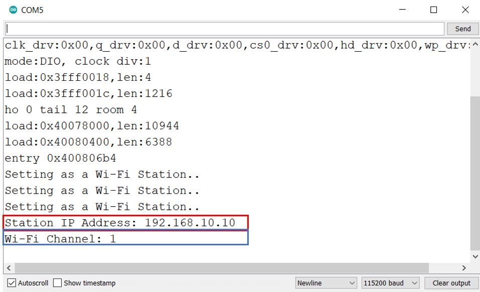
In your Arduino IDE, open up the serial monitor and you will be able to see the IP address of your ESP32 module as well as the Wi-Fi channel.
ESP32 ESP-Now Transmitter Schematic and Arduino Sketch
In this section, we will show you how to connect your ESP32 sender boards with DHT22 sensor and program them using Arduino IDE with the sender sketch.
DHT22 Pinout
The following figure shows the pinout diagram of DHT sensors. DHT sensor consists of four pins. But on DHT modules only three pins are exposed to the pinout of the module and the 10k ohm pull-up resistor is internally connected to pin 2.
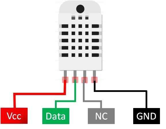
The following lists the pinout of the DHT sensor and their brief description. Pin number starts from left to right when you hold the sensor from the front end. It also shows how these pins will be connected with the ESP32 board.
| DHT22 Pin | ESP32 |
| 1 (VCC) | 3.3V |
| 2 (Data Out) | Any GPIO pins of ESP32 board along with 10k ohm pull-up resistor |
| 3 (NC) | Not used |
| 4 (GND) | Ground |
- VCC is the power supply pin. Apply voltage in a range of 3.3 V to 5.0 V to this pin
- Data Out is the digital output pin. It sends out the value of measured temperature and humidity in the form of serial data
- N/C is not connected
- GND: Connect the GND pin
DHT22 Interfacing with ESP32 sender board
Connect the DHT22 to ESP32 along with a 10K ohm pull-up resistor. The connection diagram is shown in the picture below.
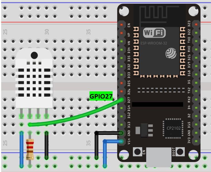
- The first pin is the power supply (VCC) pin. Connect it with the 3.3 volt pin of ESP32.
- Data out is the pin through which we get temperature and humidity samples from the DHT sensor. Connect this pin with GPIO27 of ESP32 and also connect the data pin with a 10k pull-up resistor. You can also use any appropriate digital pin of ESP32.
A Pull-up resistor is used to keep the data pin high for proper communication between the microcontroller and sensor. You can check the datasheet of DHT11 and DHT22 to get more information about it. DHT22 is also known by the name of AM2302.
- Third pin is not used
- Connect the fourth pin (GND) to the ground pin of the ESP32 board
Arduino Sketch ESP32 Sender
Open your Arduino IDE and go to File > New to open a new file. Copy the code given below in that file and save it.
This sketch sends a structure containing the data to the receiver ESP32 board using ESP-NOW communication protocol (many-to-one configuration). Make sure to replace the SSID.
#include <esp_now.h>
#include <esp_wifi.h>
#include <WiFi.h>
#include <Adafruit_Sensor.h>
#include <DHT.h>

#define board_ID 1

#define DHTPIN 27
#define DHTTYPE    DHT22
DHT dht(DHTPIN, DHTTYPE);

//MAC Address of the receiver
uint8_t broadcastAddress[] = {0x7C, 0x9E, 0xBD, 0x37, 0x28, 0x4C};


typedef struct struct_message {
    int board_id;
    float temp;
    float hum;
    int Num_Readings;
} struct_message;

struct_message sensor_readings;

unsigned long previous_time = 0;
const long interval = 10000;

unsigned int Num_Readings = 0;

constexpr char wifi_SSID[] = "PTCL-BB";

int32_t obtain_wifi(const char *ssid) {
  if (int32_t n = WiFi.scanNetworks()) {
      for (uint8_t i=0; i<n; i++) {
          if (!strcmp(ssid, WiFi.SSID(i).c_str())) {
              return WiFi.channel(i);
          }
      }
  }
  return 0;
}

float get_temperature() {
  float t = dht.readTemperature();
  if (isnan(t)) {
    Serial.println("Failed to read from DHT sensor!");
    return 0;
  }
  else {
    Serial.println(t);
    return t;
  }
}

float get_humidity() {
  float h = dht.readHumidity();
  if (isnan(h)) {
    Serial.println("Failed to read from DHT sensor!");
    return 0;
  }
  else {
    Serial.println(h);
    return h;
  }
}

void data_sent(const uint8_t *mac_addr, esp_now_send_status_t status) {
  Serial.print("\r\nLast Readings Send Status:\t");
  Serial.println(status == ESP_NOW_SEND_SUCCESS ? "Delivery Success" : "Delivery Fail");
}

void setup() {
  Serial.begin(115200);
  dht.begin();

  WiFi.mode(WIFI_STA);
  int32_t channel = obtain_wifi(wifi_SSID);
  WiFi.printDiag(Serial);
  esp_wifi_set_promiscuous(true);
  esp_wifi_set_channel(channel, WIFI_SECOND_CHAN_NONE);
  esp_wifi_set_promiscuous(false);
  WiFi.printDiag(Serial);

  if (esp_now_init() != ESP_OK) {
    Serial.println("Error initializing ESP-NOW");
    return;
  }


  esp_now_register_send_cb(data_sent);

  esp_now_peer_info_t peerInfo;
  memcpy(peerInfo.peer_addr, broadcastAddress, 6);
  peerInfo.encrypt = false;
  if (esp_now_add_peer(&peerInfo) != ESP_OK){
    Serial.println("Failed to add peer");
    return;
  }
}

void loop() {
  unsigned long current_time = millis();
  if (current_time - previous_time >= interval) {
    previous_time = current_time;
    sensor_readings.board_id = board_ID;
    sensor_readings.temp = get_temperature();
    sensor_readings.hum = get_humidity();
    sensor_readings.Num_Readings = Num_Readings++;

    esp_err_t result = esp_now_send(broadcastAddress, (uint8_t *) &sensor_readings, sizeof(sensor_readings));
    if (result == ESP_OK) {
      Serial.println("Sent with success");
    }
    else {
      Serial.println("Error sending the data");
    }
  }
}
How the Code Works?
Including Libraries
Firstly, we will include the necessary libraries. For the sender sketch, we are using five of them. The esp_now.h for the ESP-NOW communication protocol and WiFi.h will allow our ESP32 board to use the Wi-Fi functionalities. The DHT and Adafruit sensor libraries are the ones that we previously installed and will be required for the functionality of the DHT sensor.
#include <esp_now.h>
#include <esp_wifi.h>
#include <WiFi.h>
#include <Adafruit_Sensor.h>
#include <DHT.h>
Defining Board ID
Secondly, we will define the board ID of the sender ESP32 board. As this sketch is for ESP32 sender board #1 hence the board_ID is set to 1.
Make sure to change the ID (1 or 2) accordingly when you upload this sketch to both the sender boards. For ESP32 sender board #1, the board_ID is ‘1’ and for ESP32 sender board #2, the board_ID will be ‘2’
#define board_ID 1Defining DHT Sensor
The following lines of code will specify the type of DHT sensor and the GPIO pin of the sender ESP32 board which we will connect with the data pin of the sensor. We are using GPIO27 that will be connected with the data pin of the DHT sensor. You can use any appropriate GPIO pin.
#define DHTPIN 27
#define DHTTYPE    DHT22
DHT dht(DHTPIN, DHTTYPE);
Specifying Receiver MAC Address
Secondly, we will specify the MAC Address of the ESP32 board which will act as the receiver. We will use the same ESP32 board which we used in the sketch above when finding the MAC address. Replace the address with the unique MAC address of your own ESP32 board. You can use the sketch which was given previously, to find the MAC address of your module.
uint8_t broadcastAddress[] = {0x7C, 0x9E, 0xBD, 0x37, 0x28, 0x4C};Defining structure for sending data
Now, we will define the same structure named ‘struct_message’ which we did for the receiver sketch. Inside the structure, we will initialize the variables which will hold our data that we will transmit to the receiver board via ESP-NOW. Make sure that the structure is the same in both the sketches.
typedef struct struct_message {
    int board_id;
    float temp;
    float hum;
    int Num_Readings;
} struct_message;
Next, we will create a new variable of type struct_message and call it sensor_readings. This will be used later on in the sketch to acquire the data and transmit it accordingly
struct_message sensor_readings;Adding delay
The sender ESP32 will send sensor readings after every 30 seconds. We will incorporate this value in the ‘interval’ variable in milliseconds.
unsigned long previous_time = 0;
const long interval = 10000;
Defining Reading Number
Next, we will define the reading number as an integer variable and set it to 0. This will increment after each set of reading (temperature + humidity) has been sent over to the receiver side.
unsigned int Num_Readings = 0;Assigning Wi-Fi channel
The following lines of code will allot the same Wi-Fi channel of the receiver ESP32 to the sender ESP32 board. Make sure you enter the same SSID as you did for the receiver sketch. This will allot the same Wi-Fi channel for both the receiver-sender boards.
constexpr char wifi_SSID[] = "Your_SSID";

int32_t obtain_wifi(const char *ssid) {
  if (int32_t n = WiFi.scanNetworks()) {
      for (uint8_t i=0; i<n; i++) {
          if (!strcmp(ssid, WiFi.SSID(i).c_str())) {
              return WiFi.channel(i);
          }
      }
  }
  return 0;
}
get_temperature()
The get_temperature() function returns the current temperature reading if the DHT sensor is working properly. Through dht.readTemperature(), the temperature reading will get saved in the variable ‘t.’ Moreover, if the connection between the module and the sensor is incorrect or the values are not being accessed properly then an error message will be printed. This will help us in debugging our circuit or a possible issue in the initialization of the sensor. If the sensor is working properly then the temperature reading gets printed on the serial monitor.
float get_temperature() {
  float t = dht.readTemperature();
  if (isnan(t)) {
    Serial.println("Failed to read from DHT sensor!");
    return 0;
  }
  else {
    Serial.println(t);
    return t;
  }
}
get_humidity()
The get_humidity() function returns the current humidity reading if the DHT sensor is working properly. Through dht.readHumidity(), the humidity reading will get saved in the variable ‘h.’ Moreover, if the connection between the module and the sensor is incorrect or the values are not being accessed properly then an error message will be printed. This will help us in debugging our circuit or a possible issue in the initialization of the sensor. If the sensor is working properly then the humidity reading gets printed on the serial monitor.
float get_humidity() {
  float h = dht.readHumidity();
  if (isnan(h)) {
    Serial.println("Failed to read from DHT sensor!");
    return 0;
  }
  else {
    Serial.println(h);
    return h;
  }
}
data_sent()
The data_sent() function acts as the callback function which we will define now. It will be used as a parameter when we will register this callback function for sending messages. This prints whether the message was successfully delivered or not on the serial monitor whenever a message will be sent from the ESP32 sender side.
void data_sent(const uint8_t *mac_addr, esp_now_send_status_t status) {
  Serial.print("\r\nLast Readings Send Status:\t");
  Serial.println(status == ESP_NOW_SEND_SUCCESS ? "Delivery Success" : "Delivery Fail");
}
setup()
Inside the setup() function, we will start the serial communication at a baud rate of 115200. Moreover, we will initiate the connection with the DHT sensor using dht.begin().
 Serial.begin(115200);
  dht.begin();
We will set up the sender ESP32 as a Wi-Fi station.
WiFi.mode(WIFI_STA);The following lines will make sure that the sender ESP board’s Wi-Fi channel is the same as that of the receiver ESP32 board.
  int32_t channel = obtain_wifi(wifi_SSID);
  WiFi.printDiag(Serial);
  esp_wifi_set_promiscuous(true);
  esp_wifi_set_channel(channel, WIFI_SECOND_CHAN_NONE);
  esp_wifi_set_promiscuous(false);
  WiFi.printDiag(Serial);
The following lines of code will initialize the ESP-NOW protocol. In case of an unsuccessful connection, the serial monitor will display ‘Error initializing ESP-NOW.’
 if (esp_now_init() != ESP_OK) {
    Serial.println("Error initializing ESP-NOW");
    return;
  }
Now we will register the data_sent() function as the callback function. This will make sure that whenever a message will be sent from the sender side, the data_sent() function will be called.
esp_now_register_send_cb(data_sent);The following lines of code will pair the sender and receiver ESP32 boards.
  esp_now_peer_info_t peerInfo;
  memcpy(peerInfo.peer_addr, broadcastAddress, 6);
  peerInfo.encrypt = false;
  if (esp_now_add_peer(&peerInfo) != ESP_OK){
    Serial.println("Failed to add peer");
    return;
  }
loop()
Inside the loop() function, the sender board will transmit the data to the receiver ESP32 board. After every 10 seconds, the current temperature and humidity reading along with the board ID and the number of readings will be sent to the receiver side.
  unsigned long current_time = millis();
  if (current_time - previous_time >= interval) {
    previous_time = current_time;
    sensor_readings.board_id = board_ID;
    sensor_readings.temp = get_temperature();
    sensor_readings.hum = get_humidity();
    sensor_readings.Num_Readings = Num_Readings++;
Then the sender board will send the message and monitor if it was sent successfully or not.
    esp_err_t result = esp_now_send(broadcastAddress, (uint8_t *) &sensor_readings, sizeof(sensor_readings));
    if (result == ESP_OK) {
      Serial.println("Sent with success");
    }
    else {
      Serial.println("Error sending the data");
    }
Demonstration
Choose the correct board and COM port before uploading your code to the sender board.
Go to Tools > Board and select ESP32 Dev Module.
Next, go to Tools > Port and select the appropriate port through which your board is connected.
Click on the upload button to upload the code into the ESP32 development board. After you have uploaded your code to the ESP32 development board press its ENABLE button.
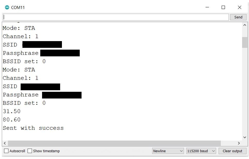
In your Arduino IDE, open up the serial monitor and you will be able to see that the sender ESP32 board has the same Wi-Fi channel as that of the receiver board. In our case it is channel 1.
Next, follow the same steps and upload the sender side sketch to the other sender ESP32 module as well. Make sure to change the board ID to ‘2’ in this case. Now you will have two sender ESP32 boards programmed with the sender sketch but having different board IDs (1 or 2).
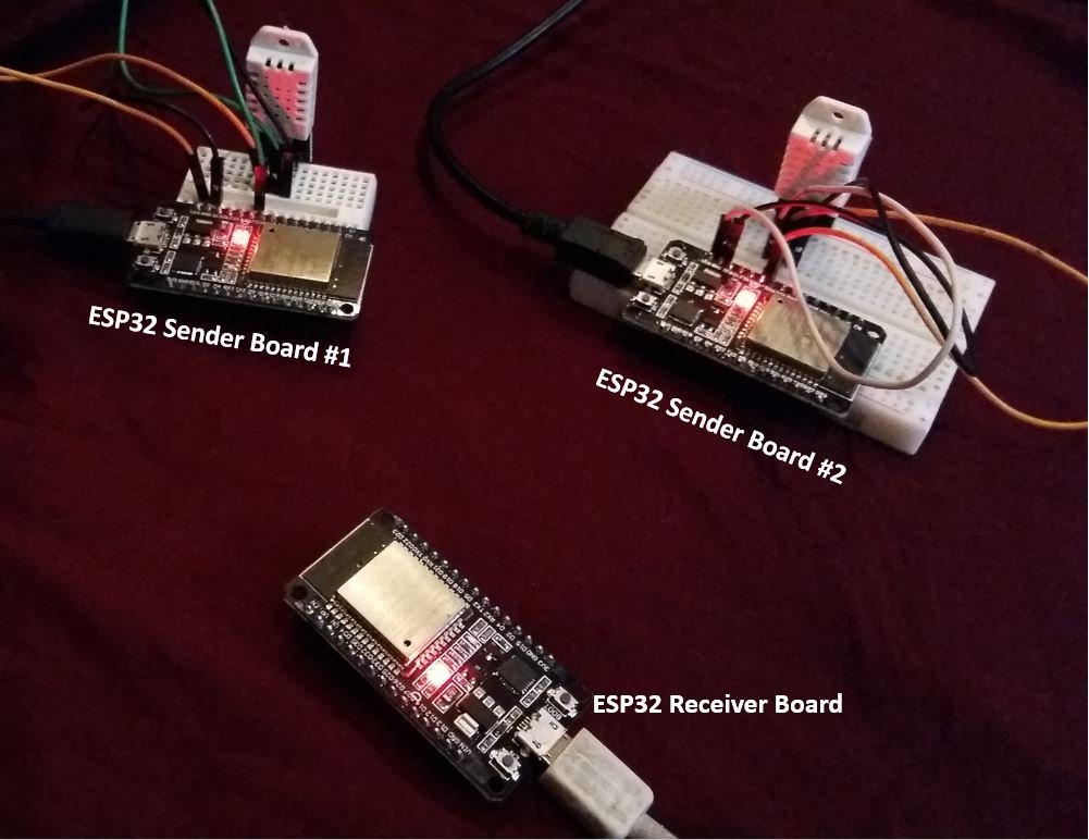
Demonstration ESP32 ESP-NOW + Wi-Fi based Web Server
Now after uploading both of the sender and receiver sketches onto their respective ESP32 boards let us move towards the final demonstration of the project. Make sure all the three boards are powered on throughout the demonstration.
Now open the receiver board’s serial monitor and copy the IP address given there on a web browser and press enter.
This will open the ESP-NOW web server that we created.
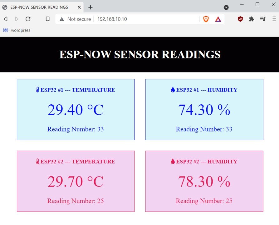
Notice that we have separate coloured blocks for sender ESP32 #1 and sender ESP32 #2 where they display the current temperature reading, current humidity reading and the number of readings. These values automatically get updated through server sent events protocol without the need to refresh the we page.
Conclusion
In conclusion, we were able to build an ESP32 ESP-NOW + Wi-Fi based web server following the many-to-one ESP-NOW configuration. We used DHT22 sensor connected with two ESP32 sender boards to transfer the current temperature and humidity readings to the receiver ESP32 board. The ESP32 receiver board then hosted a web server to display these readings where they were automatically updated using SSE.
For more articles related to ESP-NOW, Server Sent Events (SSE), and DHT22 sensor follow the links below.
ESP-NOW:
- ESP32 ESP-NOW Getting Started Tutorial with Arduino IDE
- ESP32 ESP-NOW Two way Communication (Arduino IDE)
- ESP-NOW ESP32 Send Data to Multiple boards (One to Many Communication)
- ESP32 ESP-NOW Receive Data from Multiple boards (Many to One Communication)
- ESP32 ESP-NOW Send and Receive Encrypted Messages
Server-Sent-Events (SSE):
- ESP32 Server-Sent Events (SSE) Web Server (Arduino IDE)
- ESP8266 NodeMCU Server-Sent Events (SSE) Web Server (Arduino IDE)
DHT11/22 Sensor:
Great content !!!!
hello.
very good tutorial for me.
but, I have a problem, all data in the html viewer are with 3 decimal, (3.000), and I don’t need this !
how can I fix this ?
thx.
patrick.
how to upload sensor data received through espnow from slave esp to master esp to thingspeak cloud using wifi by master esp
thanks in advance..!
You can modify this project to send data to Thingspeak by following this guide:
https://microcontrollerslab.com/esp32-send-sensor-readings-thingspeak-arduino-ide/
I want to Send a POST request of sensor data received from another esp32 via esp_now to a API , can you tell the modifications to be done in the above code.