Temperature measurement is a crucial aspect in numerous applications, spanning from weather monitoring to industrial processes. The ability to accurately and efficiently measure temperature plays a vital role in ensuring the optimal performance and safety of various systems. In this article, we will explore the implementation of a digital temperature measurement system using a microcontroller. By utilizing components such as the PIC16F887A microcontroller, LM35 temperature sensor, and an LCD display, we will look into the circuitry, code, and practical aspects of this project.
Components
To build this system, we require the following components:
1. PIC16F877A Microcontroller
The PIC16F877A microcontroller is a powerful and easy-to-program 8-bit microcontroller. It features 256 bytes of EEPROM data memory and self-programming capabilities. The operating voltage range is between 2V and 5.5V, making it versatile for various projects. It also includes 2 comparators, a 10-bit Analog-to-Digital Converter (ADC), and PWM functions, making it suitable for interfacing with LCDs and sensors.
2. Pickit 3 Programmer
To program the PIC16F877A microcontroller, we require a Pickit 3 programmer. This programmer is compatible with the MPLAB Integrated Programmer Environment (IPE) and allows for easy programming of the microcontroller.
3. LCD 16×2 Display
A 16×2 LCD display is used to show the temperature readings. It consists of 16 pins and requires a 10K ohm potentiometer to adjust the contrast. The display also includes a backlight LED. The LCD is capable of displaying 16 characters in two lines, providing sufficient space for temperature display.
4. LM35 Temperature Sensor
The LM35 is an inexpensive yet precise temperature sensor. It has a temperature measurement range between -50°C to 150°C and operates from 4V to 30V, consuming less than 60μA current. Compared to other temperature sensors, the LM35 is more efficient, as it is made up of an integrated circuit with no risk of damaging internal circuitry. Additionally, it draws current only in micro Amperes, making it ideal for portable projects.
Others
Other components required for this project include a breadboard, jumper wires, and a 10K ohm potentiometer.
LM35 Temperature Sensor Interfacing with Pic Microcontroller
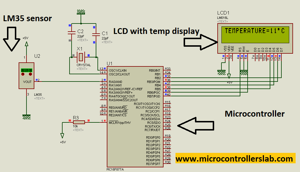
The LM35 temperature sensor converts temperature into an analog voltage value. Pin one and three of the LM35 are connected to the 5-volt power supply, whereas pin two outputs the analog voltage proportional to the temperature value. The relationship between the measured temperature and the analog output voltage is 1°C = 10mV.
To measure the analog voltage value, we use the PIC16F887A microcontroller’s built-in ADC. The microcontroller has seven built-in ADC channels, allowing for easy interfacing with multiple sensors. After reading the ADC value, the voltage is converted back into temperature using a conversion factor. The temperature value is then displayed on the LCD, which is connected to PORTB of the microcontroller.
Circuit Diagram
The circuit diagram for the digital temperature sensor is shown below:
The circuit diagram illustrates how the components, including the PIC16F877A microcontroller, LM35 temperature sensor, and LCD display, are interconnected to form a complete temperature measurement system. By using the microcontroller’s analog-to-digital converter (ADC) to read the voltage from the LM35 temperature sensor and utilizing specific code, the temperature value can be converted and displayed on the LCD screen.
To protect the LM35 and microcontroller, it is recommended to connect an 80K ohm resistor in parallel to the output of the temperature sensor.
NOTE: Before starting this project, it is recommended to learn about LCD interfacing with a Pic microcontroller, especially the hardware part. Understanding this will help avoid any issues during the project implementation.
Code
The code for this project is written in the MIKROC compiler. It includes sections for reading the temperature, converting the data, and displaying it on the LCD. If you do not know how to use MikroC for Pic, you can refer to these tutorials:
- How to Use “MikroC PRO for PIC” to Program PIC Microcontrollers
- Pic microcontroller programming in c using Mikroc Pro for PIC
In programming part conversion factor is used to convert voltage back into temperature.The conversion factor is:
- 1 volt = 100 degree
- temp = ( Output voltage * 100 oC/V )
- Code is written in MIKRO C compiler.
// LCD module connections
sbit LCD_D7 at RB2_bit;
sbit LCD_D6 at RB3_bit;
sbit LCD_D5 at RB4_bit;
sbit LCD_D4 at RB5_bit;
sbit LCD_EN at RB6_bit;
sbit LCD_RS at RB7_bit;

sbit LCD_D7_Direction at TRISB2_bit;
sbit LCD_D6_Direction at TRISB3_bit;
sbit LCD_D5_Direction at TRISB4_bit;
sbit LCD_D4_Direction at TRISB5_bit;
sbit LCD_EN_Direction at TRISB6_bit;
sbit LCD_RS_Direction at TRISB7_bit;

int temp;
char temper[7];

void READ_temp(void)
{
    temp = ADC_Read(0);
    temp = temp * 5/1023;
    temp = temp * 100;
}

void data_conversion(void)
{
    inttostr(temp, temper);
}

void display_temperature(void)
{
    lcd_out(1, 1, "TEMPERATURE=");
    lcd_out(1, 13, Ltrim(temper));
    Lcd_Chr_Cp(0xdf);
    Lcd_Chr_Cp('C');
    Lcd_Chr_Cp(' ');
}

void main()
{
    ADC_Init();
    Lcd_Init(); // Initialize LCD
    Lcd_Cmd(_LCD_CLEAR); // Clear display
    lcd_cmd(_LCD_CURSOR_OFF);
    lcd_out(1, 4, "DIGITAL TEMPERATURE");
    lcd_out(2, 6, "SENSOR");
    delay_ms(1000);
    Lcd_Cmd(_LCD_CLEAR); // Clear display

    while(1)
    {
        READ_temp();
        data_conversion();
        display_temperature();
    }
}
How Does Code Work?
Here’s an explanation of each line of code:
// LCD module connections
sbit LCD_D7 at RB2_bit;
sbit LCD_D6 at RB3_bit;
sbit LCD_D5 at RB4_bit;
sbit LCD_D4 at RB5_bit;
sbit LCD_EN at RB6_bit;
sbit LCD_RS at RB7_bit;

sbit LCD_D7_Direction at TRISB2_bit;
sbit LCD_D6_Direction at TRISB3_bit;
sbit LCD_D5_Direction at TRISB4_bit;
sbit LCD_D4_Direction at TRISB5_bit;
sbit LCD_EN_Direction at TRISB6_bit;
sbit LCD_RS_Direction at TRISB7_bit;
These lines define the connections between the PIC microcontroller and the LCD module. The sbit keyword is used to define individual bits of the microcontroller’s ports (RB2, RB3, RB4, RB5, RB6, RB7) as corresponding pins of the LCD module. The sbit LCD_D7_Direction at TRISB2_bit; lines set the direction of the LCD pins as output.
int temp;
char temper[7];
Here, two variables are declared: temp to store the temperature value and temper, an array of characters to store the converted temperature value.
void READ_temp(void)
{
    temp = ADC_Read(0);
    temp = temp * 5/1023;
    temp = temp * 100;
}
This function reads the temperature value from the ADC (Analog-to-Digital Converter) channel 0. The ADC_Read(0) function returns a value in the range of 0 to 1023, which represents the analog voltage value. The temp value is then converted to temperature by multiplying it with a conversion factor.
void data_conversion(void)
{
    inttostr(temp, temper);
}
This function converts the integer temperature value (temp) into a string format (temper) using the inttostr() function. It enables the temperature value to be displayed on the LCD.
void display_temperature(void)
{
    lcd_out(1, 1, "TEMPERATURE=");
    lcd_out(1, 13, Ltrim(temper));
    Lcd_Chr_Cp(0xdf);
    Lcd_Chr_Cp('C');
    Lcd_Chr_Cp(' ');
}
This function displays the temperature value on the LCD. The lcd_out() function is used to output the string “TEMPERATURE=” at the specified position on the LCD (line 1, column 1). The Ltrim() function is used to remove any leading spaces from the temper string. The Lcd_Chr_Cp() function is used to display the degree symbol (0xdf) followed by the letter ‘C’ on the LCD.
void main()
{
    ADC_Init();
    Lcd_Init(); // Initialize LCD
    Lcd_Cmd(_LCD_CLEAR); // Clear display
    lcd_cmd(_LCD_CURSOR_OFF);
    lcd_out(1, 4, "DIGITAL TEMPERATURE");
    lcd_out(2, 6, "SENSOR");
    delay_ms(1000);
    Lcd_Cmd(_LCD_CLEAR); // Clear display

    while(1)
    {
        READ_temp();
        data_conversion();
        display_temperature();
    }
}
The main() function is the entry point of the program. It initializes the ADC and LCD by calling the ADC_Init() and Lcd_Init() functions, respectively. The Lcd_Cmd(_LCD_CLEAR) function is used to clear the LCD display. The lcd_cmd(_LCD_CURSOR_OFF) turns off the cursor on the LCD. The lcd_out() functions are used to output the specified strings on the LCD. After a brief delay, the while loop starts, continuously reading the temperature, converting it, and displaying it on the LCD.
Demonstration
To fully simulate and obtain the hex file for this project, please refer to the following link: Temperature Sensor using PIC Microcontroller.
Conclusion
Implementing a digital temperature measurement system using a microcontroller provides a cost-effective and accurate solution. By utilizing the LM35 temperature sensor and the PIC16F887A microcontroller, it is possible to measure and display temperature readings with ease.
You may also like to read:
Great work Bilal please send complete simulation and the hex file most preferably including proteus sketches too
post your email address in comment to get complete project of digital temperature sensor.
if you kindly send me the full project manual it will very helpful for me. I have a little time for submit this project in our final exam.
please help me the project in full especially the code segment
chriecy@outlook.com
sir please send me code
Please send me the hex file and the code. sanderjacob13@gmail.com
sir can you help me with me thesis about battery management system.
that can monitor voltage, current, state of charge of individual battery
I want a full code of this. please send me at syedbaqirraza47@gmail.com .
Hey! Do you have the assembly language code of this project? Kindly send the hex file. I’ll be grateful to you
Dear Mr. Bilal,
Good day,
Please Send me Hex file and Circuit diagram of this Project on my email.
Download link is available at the end of this post
can you give your full source code for this project ?
i like the project i need to work please send me the full proteus and hex file
here is my email
cherusman49@gmail.com
can i have a copy of the hex file and also DNS.thank you
microPLEC@gmail.com
hello ,can i have your full source code and hex file .help me please 🙂 . my email – ameyyame@gmail.com .
I have updated this post with downloading link of temperature sensor.you can download now
excuse me , why i cant compile your coding in mikroC compiler .Its error 🙁 . Help me pls . I need to edit your coding .thanks
Use link given at the end of this article to download code and simulation and there is no error in this code I have complied it before upload on this post
please send me too .”
syedbaqirraza47@gmail.com
Sir Smoge and temprature detector using assembly instructions. k liye components and coding btaaa dein. please.
Hi i need correct program and hex code for this project can you please send me
Hi,Can you send me simulation and the hex file of this project.
hi malik,
thank you for this good job, i don’t understand the function Ltrim and how to display a negative temperature
thanks a lot
is the correct code? proteus simulation is availablre?
yar plz send me the full code, hex file and circuit diagram
nice work
could please send me the hexa file
I am doing my project on load cell, in that i want to display load cell ouput voltage into load value,for that i am using PIC16f877a..Anyone pls help me
very nice project please send me the related project & its format
Very nice project…
Pls send me the complete project and hex file.
How do i open .dns file.
Thanks
Code and circuit diagram of temperature sensor project is available in article
Thanks man, i have seen it and it is working perfectly.
Can you please assist me on how to connect numeric keypad and alarm system(buzzer) so it beeps at a particular temperature.
Thank you.
Pls my email address is bentumsamuel@gmail.com
i want complete coding of this project please send me
Please it is a build up on your already existing project. I am having challenges interfacing it with a buzzer to beep and lcd at to light red at a temperature of about 80 degree celcius.
I really appreciate your assistance. Thank you.
The link to the codes is : http://www.4shared.com/get/9qt8y495ba/temperature_sensor.html.
You can download with email: bentumsamuel@gmail.com and password: sammie.
Thanks.
plz give me code and hex file of temprature sensor using pic16f877a
Check the link given at the end of post for code and hexa file
Pls how do you include a buzzer to the project so it sounds at a particular temperature. Thanks.
Nice worl. Implementing it but having challenges displaying on lcd screen. Pls help.
Nice work. Implementing it but having challenges displaying on lcd screen. Pls help.
Nice project, Have downloaded zip file.Please which compiler did you use. Everything complete except header files missing in codes. Can you please send me the complete work with header file. Email: bentumsamuel@gmail.com
Thanks
I have used Mikro c pro complier
its a good thing to find your blog today!!
I want to do two projects;
first; i wants to measure and display room temperature and humidity at real-time , or every 2seconds, I need one pin to be high and low at 1hr intervals,
Also i want one pin to be high for only 5 seconds after every 2hrs,
these are for alarms, one pin high per each condition ,when temperature is at 34c, 36c, 38c 39c and 39.5c
in case of humidity, one pin high per each condition , when humidity is at 50%, 60% and 70%
I want it to control my homemade incubator , I hope you can add to a certain pins which will control the heaters for generating temperature and humidity default temp. is 37.8c and humidity is 65%, so any deviation from these defaults the pins assigned will act accordingly from there it will stabilizer the condition
is it possible to add several buttons for setting the completed unit? if possible it will be awesome to include. Please kindly suggest the circuit diagram and the codes.
Let me end here with only the first .
Sorry for my bad English, I am from Africa, Tanzania. I am waiting for you to inbox me via nziku99@gmail.com , thanks in advance
nice work cued u like to send
me full code and hex file?
pls send me project with all files
Hey there,
I wish to add a keypad to this same project, such that, message on the lcd ask me press (*),
Then ” Enter Code”. If the right code is entered, then the temperature is displayed.
if Wrong code is entered, Code error message is displayed.
Can you please help with a complete source code?
I am using the MikroC IDE
Hello, Bilal. I’ve tried to download the .zip file from the link you’ve given here, but it tells me the link is invalid. So may i ask you to send it to my email address? its rqzanturchin94@gmail.com
Thank you, Sir!
THANK YOU SIR. IT HELPED ME A LOT.
PLEASE SHARE A CODE FOR I.R BASED R.P.M MEASUREMENT WITH PPIC16F877A.
hello ,can i have your full source code and hex file .help me please 🙂 . my email – guan.momo@gmail.com
code is given in article
code is given in article
Dear Sir,
I am Shrikant M and Pursuing B.E final year. I came across your site
and it’s really to say that your web site is amazing which provides
new trends techno project ideas. So, I am doing project on the title
“Temperature control in PROTEUS using ADC with motor attached to it”.
Its like when temperature is high then RPM of motor should be more and
vise versa. In addition to that I needed to add any feature by adding
TRANSISTOR. But I am not getting sir. Please help me out this. I saw
your all projects So, your one of the expert.
Please send me the design of such project and its C-code. I am using
8051 or 8951. Please send me ADC-Motor-LCD-TRANSISTOR-Any other
feature. Please send sir and your help will be like star for me.
Thanking You,
Shrikant M
shrshr03@rediffmail.com
Great project .would like to build one myself. Hope to get hold of a complete code .
Dear Sir,
My logic is that
— –> From 0-19 Celsius, Fan OFF and Heater ON
— –> 20-25 Normal Temp. Fan OFF and Heater OFF
— –>26-30 Fan ON at 1 level
— –> More than 30, Fan level 2.
With above logic I wanted to add one more feature. I am not getting sir. So, I am seeking help from you because you the one who can help me out. Project dates are very near sir. I wanted in Embedded C program. I am using Keil software. Please check my previous circuit. Kindly, help me out.
Thanking You,
Shrikant M
shrshr03@rediffmail.com
i have a couple of questions:
what is the range of temperature which can be sensed?
is this similar to the thermometer?
Please send me the whole project with software
thanks
ahnuman2001@gmail.com
Ali Hussein
I need to know how to show negative temperatures. Please send me the code.
it is a good project .i need temperature sensor project with buzzer which beep at above 40 c using pic18f452 in assembly languange .
plzzz sir sent me all detail about the project.
nk04156@gmail.com
Hi! I downloaded all the files and simulated it. But there is no display in the lcd, just the white background indicating that it is running. But no texts display. Pls help
microcontrollerslabhub@gmail.com plz send me the codes of temparature sensors
can i run tht code usinf pic18
sir,
can i get the real external out put temperature by burning ic with this program?
Please send me the whole project with software
thanks
hey men. i have a troubble in the communicate tempreature. when you read the tempreatue on the LCD . it send the values to your computer an you can read on the computer. Help me! thanks!
thanku for posting this plese send me the smoke sensore
thank you for this work. May i, please, have the complete project and sftware needed.
ines.alaya@yahoo.fr
thank you for this work. May i, please, have the complete project and sftware needed.
ines.alaya@yahoo.fr
Sir Malik can I have a code? Thank you! More power
billpasco15@gmail.com
The code given is complete?
Please kindly send me the simulation and hex. file I really need it urgently. i’ll be really thankful
Hello!
I would like to know the full components package for “automatic speed control of ac fan using triac,temperature sensor lm35 and,and pic microcontroller”.
sir can i have the code for air pollution detection system using pic16f877a where sulpher dioxide carbon monoxide sensors are interfaced to controller and readings of sensors are compared with threshold values
hello Bilal. you are doing a very good job.pls how do i burn my program on pic6f877A.
Pls send me the code and hex file
Zahidj25@gmail.com at this email
sir send me the code and the hex file thank you,,
nightmareians@gmail.com thank you very much
Assalamualaikum,
Sir ,this project is very good.I want to try it as a project in university , please send me programming file of “Temperature sensor using PIC16F877A microcontroller” in micro c compiler .Please send me urgent and my email is umar.13253@gmail.com.
Thanks
this code is working in the proteus software but not in circuit. can u please help us to fix this problem.
we use MPLAB XC8 compiler and PIC16F877A.
my Email address- b.kiru29@gmail.com
i have to submit my project with in two weeks.
#define _XTAL_FREQ 4000000
#include
#include
#include
#include
#pragma config FOSC = HS // Oscillator Selection bits (HS oscillator)
#pragma config WDTE = OFF // Watchdog Timer Enable bit (WDT disabled)
#pragma config PWRTE = OFF // Power-up Timer Enable bit (PWRT disabled)
#pragma config BOREN = OFF // Brown-out Reset Enable bit (BOR enabled)
#pragma config LVP = OFF // Low-Voltage (Single-Supply) In-Circuit Serial Programming Enable bit //(RB3/PGM pin has PGM function; low-voltage programming enabled)
#pragma config CPD = OFF
void main() // main program begins
{
double value;
TRISD=0b00000000;
TRISA = 0b11111111; // initialize Port A as an input port
TRISC = 0b00000000; // initialize Port C as an Output port
PORTC = 0b00000011;// exhaust fan switches on
PORTD= 0b00000000;
while(1)
{
ADCON0 = 0b11000101;
ADCON1 = 0b10000000;
while(GO_DONE);
value = (ADRESH <75.0)
{
PORTC = 0b00001100;
__delay_ms(5000);
}
}
}
hi bilal
help me codes in microcontroller based power factor correction .
i`m using pic16f877a microcontroller. it is my final year project
please send me the hex file and circuit diagram and other details.i am working on this project
Can you please send me the hex file and circuit diagram and other details.i am working on project similar to this.
Mulaudm3@yahoo.com
Sir, I’m a final year student working on a project that requires to take temperature as input and identify whether the temperature is withing admissible range. please help me out with this.
also, if you can send the hex file and simulation of the project, it would be very helpful.
namgem.11@gmail.com
Can you please send me the hex file and circuit diagram and other details.i am working on project similar to this.
prohammed@gmail.com
Can you please send me the hex file and circuit diagram and other details.i am working on project similar to this.
@azimahabdullah20@gmail.com
code shows many error after compiling it….What should i do?
please mail me the source code for the project temperature automatic fan speed control system using PIC16F877A. I can send u the circuit diagram for this. please sir, its very urgent.
Sir, please can u kindly send me the simulation and the programming file compiled in Mikro C of this project. I am working on a similar one and I need u to help me out please. I have few works to submit it, so kindly email me the details- joembia1@gmail.com
Dear,
I have copied each and every bit of your project but lcd display shows 0 degree centigrade. i have checked the code and connections twice but could not find anything wrong. what is the issue.
hi dear Bilal Malik
I can´t find the display working to show the setup data to many kind of display Models using with PIC16F877A.
the programming method I am using are Flowcode 6 & Flowcode 7 with EB-006-00-8. programming module. every thing shows ok from my Laptop but this small mistake in setting the programming configuration is not correct .now I say it is for a long time I am searching for a solution for this problem.
the outputs configuration has been a problem with me in many of my privet projects.
looking forward to hear from you if there is any solution
hallo Bilal , great article..please if you could help me with the complete project Pleaseeee!!
I want to know why you have added the external crystal, capacitors, and the resistors. Please tell the function of these external components.
The crystal gives the oscillator frequency the micro controller will be using as a clock to perform the operations. The capacitors are to absorb noise from the power, and they are chosen according to the crystal speed. The resistor is to hold the MCLR pin on high, so it runs, and it’s a high resistor so the current that flows there is super low, so the micro controller doesn’t get damaged.
sir ,i want temperature and sensor design with pic18f4520.plse help me .
I was used Pic 16F877A and it so good! Code so easy!
Please send me the code for this using mplab at bhagyashreeshinde66@gmail.com
it was very very helpful !!!REQUIRE HEX CODE FOE THIS
Please send me an email of this program because it doesn’t seem to run on the one I built; I’m using v6.6.1 of mikroPC and proteus 8.
How many hz crystal should we use in this project?
Can I have the HEX file for interfacing the pic16f877a with lm 35 sensor
good work
My lcd does not show the temperature readings can u plz help u wd this asap
sir,
can i get the real external output temperature by burning ic with this program?
i want complete coding of this project please send me
hello ,can i have your full source code and hex file .help me please ???? . my email imane.baganou@gmail.com
everyone want to have full code, just reply to my email your meassage. I will sent to u my full code
Hi please send to me the code for MPLAP
plzz I need source code
Plzz send me a hex file and simulation for proteus
Can i get the full project? thanks.
hello ,can i have your full source code and hex file .help me please ???? . my email haziqosman96@gmail.com
sir,
How the source code will change, if I use HIGH-TECH ANSI compiler. Please send source code for that compiler.
Can you please send me hex file and circuit diagram?
Whаt’ѕ Goin ⅾown i am new to this, I stumbled upon tһis I’ve found It positively ᥙseful
and it has helped mе out loads. I hope tօ give a
contribution & assist Ԁifferent customers ⅼike itѕ aided me.
Good job.
sir can you help me with me thesis about battery management system.
that can monitor voltage, current, state of charge of individual battery
contact me at microcontrollerslabhub@gmail.com
Hello, can I have the HEX file
keven2890@hotmail.com
hi, can i have the HEX file. I have try your code… the LCD is not showing the exact temperature from the sensor. Please advise.
I’m using pic16F877A n LM35 sensor with CCS compiler to coding for this project. Someone who need the hex file or full code n simulation file on Proteus, just leave your Email, I’ll send it to you.
สวัสดีฉันขอไฟล์ HEX ของคุณหน่อยที่
please send the hex file and proteus file. interfacing DHT11 with pic source code using hitech c compiler
mail me in harievignesh234@gmail.com
could you please send this hex file to me
I want the code please
aroldtouko94@gmail.com
I like the project . So I made this circuit on proteus using your code but not run on proteus. I need to working circuit and code please send me the full proteus and hex file.
here is my email
vgmuppidwar@gmail.com
everything is provided in article
everything is provided in the article
Hello, pls send the hex file
barakawamubarak@gmail.com
Hi.. could u please send me the HEX file and wiring Diagram of this project. Im also working on the same project using PIC16F877A, HITECH Compiler. Would be very much helpfull if you could send me the file.
vivainkathir96@gmail.com
hi can i have the hex file am also working on the same project and it REALLY would be helpful for my project if you just send me the file please
Your projects are very good…..
your project are superb, Thanks
am working on similar project, but plz I need the hex file or full code and simulation file on Proteus,
thanks
barakawamubarak@gmail.com
please
send circuit diagram and code and hex file to rk791379@gmail.com
May you please send the circuit diagram, code and the hex file to nsovo247@yahoo.com
sir can you please send me the code to simulate using proteus.
malistephen08@gmail.com
May you please send the circuit diagram, code and the hex file on the below email.
harisanis82@gmail.com
Can you please send me the code and the hex file. Your assistance will be greatly appreciated.
My email address is: 17300713yuyu@student.pnguot.ac.pg
Please send me the hex file and the code
Hi what is the frequency of external oscillator
hi mr.bilal this is really good job. i dont understand the part that i attached below.
void display1(void)
{
lcd_out(1,1,”TEMPERATURE=”);
lcd_out(1,13, Ltrim(temper));
Lcd_Chr_Cp(0xdf);
Lcd_Chr_Cp(‘C’);
Lcd_Chr_Cp(‘ ‘);
}
can you pls help me. my mail id is sripriya.dharshini@yahoo.com
pls do the neeedfull mr.bilal.
I want a full code of this. please send me at
sir please send hex file to me reyhangulsoy@hotmail.com
Please send me the hex file and the code.
Plz send me hex file and coad on my email kajaljadhav1608@gmail.com
I need project circuit diagram and code of project with hex file for digital thermometer using pic16f877a and lm35 sensor with LCD display.
I need project circuit diagram and code of project with hex file for digital thermometer using pic16f877a and lm35 sensor with LCD display.
Sir after running the code , hex file is being created but while opening it the file is not opening and a message of : FILE NOT FOUND is being shown up. Please help me with it.
Sir please sent hex file of temperature measurement
Sir please sent simulation and hex file of this project
Hi, can you share the source code of this project please
This is quite interesting. Pls can I have the full source code
Hello, can you send me the hex file and the code of this project
thank you
Please send me the hex file and the code.
Send me the hex file and coding please!!
i want the full code of this project to use in other project of mine
Hi sir, if you do not mind, could you please include the hex file and the simulation of the project?
Amazing work Bilal! please can you send me the complete simulation and the hex file most preferably including proteus sketches too.. would truly appreciate it!
meramohd2@gmail.com
can sent me the code of the hex fail and also hex fail
yes this is very possibe.
Thanks
I need full code and simulation and hex files
thank you
Build Temperature controller using PT 100 thermistor and thyristor on Zero PCB
Can you please send me the hex file and circuit diagram and other details.i am working on project similar to this.
hello sir and thank you , could you please share the code in c code?
I really appreciate it
Hello sir. Can I please have the whole code of an automatic temperature controller as per circuit. I learning this language and I’m using proteus 8.
please i need complete simulation and hex file
hello sir ,can i get the code in assembly language? and is there a code that support humidity sensor with tempreture sensor in one circuit
Can you please send me the hex file and circuit diagram and other details.
Hello, can you please tell me what frequency you used for the Crystal
Excellent presentation. can I have the design calculation of this project please
bro did u make the project and if its done can i have it?