In this article, we will learn alternating current (AC) measurement using a PIC microcontroller. Specifically, we will explore the utilization of a current transformer (CT), and the PIC16F877A microcontroller to design an AC ammeter. AC current measurement is a crucial aspect of PIC microcontroller projects, and by the end of this article, you will possess the knowledge to create your own AC ammeter. We will cover everything from the basics of a current transformer to interfacing the CT with the PIC16F877A and writing the code to measure AC current.
After reading this, you will be able to design AC Ammeter using PIC16F877A microcontroller. It is a very important task in pic microcontroller projects. I have already posted a dc current measurement circuit with code. you can also read it.
What You Will Learn in This Tutorial
- How to use a current transformer to measure AC current
- What is the best way to interface a CT with a PIC16F877A microcontroller
- Writing your first code to measure AC current
In the first section, we will provide details of the current transformer. In the next section, we will talk about measuring voltage from the secondary side of the CT. After that, the working of the code will be explained.
How to Use a Current Transformer for AC Current Measurement
Current transformers (CTs) measure an alternating high current of the order of thousands of Amperes. They step down AC current to a lower value, making it easily readable with the help of a microcontroller. The ability to step down current depends on the rating and current step-down ratio of the current transformer.
Suppose you have a current transformer with a current ratio of 100:10 Amperes. Its mean primary current of the transformer is 100 Amperes, and the secondary current is 10 Amperes. You cannot use this current transformer to measure current higher than 100 Amperes.
By measuring the low current on the secondary side, we can easily convert it into the primary current value by using the current ratio formula. I will discuss in the latter part of this discussion how to use this step-down ratio in the programming part.
How to Convert Current into Voltage?
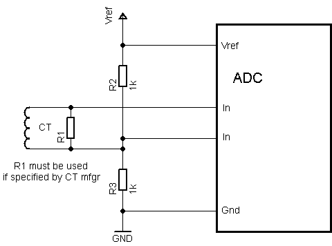
We cannot measure current directly. Firstly, we convert the secondary side current into voltage. We can use a known value of a resistor load. We measure the voltage across this known resistor. After that, we can convert this measured voltage into the current. We can use Ohm’s Law formula to convert the voltage into the current.
V=IR
I = V/R
As you can see in this circuit diagram, we use an R1 load resistor to convert current into voltage. In this circuit, a voltage divider is used, but we can also use an operational amplifier to step down the voltage across the load resistor.
How to Measure the Secondary Side Current of a CT
Now we will see how to sense AC current with the secondary side. There are many methods to measure low alternating current. You can also measure it using an AC ammeter. But if you want to perform some control operations and want to send the measured current value to another place, you have to use some kind of intelligent system.
For example, let’s say you want to create a current protection circuit and the circuit specifications are as follows:
If the current flowing through a line is greater than 100 Ampere, a control action should be performed to operate a relay.
Current > 100 Amplere , Relay = open
Otherwise if current < 100 Ampere , Relay = close
To create such an intelligent system, we can use analog and digital electronics, but it is better to opt for digital electronics considering cost constraints. In this tutorial, we will be utilizing a PIC microcontroller, specifically the PIC16F877A, to measure alternating current.
You can check about the PIC16F877A pinout and its features on this link.
Hardware components
- PIC16f877A
- CT
- An operational amplifier as a Difference amplifier
AC Current Measurement Circuit Using PIC Microcontroller
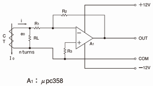
The operational amplifier acts as a voltage level-shifting circuit or difference amplifier. You can go through this guide on AC voltage measurement to understand its workings.
Difference Amplifier Circuit
To measure AC current with a PIC microcontroller, we have to use the ADC module of the PIC microcontroller. To use the ADC module, we will convert current into voltage form by using a 0.1-ohm shunt resistor across CT, and we will measure the voltage drop across the shunt resistor. This voltage drop can then be easily converted back into current. For example, the voltage drop across a 0.1-ohm shunt resistor is 8V.
Then, according to Ohm’s law.
                                                            V=IR

                                                            I=V/R

                                                          I=8/.1=8A
However, the problem is the ADC of the PIC microcontroller can never measure a voltage greater than 5 volts. Therefore, to solve this problem, we can use difference amplifiers. Because by adjusting the gain of the difference amplifier, we can reduce the voltage lower than 5 volts. The following diagram shows the circuit of CT and difference amplifier interfacing. You can use any op-amp such as LM741, TL074.
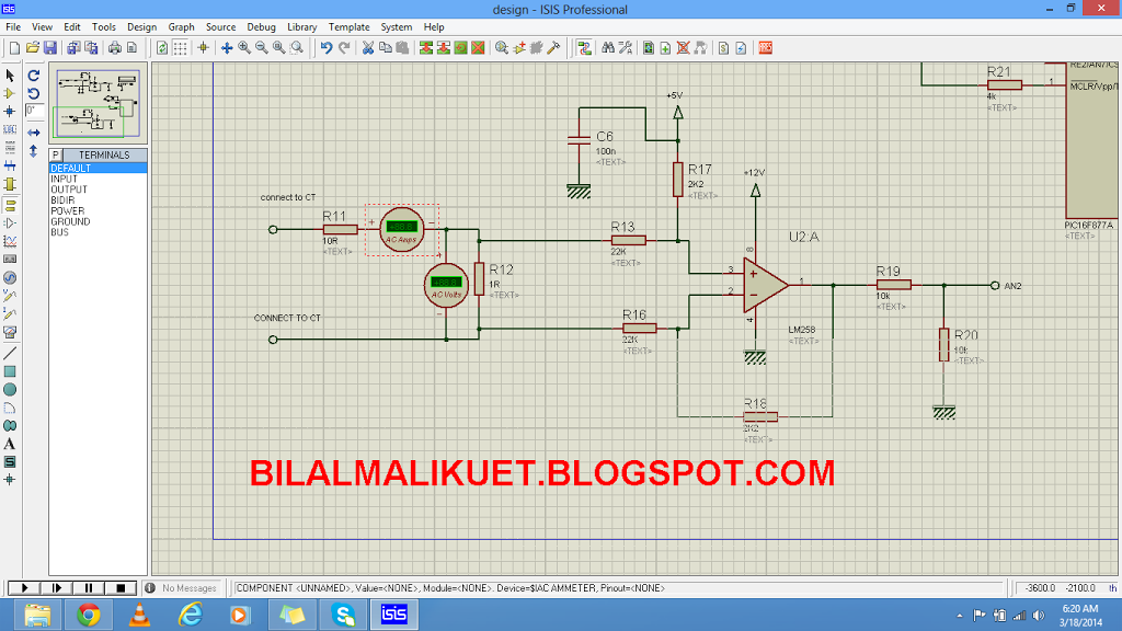
Circuit Diagram with PIC Microcontroller
This is a circuit diagram of interfacing the current sensor with a PIC microcontroller. Connect the secondary side of CT to the points shown on the schematic. After that, connect the shunt resistor in parallel with the current sensor. The difference amplifier circuit converts voltage below a 5-volt magnitude. It also shifts the level of AC voltage from the negative side to the positive side. Connect the output of the difference amplifier with RA1 or analog channel one of the PIC16F877A.
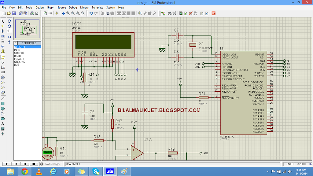
The liquid crystal display shows the values of the current. We use PORTB to connect LCD. You can go through this LCD interfacing guide.
Pic Microcontroller AC Current Measurement Code
This code is for a PIC microcontroller to measure and display the current using an analog current measurement circuit.
The code for this project is written in the MIKROC compiler. If you do not know how to use MikroC for Pic, you can refer to these tutorials:
// Define LCD connections to PORTB pins
sbit LCD_RS at RB2_bit;
sbit LCD_EN at RB3_bit;
sbit LCD_D4 at RB4_bit;
sbit LCD_D5 at RB5_bit;
sbit LCD_D6 at RB6_bit;
sbit LCD_D7 at RB7_bit;

// Set the direction of PORTB pins as digital output
sbit LCD_RS_Direction at TRISB2_bit;
sbit LCD_EN_Direction at TRISB3_bit;
sbit LCD_D4_Direction at TRISB4_bit;
sbit LCD_D5_Direction at TRISB5_bit;
sbit LCD_D6_Direction at TRISB6_bit;
sbit LCD_D7_Direction at TRISB7_bit;

float v;  // Variable to store results

// Function to read the maximum voltage across the shunt resistor
// and find the peak of AC voltage across the shunt resistor
void current_READ(void)
{
    float max;
    int i, current;
    int t[40];

    ADCON0.ADON = 1; // Enable ADC
    for(i = 0; i <= 39; i++)
    {
        v = ADC_Read(1);
        v = v * (10.0 / 1023.0);
        v = (v - 5.0);
        t[i] = v * 10;
    }

    ADCON0.ADON = 0; // Disable ADC
    max = t[0];
    for(i = 0; i <= 39; i++)
    {
        if(max < t[i])
            max = t[i];
    }
    max = max * 0.707106781; // Convert peak into RMS
    intToStr(max, txt1); // Convert integer value into a string
    Lcd_out(2, 8, txt1); // Display measured current on LCD
    delay_ms(1000);
}

void main()
{
    Lcd_Init(); // Initialize the LCD library included in MikroC for PIC
    ADCON0.ADCS0 = 1;
    ADCON0.ADCS1 = 1;
    ADCON1.ADCS2 = 1;
    ADCON0.ADON = 0;

    while(1)
    {
        Lcd_out(2, 1, "Current:"); // Display "Current" on the second line of the LCD
        current_READ(); // Call the current_READ() function to measure current
        delay_ms(1000);
    }
}
How Does Code Work?
Here is an explanation of the code line by line:
This section defines the connections between the LCD display and the microcontroller’s PORTB pins. The code configures the connections between the LCD display and the PIC microcontroller’s PORTB pins (RB2 to RB7) for data and control signals. It also sets the direction of these pins as digital outputs.
// Define LCD connections to PORTB pins
sbit LCD_RS at RB2_bit;
sbit LCD_EN at RB3_bit;
sbit LCD_D4 at RB4_bit;
sbit LCD_D5 at RB5_bit;
sbit LCD_D6 at RB6_bit;
sbit LCD_D7 at RB7_bit;
This section sets the direction of the PORTB pins as output, which allows them to communicate with the LCD display.
// Set the direction of PORTB pins as digital output
sbit LCD_RS_Direction at TRISB2_bit;
sbit LCD_EN_Direction at TRISB3_bit;
sbit LCD_D4_Direction at TRISB4_bit;
sbit LCD_D5_Direction at TRISB5_bit;
sbit LCD_D6_Direction at TRISB6_bit;
sbit LCD_D7_Direction at TRISB7_bit;
It declares two global variables: float v to store measurement results, and char txt1[] (not shown in the provided code) to store text for display on the LCD.
float v; // Variable to store resultsThis function current_READ() is responsible for reading the voltage values from the ADC and calculating the peak and RMS currents. It uses a loop to read the ADC values 40 times and stores them in an array t[]. The maximum value from the array is then taken as the peak value and converted to RMS by multiplying it with 0.707106781. Finally, the measured current value is converted to a string and displayed on the LCD.
// Function to read the maximum voltage across the shunt resistor
// and find the peak of AC voltage across the shunt resistor
void current_READ(void)
{
    float max;
    int i, current;
    int t[40];

    ADCON0.ADON = 1; // Enable ADC
    for(i = 0; i <= 39; i++)
    {
        v = ADC_Read(1);
        v = v * (10.0 / 1023.0);
        v = (v - 5.0);
        t[i] = v * 10;
    }

    ADCON0.ADON = 0; // Disable ADC
    max = t[0];
    for(i = 0; i <= 39; i++)
    {
        if(max < t[i])
            max = t[i];
    }
    max = max * 0.707106781; // Convert peak into RMS
    intToStr(max, txt1); // Convert integer value into a string
    Lcd_out(2, 8, txt1); // Display measured current on LCD
    delay_ms(1000);
}
The main() function is the entry point of the code. It initializes the LCD display using Lcd_Init() a function. The ADC conversion clock is set and the ADC module is disabled initially. Inside the infinite while loop, the text “Current:” is displayed on the LCD, and the current_READ() function is called to measure and display the current value. There is a delay of 1 second before each iteration of the loop.
void main()
{
    Lcd_Init(); // Initialize the LCD library included in MikroC for PIC
    ADCON0.ADCS0 = 1;
    ADCON0.ADCS1 = 1;
    ADCON1.ADCS2 = 1;
    ADCON0.ADON = 0;

    while(1)
    {
        Lcd_out(2, 1, "Current:"); // Display "Current" on the second line of the LCD
        current_READ(); // Call the current_READ() function to measure current
        delay_ms(1000);
    }
}
The code continuously measures and displays the RMS current value on an LCD screen. It assumes that an external circuit with a shunt resistor and appropriate signal conditioning provides an AC voltage signal to be measured by the PIC microcontroller’s ADC. The code displays the measured current value on the LCD for monitoring purposes.
Video demo:
Conclusion
In conclusion, this article has provided a comprehensive guide to designing an AC ammeter using a PIC microcontroller. The tutorial covered the fundamentals of current transformers, the process of interfacing a current transformer with the PIC16F877A microcontroller, and writing the necessary code for AC current measurement. By following the instructions and understanding the concepts presented, readers now have the knowledge and skills to create their own AC ammeter for their PIC microcontroller projects.
V= adc_read(0);
V= v*( 10.0 /1023.0);
V= v-5.0 ;
V= v* 10 ;
Pls kindly explain thanks
v= ADC_Read(1);
v =v*(10.0/1023.0);
v=(v-5.0);
t[i]=v*10;
Please explain the equation from where it comes ??
Hi
Thanx for this blog
My project is to measure current of the output of the ups (solar and ac utility joined together) and according to this measurement i will close or open switch
What i will add to the code
جزاك الله خيرا
مرحبا استاذ وائل جزاك الله كل خير ، ان امكن ولديك معلومات بخصوص حساب التيار والقوات والحراره والضوء في pic اتمنى ان تساعدني في ذلك بارك الله فيك 🌹✨
..i want to read power factor of 50Hz 220V ac…can you help me wiith it??
I want to know if the difference amplifier can be replaced by a voltage divider to reduce the voltage below 5v?
Nice job, but can I connect this 1 ohm burden to any CT? Because my CT datasheet recommends, 125 ohms. I am using 20A:1A CT.
how to apply current ratio formula in program? if it is 20A:1A
Hi
is not working……
what is not working ?
donne le schema coomplet miseur de courant et tension avec pic16f877a
Hi,
This current measurement meter can i check battery current?
yes you can use
hi
Why multiplying 10
V= v* 10 ;
What is CT?
current transformer
wait for 2 two days and check your email
hi, thanx for the blog. I need helpon how to monitor current drawn by a 1Hp submersible pump using a PIC uC. its a single phase pump 220-240Hz. I want to monitor the current drawn so that I can protect the pump from dry running and from overload.
thanks in advance
hi can you explain the code
v= ADC_Read(1);
v =v*(10.0/1023.0);
v=(v-5.0);
t[i]=v*10;
i do not understand the code
please send me code and simulation thanks :))
Hello Bilal,
I have been given a project recently to measure primary current 10-300A using Pic 16f1787 & 3.6V battery.
My CT is having turns ratio of 2000.It means my secondary current will be between 0.005 to 0.15A rms.
I am told to use 3.6V lithium battery for powering the circuit. Your article was a bit relief for me.By reading your article I have understood that I can use difference amplifier to rectify the signal.please guide me.
Can you send me the flowchart of your code?
can i put clamp meter ??
in the place of CT ???
i do appliciate it bro
what kind of circuit can replace CT
i am a 2nd year b.tech student don’t know how to calculate primary current according to CT current ratio by using current ration formula & on’t know high level of microcontrollers programming.please help me
hi , why when i have in input 1A , it give me in lcd 0A ?
Hello, how can I use decimal values (in this case 0.707) in MikroC? Thanks in advance
IT LOOK LIKE YOU ARE NOT HELPING , NON OF YOUR EXAMPLE CODE IS NOT COMPLETE
nice project work, i doing same work but in this project i want to measure ac source of 220v 20A, what modification i should do,
can you explain where number 707106781 from?;
Hi i am required to do this design at my school but the is i dont understand its schematic diagram.
why not just adjust the gain instead of connecting an offset resistor
v= ADC_Read(1);
v =v*(10.0/1023.0); //reference has been shifted from 5v to 10v
v=(v-5.0); // offset voltage is 5v
t[i]=v*10; //inverse of (2.2k/22k) is
}
Why did you choose to go with the diff amp, which is a lot more complex? Why didnt you just use the simple voltage divider? Is there any particular advantage of the diff amp method over te divider?
WOULD YOU LIKE TO HELP ME BY SENDING HOW TO CONTROL POWER THEFT WHO STOLE POWER BEFORE ENERGY METER . I NEED TO DO PROJECT ABOUT THUS .SO WOULD YOU LIKE TO HELP ME BY SENDING MICRO C CODE ABOUT IT
can you write a pic software for pwm output?
I have very simple hardware ..
hi Sir, i wish to know more regarding the purchase of the code + simulation. thanks
Please pardon me for my ignorance. As we all know that ADC of mcu can take input as voltage and current measurement can be done by I=(V/R) where R=shunt resistor. In this code I didn’t find any thing like dividing voltage by resistor value.
I also have some difficulty in understanding this piece of code
v= ADC_Read(1);
v =v*(10.0/1023.0); // aren’t we supposed to use 5 since it can tolerate 5
v=(v-5.0); // why we subtracting by 5 here
t[i]=v*10; // is it for applying 100:10 ratio ?
If some made me understand that would be helpful.
Thank you.
The code is giving error like undefined identifiers for AD0N0.ADON & many more plz help me sir reply as soon as as possible on email plz sir
You are a wrong microcontroller while designing a project.
what is wrong bcz iam using mickro c pic compiler using pic 16f877a microcontroller. what is header file for it
You need to include libraries from the library manager
Hi bro, can you please send me the complete circuit with CT connected and the complete code with formula applied? I will be really grateful bilal bhai.
wahab3834@gmail.com
V= adc_read(0);
V= v*( 10.0 /1023.0);
V= v-5.0 ;
V= v* 10 ;
Pls kindly explain thanks
Hi bro, can you please send me the complete circuit with CT connected and the complete code with formula applied? I will be really grateful bilal
ch.elbachiri123@gmail.com
Can anyone describe design steps of opamp circuit section ?
give me hex file of ac current measurement using pic microcontroller