In this modern world, Analog Electronics devices are becoming less popular and digital electronics components are becoming more advanced and popular day by day. Home devices control system is also an example of modernized digital world. People are using cellular mobile phone network to communicate each other. GSM modules are basic elements of these phone networks. GSM stand for global system of mobile communication. It is also used in many electronics projects among engineering students and also very popular in industry. GSM based projects are used to control devices through mobile from remote locations. For example you want to control any machine from remote locations using your mobile phone, Can you do it? The answer to this question is yes. We can easily turn on and turn off devices using GSM modules and mobile phones. By using above concepts, home devices control system is designed to control home devices from mobile phone.
How to use GSM module for home devices control system?
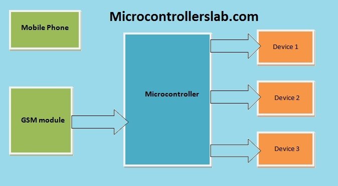
The basic concepts of this project is to turn on or turn off home devices like fans, lights etc through mobile phone. So SMS is used for this purpose. SMS communicates information between two devices. GSM module is kind of mobile phone. It have built in subscribers identity module i.e. SIM. GSM module is connected with microcontroller. GSM module interfacing with microcontroller is not difficult task. Control devices are also connected with microcontroller. I will explain it in later part of this article. Microcontroller receives information from GSM which is sent from mobile. According to information received by microcontroller, it turns on or turns off home devices. Basic block diagram of home devices control system is shown below.
Components of home devices control system
Following are the main components used in home devices control system.

- GSM module: It is one of the main components of this project. It is interface with microcontroller which receives information from GSM and after reading the information; it turns on or turn off devices with the help of relay driver circuit connected with it. Serial communication is used for interfacing between two devices. SIM 300 modules are operating on 900MHz and 1900MHz frequencies.
- AT mega 16 Microcontroller: Microcontroller is a kind of minicomputer which is used to perform small function of computers. It is basically a complete processor integrated on a small chip but it has less memory, less speed and processing speed than high speed processors used in computers. But microcontrollers are designed for specific applications in embedded system projects. They are used in many embedded systems applications. The major difference between microprocessor and microcontroller are size, cost and processing speed. In this project microcontroller is main components, which receives information in the form of message and after reading message it make decision either to turn on or turn off device through relay driver circuit.
- Liquid crystal display: 16*2 LCD is used. It has 14 data pins and 2 pins for LED lights. LCD is used to display status of home devices control system. The main objective of LCD in home devices control system is to display on screen which device is on or which device is off. So you should know how to interface LCD with microcontroller.
- Relays: Electromechanical relays are used as a switch to provide isolation between two circuits. Relays are used to isolated high voltage devices from microcontroller. Because It operated only on 5 volt. Above 5 volt microcontroller may burn completely. So relays are used to isolate them. Microcontroller energizes the relays by providing those signals through transistor. So It is very important to know how to interface relay with microcontroller. There are many types of relays available in market but we are using single pole double through relay.
- ULN2003 relay driver circuit: Microcontrollers cannot provide current more than 3mA from output pins. So we need to use a method to increase current value of microcontroller signal which is given to relays. Relay driver circuits are used for this purpose. ULN2003 relay driver circuit is dedicated IC design for such applications. We can also design using transistor but it is better to use dedicated IC for this purpose.
| COMPONENT | MODEL | QUANTITY |
| GSM modem | SIM 300 | 1 |
| Microcontroller | ATMEGA 168 | 1 |
| Interfacing device | ULN 2803 | 1 |
| Relay | JIH JIK | 4 |
| LCD | HD44780U | 1 |
| LED | 6 | |
| Variable resistance | 1 | |
| Voltage Regulator | LM 7805 | 1 |
| Diode | IN 4007 | 2 |
| Resistance | 1Kohm | 6 |
| Resistance | 10Kohm | 1 |
| Crystal oscillator(10 MHz) | 1 | |
| Ceramic capacitor | 104/AEC | 1 |
| Ceramic capacitor | 33/AEC | 2 |
| Connector | 9 | |
| Connecting wires | ||
| Relay | JQC-3FC | 4 |
Circuit diagram of GSM based home devices control system
Basic block diagram of home devices control system is shown below.
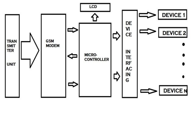
Transmit unit at the most left side is mobile phone which send information through shot messaging service i.e. SMS to GSM modem. GSM modem receives information and transfer this information to microcontroller through serial communication. Serial communication is type of communication in which data transfer bit by bit to microcontroller. Unlike, parallel communication which transfer all bits at a time. Microcontroller receives data and makes decision according to program written inside it and after making decisions microcontroller energize or de-energize relays through relay driver circuits. In other words, it turns on or turns off home devices. This is how home devices control system works.

Applications of home devices control system
There are numerous applications of home devices control system. Some of the important application are given below:
- It can be used for home automation system
- It can be used for remote locations devices control.
- Security system for home and industry
- Solar power automatic irrigation system
- It can also be used to save energy in countries which are victims of energy short falls and load shedding.
Code of home devices control system
To write code for this project, you should know how to interface GSM modem with microcontroller? How to receive SMS? How to send SMS using GSM Modem and microcontroller? How to interface relays and LCD? I think, if you know how to do above tasks, you can easily write code for this project. I recommend you to write your own for this project, but if you need code for this project contact me through email or comment on this post. Thanks keep sharing this post with others. Remember code is not free of cost.
I am interested in this project,i need your help…
code is not free of cost. If you want to purchase code contact me at microcontrollerslabhub@gmail.com
Please send me code on mayurmakwana100@gmail.com
Pls I need your help on dis project , I am new to Gsm module . My email is anuoluwapoadeniji@gmail.com
Pic using mikroc complier
I will be grateful if my request is granted
you can contact me at microcontrollerslabhub@gmail.com if you need my project service
Plz send gsm base home device control
am interested in this idea and am doing mini project in this subject.
how the gsm modem know the status of device and send notification to user?
how to interface gsm with pic16f877A and hown to load C code to pic?
pls attach this answer to my email dawitbelachew457@gmail.com
thanks.
Interested to make this project , can you provide the code, can you mail of provide link fothe code I will able to downlaod
how to interface gsm with 8051
plz send the program code for pic16f877 & gsm program code
Good luck
plz send the program code for pic16f877 & gsm program code
contact us at microcontrollerslabhub@gmail.com
Hello, I want code for home automation using gsm also i want interface PIR sensor for this project.
plizzzz i want a code in twos day ..
i will play
Pliz send code for this project. ..
please send code of gsm based home automation
Please help me i need this source code i beg you help me
Can you help me send the code to mynameisbirly@gmail.com
am interested in the above project kindly assist
Hi
The GSM module, do i need a service to make it work?
Thanks
Relay control with Arduino sim800l is very popular and useful. In our place, there are frequent power outages. If possible, share it with electricity and water. Please let me know when there is a power outage. I am from the second place. Thank you.