In this Arduino project, we will show you how to send data from a GSM module to a web server using Arduino. This article will help you send data to a server using GPRS data of GSM module. You can control anything from a server and send any type of data to a server using GSM module using GPRS data of your mobile phone network. You can also do the same task with the help esp826 wifi module and ethernet shield.
This is an IoT-based project in which we will send data from SIM900A GSM / GPS module to web server using Arduino. We have already posted an article on sending data to the server using an Arduino. In this embedded systems based project, We enter data using 4×4 keypad and also display on 16×2 LCD in real time. Data can be of any type numeric, alphabetic or a special character. A web server which is used to receive data is created on Spark fun website which can be publicly accessed and used.

Sending Data from GSM module to a web server Overview
We will require the following components for this project.

Required Components:
- Arduino Uno: We will use Arduino due to its easy use. It also provides several digital pins to interface with the LCD, GSM module, and keypad at the same time. It is very friendly when you prototyping any project.
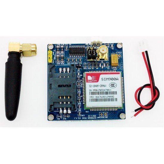
- GSM SIM900A: SIM900A GSM Module is the smallest and cheapest module for GPRS/GSM communication. The module offers GPRS/GSM technology for communication with the uses of a mobile sim. It uses a 900 and 1800MHz frequency band and allows users to receive/send mobile calls and SMS. We can send SMS, data, Voice, and Fax using this module. Its operating voltages range is 3.2 to 4.8V. It draws only 1.0mA in sleep mode. Its Operating temperature range is -40°C to +85 °C. Note use a power supply which can supply up to 1 amp. You can check this article to know, how to interface a GSM module with Arduino.
- External 5 volt supply: 5 volt dc supply is required to power the GSM module.
- 16×2 LCD: 16×2 LCD is used to display 16 characters in two lines. It is easy to interface with Arduino due to its available library. It also operates on the same voltages of Arduino Uno. In this project, this LCD is used to display different messages. A 10k potentiometer is used to control the contrast of the display.
- 4×4 Keypad: It consists of 4 rows and 4 columns. It contains 16 buttons which we can define as our requirement in the code. The following keypad is used in this project:

Working
In this project, Arduino Uno is used as the brain of our circuit.
You can view the operations constituting this project in the block diagram below.

First of all, we will enter text using the 4×4 keypad. The text will be displayed on 16×2 LCD in real time.
We will program our project in such a way that we will be able to enter both numerical and alphabets/characters using the 4×4 keypad. The figure above shows the keypad configuration we will use in this project. For example if we press the key 3 once then it will enter D. If we press it again, then it will enter E. If we press it again, then it will enter F.
After writing the text, we will press D button on the keypad to send the data to the Spark Fun web server. The GSM module will connect to the web server by using the information defined in the code such as public and private keys. It will send the data on the web server which we can check by opening the web server. The data can be of any type such as numeric, alphabetic or special character. The only disadvantage is that spark fun only provides 50MB of data which is not enough if you want to use it regularly.
Connection Diagram for sending data to a web server using Arduino
In this section, we will explain the connections of the various components specified above with Arduino Uno to form this project.
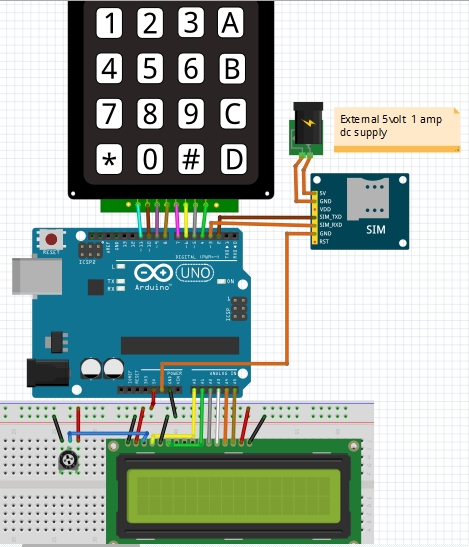
Let us discuss them one by one.
Arduino with SIM900A GSM Module
The communication between Arduino and GSM module is serial. Connect the Tx pin of GSM module with Pin 2 of Arduino and Rx pin of GSM module with Pin 3 of Arduino. Connect VCC pin to external 5v supply which can deliver up to 1 amp and GND pin with GND of both the power supply and Arduino.
Arduino with 16×2 LCD
We will use a 16×2 LCD in our project to display different messages. To connect a 16×2 LCD with Arduino we will require an additional 10k potentiometer as well.
We have a dedicated tutorial regarding interfacing 16×2 LCD display with Arduino with some example sketches. Have a look at it before proceeding further for a better understanding of the LCD.
Recommended Reading: 16×2 LCD Interfacing with Arduino – Explained with Example Codes
There are two types of pins on the whole 16×2 LCD module. Some pins are used to send to 16×2 LCD and some are command pins. In other words, every pin has a role in controlling a single pixel on the display.16 x 2 LCD has sixteen columns and two rows. That means, it can display sixteen characters per row and it has two such rows.
Pinout
The diagram shows the pin configuration of a 16×2 LCD display. It has sixteen pins.

- D0 – D7: Pin number 7-14 are data bus lines that are used to send data from Arduino which you want to display on LCD. With these 8 data lines, data can be transferred either in an 8-bit format or in a 4-bit format. In a 4-bit format, only upper four bits (D4-D7) are used to send data from Arduino to LCD. The full byte is transmitted in two successive transmissions. A 4-bit format is used to save GPIO pins of Arduino. Because fewer GPIO pins of Arduino will be required to transfer data.
- Contrast Select (VEE): It will help to control the contrast of PIXELS according to the 16X2 LCD light.
- RS: This pin is known as a register select pin. It helps to toggle the command/data register.
- R/W: The signal on this pin will decide whether it is going to read from LCD or write on it.
- EN: Enable pin will help to transfer the instruction from the data pins and another command pin to the LCD. It act as permission to internal registers.
- VSS: It’s a ground pin for common grounds.
- VCC: The power pin will use for voltage input to the 16X2 LCD.
Arduino connections with 16×2 LCD
We are using the following connections as described below. Refer to the schematic diagram to have a clearer idea of the connections.
| 16×2 LCD | Arduino |
|---|---|
| D4 – D7 | Pin A2, A3, A4, A5 |
| Enable | Pin A1 |
| RS | Pin A0 |
| RW | GND |
| VEE | 10k POT (Middle Leg) |
| VSS | GND |
| VCC | +5V |
| LED+ | +5V |
| LED- | GND |
We have an Arduino library for easy communication between LCDs called the LiquidCrystal library. It is an inbuilt library by Arduino Adafruit version.
Arduino with 4×4 Keypad
Keypads consist of push buttons arranged in row and column pattern. That means if we take an example of a 4×4 keypad, it will internally consist of 16 push buttons. To save microcontroller pins, keypads are arranged in the form matrix of rows and columns. For instance, a 4×4 keypad is arranged into a matrix of four rows and four columns. By using this pattern, we will need only 8 GPIO pins of Arduino.
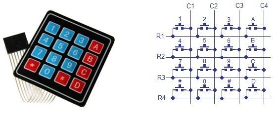
The status of each key/switch is determined by Scanning the rows or columns. The column pins (Col 1–Col4) are connected to the microcontroller as the inputs pins and the rows pins (Row 1–Row 4) are connected to the output pins of the microcontroller. Normally, all the column pins are pulled high by internal or external pull up resistors. Now we can read the status of each switch through scanning.
The following figure shows the pinout of a 4×4 keypad.
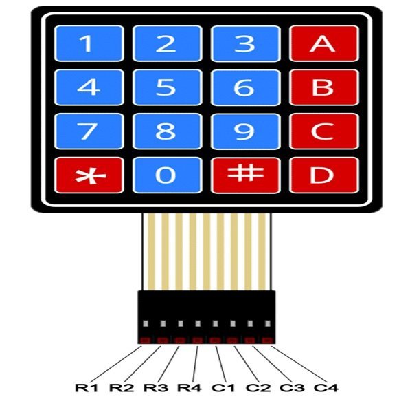
The output connector provides output pins for rows and columns. The first four pins from the left are rows and the last four pins from the right are the columns. To sense the state of each pushbutton from a specific location of a row and a column, we will use digital pins of Arduino.
4×4 Keypad Connections with Arduino Uno:
These are the Arduino pins that we will use (starting from left):
- Keypad pin 1 (R1) to Arduino pin Pin 11.
- Keypad pin 2 (R2) to Arduino pin Pin 10.
- Keypad pin 3 (R3) to Arduino pin Pin 9.
- Keypad pin 4 (R4) to Arduino pin Pin 8.
- Keypad pin 5 (C1) to Arduino pin Pin 7.
- Keypad pin 6 (C2) to Arduino pin Pin 6.
- Keypad pin 7 (C3) to Arduino pin Pin 5.
- Keypad pin 8 (C4) to Arduino pin Pin 4.
Create Web server on Spark Fun Website
Visit the Spark Fun website. Go to the data section.

Click on the following option: Create data stream on Spark fun
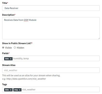
Fill the required information and click on save.
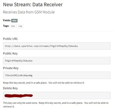
Now you will see the following Links: Save the keys for the future use.

Send Data to server using GSM module Arduino Code
We will use Arduino IDE to program our Arduino board.
Install Keypad Library
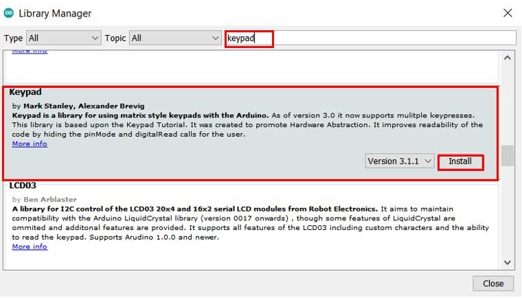
We will use the Keypad library by Mark Stanley and Alexander Brevig. This library will make it easy to work with the 4×4 keypad.
We will use the Library Manager in our Arduino IDE to install the latest version of the library. Open your Arduino IDE and go to Sketch > Include Libraries > Manage Libraries. Type ‘keypad’ in the search bar and install the latest version.
Arduino Sketch
Open your Arduino IDE and go to File > New to open a new file. Copy the code given below in that file and save it.
#include <SoftwareSerial.h> // serial software library for interfacing gsm module
#include<LiquidCrystal.h> // LCD library for interfacing LCD
#include <Keypad.h> // keypad library for interfacing keypad

SoftwareSerial Serial1(2, 3); // RX, TX // connect gsm Tx at D2 and Rx at D3
LiquidCrystal lcd(14, 15, 16, 17, 18, 19); // connect rs,en,d4,d5,d6,d7 respectevely

String pvtKey = "wY9DPG5vzpH99KNrNkx2"; // private key for posting data to sparkfun
String publicKey = "w5nXxM6rp0tww5YVYg3G"; // public key for open page of sparkfun
String url = "";
String ip = "\"data.sparkfun.com\""; // sparkfun server ip or url
int port = 80; // sparkfun server port
String SendCmd = "AT+CIPSEND="; // sending number of byte command
String Start = "AT+CIPSTART=\"TCP\""; // TCPIP start command

String instr = "";
String str_sms = "";
String str1 = "";
int i = 0, temp = 0;

const byte ROWS = 4; //four rows
const byte COLS = 4; //four columns
int x = 0;
int y = 0;
int n = 0;
int minValue = 0;
int maxValue = 0;
char keyPress = 0;
int keyPressTime = 100;
String msg = "";
char hexaKeys[ROWS][COLS] =
{
  {'1', '2', '3', 'A'},
  {'4', '5', '6', 'B'},
  {'7', '8', '9', 'C'},
  {'*', '0', '#', 'D'}
};

byte rowPins[ROWS] = {11, 10, 9, 8}; //connect to the row pinouts of the keypad
byte colPins[COLS] = {7, 6, 5, 4}; //connect to the column pinouts of the keypad

Keypad customKeypad = Keypad( makeKeymap(hexaKeys), rowPins, colPins, ROWS, COLS);

String alpha = "1!@_$%?ABC2DEF3GHI4JKL5MNO6PQRS7TUV8WXYZ9* 0#";

void setup()
{
  Serial1.begin(9600); // init serial for GSM
  lcd.begin(16, 2); // init LCD
  lcd.print("MICROCONTROLLERS");
  lcd.setCursor(0, 1);
  lcd.print(" LAB ");
  delay(2000);

  lcd.clear();
  lcd.print("Sending Data ");
  lcd.setCursor(0, 1);
  lcd.print("to Server");
  delay(2000);
  lcd.clear();

  lcd.print("Initializing GSM");
  initGSM(); // init GSM module
  lcd.clear();
  lcd.print("Initializing GPRS");
  initGPRS(); // init GPRS in GSM Module
  lcd.clear();
  lcd.print("System Ready");
  delay(2000);
}
void loop()
{
  int n = 0;
  lcd.clear();
  lcd.noCursor();
  while (1)
  {
    lcd.cursor();
    char key = customKeypad.getKey();
    if (key == '1')
      getkey(0, 6, key);
    if (key == '2')
      getkey(7, 10, key);
    else if (key == '3')
      getkey(11, 14, key);
    else if (key == '4')
      getkey(15, 18, key);
    else if (key == '5')
      getkey(19, 22, key);
    else if (key == '6')
      getkey(23, 26, key);
    else if (key == '7')
      getkey(27, 31, key);
    else if (key == '8')
      getkey(32, 35, key);
    else if (key == '9')
      getkey(36, 40, key);
    else if (key == '*')
      getkey(41, 41, key);
    else if (key == '0')
      getkey(42, 43, key);
    else if (key == '#')
      getkey(44, 44, key);

    else if (key == 'C')
    {
      x--;
      lcd.setCursor(x, y);
      lcd.print(" ");
      n--;
      msg[n] = ' ';
      lcd.setCursor(x, y);
    }
    else if (key == 'D')
    {
      lcd.clear();
      lcd.noBlink();
      lcd.print("Data Sending");
      lcd.setCursor(0, 1);
      lcd.print("To Server");
      url = "GET /input/";
      url += publicKey;
      url += "?private_key=";
      url += pvtKey;
      url += "&log=";
      url += msg;
      url += " HTTP/1.0\r\n\r\n";
      String svr = Start + "," + ip + "," + port;
      delay(1000);
      connectGSM(svr, "CONNECT");
      delay(1000);
      int len = url.length();
      String str = "";
      str = SendCmd + len;
      sendToServer(str);
      Serial1.print(url);
      delay(1000);
      Serial1.write(0x1A);
      delay(1000);
      lcd.clear();
      lcd_status();
      // clearmsg();
      n = 0;
      i = 0;
      x = 0;
      y = 0;
      msg = "";
    }
  }
}
void getkey(int minValue, int maxValue, char keyPress)
{
  int ch = minValue;
  int pressed = 1;
  char key = keyPress;
  lcd.noBlink();
  for (int i = 0; i < keyPressTime; i++)
  {
    if (key == keyPress)
    {
      lcd.setCursor(x, y);
      lcd.print(alpha[ch]);
      ch++;
      if (ch > maxValue)
        ch = minValue;
      i = 0;
    }
    key = customKeypad.getKey();
    delay(10);
  }
  if (pressed)
  {
    x++;
    msg += alpha[ch - 1];
    n++;
    if (x > 15)
    {
      x = 0;
      y = 1;
    }
  }
  pressed = 0;
  lcd.blink();
}
void lcd_status()
{
  lcd.clear();
  lcd.print("Data Sent to");
  lcd.setCursor(0, 1);
  lcd.print("Server");
  delay(2000);
  lcd.clear();
}
void sendToServer(String str)
{
  Serial1.println(str);
  delay(1000);
}
void initGSM()
{
  connectGSM("AT", "OK");
  connectGSM("ATE1", "OK");
  connectGSM("AT+CPIN?", "READY");
}
void initGPRS()
{
  connectGSM("AT+CIPSHUT", "OK");
  connectGSM("AT+CGATT=1", "OK");
  connectGSM("AT+CSTT=\"airtelgprs.com\",\"\",\"\"", "OK");
  connectGSM("AT+CIICR", "OK");
  delay(1000);
  Serial1.println("AT+CIFSR");
  delay(1000);
}
void connectGSM (String cmd, char *res)
{
  while (1)
  {
    Serial.println(cmd);
    Serial1.println(cmd);
    delay(500);
    while (Serial1.available() > 0)
    {
      if (Serial1.find(res))
      {
        delay(1000);
        return;
      }
    }
    delay(1000);
  }
}
/*
  Public URL
  http://data.sparkfun.com/streams/w5nXxM6rp0tww5YVYg3G
  Public Key
  w5nXxM6rp0tww5YVYg3G
  Private Key
  wY9DPG5vzpH99KNrNkx2
  Keep this key secret, and in a safe place. You will not be able to retrieve it.
  Delete Key
  xxxxxxxxxxxxx
  This key can only be used once. Keep this key secret, and in a safe place. You will not be able to retrieve it.
  Logging using query string parameters
  Format:
  http://data.sparkfun.com/input/[publicKey]?private_key=[privateKey]&log=[value]
  Example:
  http://data.sparkfun.com/input/w5nXxM6rp0tww5YVYg3G?private_key=wY9DPG5vzpH99KNrNkx2&log=22.21
*/
How the Code Works?
We will start by including the required libraries for this project.
#include <SoftwareSerial.h> // serial software library for interfacing gsm module
#include<LiquidCrystal.h> // LCD library for interfacing LCD
#include <Keypad.h> // keypad library for interfacing keypad
The following line defines the serial communication Tx pin at Arduino pin 2 and Rx at Arduino pin 3.
SoftwareSerial Serial1(2, 3); // RX, TX // connect gsm Tx at D2 and Rx at D3Next, we declare the Arduino pins that are connected with the LCD. To define connections, we use the following line of code. This line creates a LiquidCrystal object and lcd is a name of the object that we are going to use to call LCD functions. You can also use any other name.
LiquidCrystal lcd(rs, en, d4, d5, d6, d7)In our case, the pins are 14, 15, 16, 17, 18, and 19 respectively.
LiquidCrystal lcd(14, 15, 16, 17, 18, 19); Declare the private and public key that we obtained from SparkFun server. This will be used to send data to the server.
String pvtKey = "wY9DPG5vzpH99KNrNkx2"; // private key for posting data to sparkfun
String publicKey = "w5nXxM6rp0tww5YVYg3G"; // public key for open page of sparkfun
String url = "";
String ip = "\"data.sparkfun.com\""; // sparkfun server ip or url
int port = 80; // sparkfun server portAT+CIPSEND: This command is responsible to send the data over the TCP/UDP connection.
AT+CIPSTART: This command is used to start a TCP/UDP connection.
String SendCmd = "AT+CIPSEND="; // sending number of byte command
String Start = "AT+CIPSTART=\"TCP\""; // TCPIP start command
The following lines of code are for the keypad keys defining the rows, columns, the minimum/maximum values and the array matrix for the keys.
const byte ROWS = 4; //four rows
const byte COLS = 4; //four columns
int x = 0;
int y = 0;
int n = 0;
int minValue = 0;
int maxValue = 0;
char keyPress = 0;
int keyPressTime = 100;
String msg = "";
char hexaKeys[ROWS][COLS] =
{
  {'1', '2', '3', 'A'},
  {'4', '5', '6', 'B'},
  {'7', '8', '9', 'C'},
  {'*', '0', '#', 'D'}
};

byte rowPins[ROWS] = {11, 10, 9, 8}; //connect to the row pinouts of the keypad
byte colPins[COLS] = {7, 6, 5, 4}; //connect to the column pinouts of the keypad
Moreover, we will create an instance of Keypad called ‘customKeypad.’
Keypad customKeypad = Keypad( makeKeymap(hexaKeys), rowPins, colPins, ROWS, COLS);getkey()
We will use the getkey() function to input alphabets. It takes in three parameters. The minimum value, the maximum value and the key which is pressed. We will use the 4×4 keypad to input alphanumeric values. So the keypad will be capable of inputting not only numbers but alphabets as well. The function given below will help us input the alphabets.
void getkey(int minValue, int maxValue, char keyPress)
{
  int ch = minValue;
  int pressed = 1;
  char key = keyPress;
  lcd.noBlink();
  for (int i = 0; i < keyPressTime; i++)
  {
    if (key == keyPress)
    {
      lcd.setCursor(x, y);
      lcd.print(alpha[ch]);
      ch++;
      if (ch > maxValue)
        ch = minValue;
      i = 0;
    }
    key = customKeypad.getKey();
    delay(10);
  }
  if (pressed)
  {
    x++;
    msg += alpha[ch - 1];
    n++;
    if (x > 15)
    {
      x = 0;
      y = 1;
    }
  }
  pressed = 0;
  lcd.blink();
}
initGSM()
The initGSM() function initializes the GSM module using the connectGSM() and passing AT commands as first parameter and the response as the second parameter inside it.
AT: This type of command is used to test the startup function of the module. The response would be ok, against this command if everything is ok.
ATE1: This command will be responsible for enabling the echo.
AT+CPIN?: This command will be used to check if the SIM card is present in the GSM module or not.
void initGSM()
{
  connectGSM("AT", "OK");
  connectGSM("ATE1", "OK");
  connectGSM("AT+CPIN?", "READY");
}
initGPRS()
The initGPRS() function initializes the GPRS using the connectGSM() and passing AT commands as first parameter and the response as the second parameter inside it.
AT+CIPSHUT: This command will disconnect connection if present (close the TCP port explicitly)
AT+CGATT=1: This command will attach the terminal to the GPRS service.
AT+CSTT=”APN”, “USER”, “PWD”: This command will set the Access Point Name, User name and Password for the PDP connection. Use access point name of your SIM card provider.
AT+CIICR: This command brings up the GPRS/CSD call on the configuration that was previously set by the AT+CSTT command.
AT+CIFSR: This command obtains the local IP address.
void initGPRS()
{
  connectGSM("AT+CIPSHUT", "OK");
  connectGSM("AT+CGATT=1", "OK");
  connectGSM("AT+CSTT=\"airtelgprs.com\",\"\",\"\"", "OK");
  connectGSM("AT+CIICR", "OK");
  delay(1000);
  Serial1.println("AT+CIFSR");
  delay(1000);
}
connectGSM()
The connectGSM() function will be used to initialize the GPRS and the GSM module.
void connectGSM (String cmd, char *res)
{
  while (1)
  {
    Serial.println(cmd);
    Serial1.println(cmd);
    delay(500);
    while (Serial1.available() > 0)
    {
      if (Serial1.find(res))
      {
        delay(1000);
        return;
      }
    }
    delay(1000);
  }
}
setup()
Inside the setup() function we first initialize the serial for GSM at a baud rate of 9600. We also initialize the LCD and print relevant messages on the display after a delay of 2 seconds. The initGSM() and initGPRS() functions are also called that initialize the GSM module and GPRS respectively.
void setup()
{
  Serial1.begin(9600); // init serial for GSM
  lcd.begin(16, 2); // init LCD
  lcd.print("MICROCONTROLLERS");
  lcd.setCursor(0, 1);
  lcd.print(" LAB ");
  delay(2000);

  lcd.clear();
  lcd.print("Sending Data ");
  lcd.setCursor(0, 1);
  lcd.print("to Server");
  delay(2000);
  lcd.clear();

  lcd.print("Initializing GSM");
  initGSM(); // init GSM module
  lcd.clear();
  lcd.print("Initializing GPRS");
  initGPRS(); // init GPRS in GSM Module
  lcd.clear();
  lcd.print("System Ready");
  delay(2000);
}
loop()
Inside the loop() function we will send alphanumerical data through the GSM module to SparkFun server. We will use a series of if-else if statements to check which key was entered and thus, we will accordingly input the characters using the getkey() function.
void loop()
{
  int n = 0;
  lcd.clear();
  lcd.noCursor();
  while (1)
  {
    lcd.cursor();
    char key = customKeypad.getKey();
    if (key == '1')
      getkey(0, 6, key);
    if (key == '2')
      getkey(7, 10, key);
    else if (key == '3')
      getkey(11, 14, key);
    else if (key == '4')
      getkey(15, 18, key);
    else if (key == '5')
      getkey(19, 22, key);
    else if (key == '6')
      getkey(23, 26, key);
    else if (key == '7')
      getkey(27, 31, key);
    else if (key == '8')
      getkey(32, 35, key);
    else if (key == '9')
      getkey(36, 40, key);
    else if (key == '*')
      getkey(41, 41, key);
    else if (key == '0')
      getkey(42, 43, key);
    else if (key == '#')
      getkey(44, 44, key);

    else if (key == 'C')
    {
      x--;
      lcd.setCursor(x, y);
      lcd.print(" ");
      n--;
      msg[n] = ' ';
      lcd.setCursor(x, y);
    }
    else if (key == 'D')
    {
      lcd.clear();
      lcd.noBlink();
      lcd.print("Data Sending");
      lcd.setCursor(0, 1);
      lcd.print("To Server");
      url = "GET /input/";
      url += publicKey;
      url += "?private_key=";
      url += pvtKey;
      url += "&log=";
      url += msg;
      url += " HTTP/1.0\r\n\r\n";
      String svr = Start + "," + ip + "," + port;
      delay(1000);
      connectGSM(svr, "CONNECT");
      delay(1000);
      int len = url.length();
      String str = "";
      str = SendCmd + len;
      sendToServer(str);
      Serial1.print(url);
      delay(1000);
      Serial1.write(0x1A);
      delay(1000);
      lcd.clear();
      lcd_status();
      // clearmsg();
      n = 0;
      i = 0;
      x = 0;
      y = 0;
      msg = "";
    }
  }
}
When the ‘D’ key is entered which means enter/send in our keypad then the data will be sent to the SparkFun server. This will be done by first creating the URL of the server with the public and private keys that we specified earlier.
    else if (key == 'D')
    {
      lcd.clear();
      lcd.noBlink();
      lcd.print("Data Sending");
      lcd.setCursor(0, 1);
      lcd.print("To Server");
      url = "GET /input/";
      url += publicKey;
      url += "?private_key=";
      url += pvtKey;
      url += "&log=";
      url += msg;
      url += " HTTP/1.0\r\n\r\n";
      String svr = Start + "," + ip + "," + port;
      delay(1000);
      connectGSM(svr, "CONNECT");
      delay(1000);
      int len = url.length();
      String str = "";
      str = SendCmd + len;
      sendToServer(str);
      Serial1.print(url);
      delay(1000);
      Serial1.write(0x1A);
      delay(1000);
      lcd.clear();
      lcd_status();
      // clearmsg();
      n = 0;
      i = 0;
      x = 0;
      y = 0;
      msg = "";
Demonstration
Make sure you choose the correct board and COM port before uploading your code to the board. Go to Tools > Board and select Arduino UNO. Next, go to Tools > Port and select the appropriate port through which your board is connected.

Click on the upload button to upload the code to the board.
You can watch this video for demo:
You may also like to read:
- dc motor control with labview and Arduino
- Data receiving on Webpage from Arduino
- Web Controlled Servo Motor using Arduino and ESP8266sing esp8266
- Interfacing Ethernet Shield with Arduino: How to send data to server
- ESP8266 Wi-Fi Module interfacing with Arduino: Send data to server (ThingSpeak)
- Door Security System Using RFID RC522 and Arduino
Excellent article. I’m experiencing a few of these issues
as well..
does sparkfun has capibility to show phone number when msg receieved by sim900?
Hello Sir.. can you please help me .. How to transfer data using sim 900a and arduino uno to a particular own created server … i.e we don’t have public and private key… just the ip address to send the data…
please guide me
Did u got your solution, If yes plz share it with me. we are doing the same thing for our final year project. It would be of great help.
Hello there, I would also like a similar solution. If you figured it out, could you please share it? Thanks.
If you get answer or solution of this problem then will you please help me? I also face same problem in my final year project please help me if possible
Where is the code?
hello sir, please can you help me with the code. i am also not able to connect to the server. your support will be highly appreciated.
thank you.
i used API link to connect to the server. To link from arduino to the database server we have to give the IP address of ur server and then give the specific path to connect to the database
I want to be able to control a relay from a web server via arduino and GSM
hey i want to transfer my plc data first into Arduino then transfer this data into another Arduino with the help of gsm module but iam not able to code how to send plc datablock data ..if u have idea then plz help me ….