In this tutorial, we will see how to interface SIM900A GSM module with Arduino. For demonstration, we will send and receive messages using the GSM module and Arduino.
The Global System for Mobile Communication, or GSM Modules for short, provides us with cellular capabilities. We can use these modules to connect to the cellular network and make or receive phone calls, SMS, or GPRS. GSM modules are used in projects for remote monitoring, IOT projects, location tracking, and even sending SMS alerts. GSM modules play a crucial role in enabling communication and connectivity in various devices and systems, making them an essential component in modern-day IoT devices where Wi-Fi and Ethernet are not available.
Recommended Components
The following components are used in this project or are helpful for building it with the Arduino.
| Component | How it’s used in this project | Buy on Amazon |
|---|---|---|
| Arduino Uno R3 | The main controller board that runs the sketch and drives all the components in this project. | Check Price |
| SIM900A GSM module | Connects the Arduino to the cellular network to send and receive SMS and calls. | Check Price |
| Breadboard | Lets you build and prototype the circuit without soldering. | Check Price |
| Jumper Wires | Used to make all the connections between the Arduino and the components. | Check Price |
As an Amazon Associate we earn from qualifying purchases. Prices and availability are accurate as of the date/time indicated and are subject to change.
SIM900A GSM Module
SIM900A is an ultra-compact and reliable wireless module. It provides a complete Dual-band GSM/GPRS solution in a Surface Mount Technology (SMT) module, which can be easily integrated into customer applications. This module offers an industry-standard interface and delivers excellent performance for voice, SMS, Data, and Fax over GSM/GPRS 900/1800 MHz frequencies. Its small form factor (24mmx24mmx3mm) and low power consumption make it suitable for various user applications, especially those with slim and compact design requirements. For more information about SIM900A, you can find the SIM900A pinout details in the following link: SIM900A pinout.
SIM900A GSM Module Features
The SIM900A GSM Module has many features, these features are listed below:
- Dual-Band 900/ 1800 MHz.
- GPRS multi-slot class 10/8GPRS mobile station class B.
- Compliant to GSM phase 2/2+Class 4 (2 W @850/ 900 MHz).
- Class 1 (1 W @ 1800/1900MHz).
- Control via AT commands (GSM 07.07,07.05 and SIMCOM enhanced AT Commands).
- Low power consumption: 1.5mA(sleep mode).
- Operation temperature: -40°C to +85 °C.
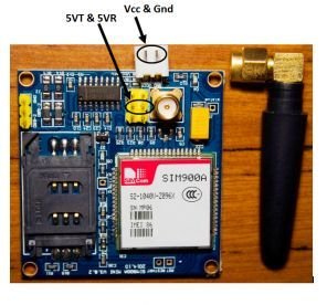
SIM900A Module Status Indicators
This GSM module has 2 LEDs to indicate its status, these are mentioned below
| Status LED | Function of LED |
|---|---|
| D5 | This LED remains on, but whenever a call arrives, it starts flashing. |
| D6 | This LED indicates the connection status of the GSM module. In case the GSM is not connected to any cellular network; this LED blinks every second. Once the GSM module connects to the cellular network, this LED starts blinking every 3 seconds, indicating a successful connection. |
How Does the SIM900A Module Work?
The SIM900 module is a GSM/GPRS modem that allows devices to communicate over cellular networks. It works by integrating the necessary hardware and software to establish a connection to the GSM network and facilitate data transmission. Here’s how the SIM900 module works:
Hardware Setup: The SIM900 module is a standalone unit that can be interfaced with microcontrollers or other devices using serial communication (UART). It typically requires a SIM card from a mobile network operator to access the network.
Network Registration: The first step in using the SIM900 module is to power it on and insert a valid SIM card. Upon powering on, the module initializes and searches for the GSM network to which it can connect. Once it finds a suitable network, it registers itself with the network, allowing it to operate as a valid mobile device on that network.
Sending AT Commands: To control the SIM900 module and communicate with it, you send AT commands to the module over the UART interface. AT commands are simple text commands that instruct the module to perform specific actions, such as making a call, sending an SMS, or connecting to the internet.
Voice and SMS Communication: Using AT commands, you can make voice calls and send SMS messages through the SIM900 module. When you send an SMS, the module communicates with the mobile network to deliver the message to the specified recipient.
GPRS Data Transmission: The SIM900 module also supports GPRS (General Packet Radio Service) for data communication. By configuring the module with the appropriate settings, you can establish a GPRS connection to the internet. This allows the module to send and receive data over the internet, enabling IoT applications, remote monitoring, and other data-driven tasks.
TCP/UDP Communication: With GPRS capabilities, the SIM900 module can establish TCP/IP or UDP connections to communicate with servers or other devices on the internet. This is particularly useful for applications that require real-time data exchange.
Low Power Modes: The SIM900 module is designed to be power-efficient. It can be put into sleep mode or power-down mode when not in use, reducing power consumption and extending battery life in battery-operated applications.
Overall, the SIM900 module acts as a bridge between your device and the GSM network, enabling voice, SMS, and data communication over cellular networks. Its versatility, compact size, and low power consumption make it a popular choice for various applications, such as remote monitoring, IoT projects, and communication in areas with limited wired internet access.
SIM900A Important AT Commands
Here are some important AT commands for the SIM900A GSM module:
| AT Command | Description |
|---|---|
| AT | Checks if the module is responding. |
| AT+CPIN? | Checks the status of the SIM card (PIN ready or not). |
| AT+CSQ | Checks the signal quality (measured in dBm). |
| AT+CREG? | Checks the registration status with the network. |
| AT+CGATT? | Checks if the device is attached to GPRS service. |
| AT+CIPSTATUS | Gets the connection status with the server. |
| AT+CIPSTART | Starts a TCP/UDP connection with the server. |
| AT+CIPSEND | Sends data to the server in TCP/UDP connection. |
| AT+CIPCLOSE | Closes the TCP/UDP connection with the server. |
| AT+CMGF=1 | Sets SMS text mode, allowing sending/receiving SMS in text format. |
| AT+CMGS=”number” | Initiates sending an SMS to the specified “number”. |
| AT+CMGR=index | Reads an SMS from the SMS memory with the specified “index”. |
Hardware Components:
Here we have listed the hardware components we will be using in this tutorial:
- Arduino UNO board
- SIM900A GSM Module
- Jumper Wires
- Cellular Network Card or SIM card
How to Test SIM900A GSM Module with SIM
In this section we have listed the steps to successfully boot our SIM900A GSM Module:
- Insert the SIM card into the GSM module and lock it.
- Connect the adapter to the GSM module and turn it ON!
- Now wait for some time (say 1 minute) and see the blinking rate of the status LED’ or ‘network LED’ (the GSM module will take some time to establish a connection with the mobile network).
- Once the connection is established successfully, the status/network LED will blink continuously every 3 seconds. You may try making a call to the mobile number of the SIM card inside the GSM module. If you hear a ring back, the GSM module has successfully established a network connection.
Okay! Now let’s see how to connect a GSM module to an Arduino board!
GSM Module with Arduino – Schematic Diagram
In this section, we have provided the schematic diagram. This schematic diagram helps us properly connect our Arduino Board to the SIM900A GSM module.
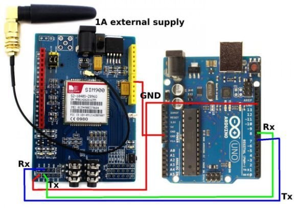
There are two ways of connecting SIM900A GSM Module to the Arduino board. These are explained below:
Arduino Communicating with GSM over Serial Connection
The first method includes serial communication between the SIM900A GSM module and the Arduino board. We can use the serial pins to connect the Arduino to the GSM Module. In this configuration, we will connect the Tx pin of the GSM Module to the Rx pin of the Arduino board. Similarly, we will connect the Rx pin of the GSM Module to the Tx pin of the Arduino Board. Now, we will connect the ground pin of the GSM module to the Ground pin of the Arduino board. With this, our schematic is complete using serial communication. We have also provided these connections in the table below:
| Pin of SIM900A GSM Module | Pin of Arduino Board |
| Tx | Rx |
| Rx | Tx |
| GND | GND |
Note: There is a problem with this method. Our Arduino board uses serial ports during programming to load the sketch from the Arduino IDE. In the event that these pins are connected to another module, the Arduino is unable to upload the code successfully. So we have to disconnect the module from the Tx and Rx pins of the Arduino board for successful uploading of our program to the board. Once the sketch is uploaded, we can again connect these pins, and they will not cause any problems.
Connecting with GSM using digital pins
For some users, this can be difficult while prototyping, where frequent changes in the program are required during calibration. We can use an alternate method to avoid this issue. This method requires an external library for serial communication with the SIM900A GSM Module using PWM-based digital pins. We will use two digital pins with PWM capability as serial pins for communication. The SoftwareSerial library replicates the hardware functions and handles the task of serial communication. We will be using Arduino pins 9 and 10 for serial communication. The connection table is provided below:
| Pin of SIM900A GSM Module | Pin of Arduino Board |
| Tx | 10 as Rx |
| Rx | 9 as Tx |
| GND | GND |
Arduino Sketch – SIM900A GSM Module
This code sets up communication between an Arduino and a GSM module (SIM900A) using SoftwareSerial. It allows the user to send an SMS or make a call by sending specific characters (‘s’ for SMS, ‘d’ for dialing) through the Arduino’s Serial Monitor. The GSM module is configured to send an SMS to a specified phone number with the message “I am SMS from GSM Module” when ‘s’ is received and to dial a specified phone number when ‘d’ is received.
Open the Arduino IDE and go to File > New to create a new file. Now copy this sketch given below and paste it in the Arduino File. Select the COM port of the connected Arduino board and click Upload. This will upload the sketch to the Arduino board.
#include <SoftwareSerial.h>

SoftwareSerial mySerial(9, 10);

void setup()
{
    mySerial.begin(9600); // Setting the baud rate of GSM Module
    Serial.begin(9600); // Setting the baud rate of Serial Monitor (Arduino)
    delay(100);
}

void loop()
{
    if (Serial.available() > 0)
    {
        switch (Serial.read())
        {
            case 's':
                SendMessage();
                break;
            case 'd':
                DialCall();
                break;
        }
    }
    if (mySerial.available() > 0)
    {
        Serial.write(mySerial.read());
    }
}

void SendMessage()
{
    mySerial.println("AT+CMGF=1"); // Sets the GSM Module in Text Mode
    delay(1000); // Delay of 1000 milliseconds or 1 second

    mySerial.println("AT+CMGS=\"+xxxxxxxxxxx\"\r"); // Replace x with mobile number
    delay(1000);

    mySerial.println("I am SMS from GSM Module"); // The SMS text you want to send
    delay(100);

    mySerial.println((char)26); // ASCII code of CTRL+Z
    delay(1000);
}

void DialCall()
{
    mySerial.println("ATD+xxxxxxxxxxxx;"); // ATDxxxxxxxxxx; -- watch out here for semicolon at the end!!
    delay(100);
}
Sketch Explanation
In this section, we are going to look at the above code and try to explain how each part works.
#include <SoftwareSerial.h>
SoftwareSerial mySerial(9, 10);
At first, we include the SoftwareSerial.h Library and assign pins 9 and 10 of the Arduino board for Serial communication using a mySerial constructor.
void setup()
{

  mySerial.begin(9600);   // Setting the baud rate of GSM Module
  Serial.begin(9600);    // Setting the baud rate of Serial Monitor (Arduino)
  delay(100);

}
In this section, we have initialized SoftwareSerial using the mySerial constructor and the Serial monitor at a baud rate of 9600. We have also added a delay of 100 ms.
void loop()
{

  if (Serial.available()>0)
   switch(Serial.read())
  {
    case 's':
      SendMessage();
      break;

    case 'd':
      DialCall();
      break;

  }

 if (mySerial.available()>0)

   Serial.write(mySerial.read());

}
In the void loop body, we check the Serial, and if communication is occurring, the value is greater than 0. Then we switch to the case using the Serial.begin function. Depending on the situation, the GSM module either sends a message or dials a number. At the last step, we print mySerial.read() using the Serial.write function of the serial monitor. If mySerial is available, the value is greater than 0, otherwise the value is less than 0.
void SendMessage()


{

  mySerial.println("AT+CMGF=1");    //Sets the GSM Module in Text Mode

  delay(1000);  // Delay of 1000 milli seconds or 1 second

  mySerial.println("AT+CMGS=\"+xxxxxxxxxxx\"\r"); // Replace x with mobile number

  delay(1000);

  mySerial.println("I am SMS from GSM Module");// The SMS text you want to send

  delay(100);

  mySerial.println((char)26);// ASCII code of CTRL+Z

  delay(1000);

}
This function is called based on the switch case. Using the AT command “AT+CMGF=1”, we set the SIM900A GSM Module in text mode. After a delay using another AT command “AT+CMGS=\”+phone-number\”\r”), we set the phone number to text using the GSM module. Next, we print the line for the text, and at the last section, we send the message using the CTRL + Z command based on ASCII characters.
 /*void RecieveMessage()

{

  mySerial.println("AT+CNMI=2,2,0,0,0"); // AT Command to recieve a live SMS

  delay(1000);

}

*/
This ReceivedMessage() function uses the AT command “AT+CNMI=2,2,0,0,0” with a delay of 1 s. At this time, if we send a message to the SIM card placed in the SIM900A GSM Module, it will display this message on the serial monitor of the Arduino IDE.
  void DialCall()

 {

  mySerial.println("ATD+xxxxxxxxxxxx;"); // ATDxxxxxxxxxx; -- watch out here for semicolon at the end!!

  delay(100);

 }
The switch statement calls the DialCall() function based on the Serial.read() case. In this function, we use the AT command “ATD+phone number;” to call this number using the SIM900A GSM Module.
Conclusion
Here we have provided a summary of topics we have covered in this tutorial:
- What is a GSM Module?
- SIM900A GSM Module and its features.
- Booting SIM900A GSM Module.
- Schematic diagram and connection methods.
- Sketch.
Related Article:
If you are interested in reading more similar articles, please check the link below:
- Introduction to SIM900A.
- Sending Data from GSM Module to a web server using Arduino.
- Home security system using PIR sensor and GSM module.
- Advanced Informative Blind Stick Using GPS and GSM Module.
- Receive SMS GSM Module using pic microcontroller.
- SIM300D GSM module.
- How to make call using gsm module on mobile phone.
- GSM Module interfacing with microcontroller.
is that possible to interface GSM module with micro controller ?
i need it to interface with micro controller my simulation to have multi purpose?
My English is small.But I learned your code.It’s good
I get “DialCall” was not declared in this scope , error message?
Hello sir.
Is it possible to send a variable value as text message??… for example, if i want to know the current of a system, then is it possible to send the value of current as text message??
Even I Have the same Doubt
the code was good.
sir, i’m beginner in arduino..i want ask a question..my question is .. what phone numbers should i enter in this code, if i want to run this code in Proteus ???
thank you very much as much as possible please connect to me arduino interface with motor and also sensor like moisture sensor for agricultural project
Sir why everytime i send sms the error is +CME ERROR 765 how to fix this sir
I need to know that if we are making call through GSM and the person who receive call then can that person listen the voice from GSM on live call? kindly suggest me for my project please.
Why my gsm is not blinking after I fix all the wirings part?
you should check your power supply. It have to have atleast 3 ampere rating.
sms received at gsm is too short 12 digits only
any solution to increase the size ??
Thanking you !!!
Hi,
May i use this combination to switch ON and OFF Borewell Motor remotely? can i get feedback once the borewell is turned On through a water flow switch or pressure switch ( Digital Input)? And How?
Yes you can by sending message string and take actions according to received message
D6 network light 💡on always why? What is the meaning of this?
Not sent massage/call….network light ON. The whole process not working please help..
This usually means, not network available. If the network is available. This light blinks with some delay.
When I am using GSM.h library and its methods instead of “AT” commands, a problem raised at the serial communication when we use SoftwareSerial.h . So , I used AltSoftSerial.h . I’m not getting error but I’m getting “%13%. I don’t know what it mean. Can some one please help me.
Thanks in advance.
all wiring is okey.and i supply the power from arduino instead of external source. both light of sgm module is on. the network light is blinking with out any delay ..and i cannt send sms from module.what should i do..please sir sugest any solution
Are the AT Commands being used in 4G Terminals?
Moi, j’ai un problème qui fait 5 jours , là commande AT ne revoit rien, j’ai déjà changer les cartes ARDUINO nano, mais hélas, je ne sais pas où est le problème, le module GSM est bien allumé et connecté sur le réseau mais la connexion être ce dernier et nano n’est pas établie, vraiment je suis bloqué depuis 5 jours de travail.