In this tutorial, we will focus on ESP8266 AT commands. The ESP8266 Wi-Fi module is basically a complete Wi-Fi solution, which has a self-contained integrated TCP/IP protocol stack that can be easily connected to the microcontroller for gaining access to any Wi-Fi network. AT is a mnemonic code for Attention. It is just like paying attention to anyone you want to communicate with. To know whether that person is ready to communicate with you or not, we want a response. Similarly ‘AT’ command is sent to Modem, as an attention command to communicate, and a very basic response is ‘OK’ from the modem.
ESP8266 Wi-Fi Module
In August 2014 Espressif Systems launched their first raw module which is manufactured by a third part AI-Thinker and module referred to as ESP-01 module.
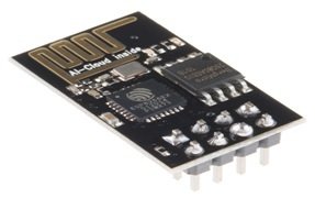
ESP8266 delivers a highly integrated WiFi solution that meets the needs of the Internet of Things industries such as low cost, efficient power usage, trustworthy performance, and compact design.
The ESP8266 Wi-Fi module is basically a complete Wi-Fi solution, which has self-contained integrated TCP/IP protocol stack that can be easily connected to the microcontroller for gaining access to any Wi-Fi network.
We will send AT commands to ESP8266 module over UART to configure the TCP Web server.
There are many ESP8266 Wi-Fi modules available in the market ranging from ESP-01 to ESP-12. But in this tutorial, we are using ESP-01. AT commands are the same for all these ESP modules.
ESP-01 Module pinout
The ESP8266-01 Wi-Fi module consists of two rows of eight pins. The pin configuration diagram is shown in the figure below:
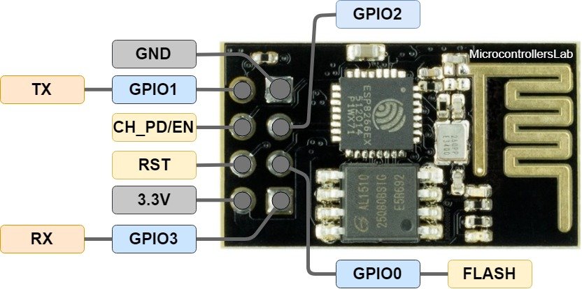
It has a total of 8 pins of which 6 pins are active.
| Label | Description |
|---|---|
| 3.3V | Supply 3.3 volts pin |
| GND | Ground pin |
| RST | Reset Pin |
| CH_PD/EN | Chip Power and Enable pin |
| GPIO 0 to 3 | UART interface and input/output pins |
- Pin_1, which is a GND pin, is directly connected to the ground for power on this module.
- Pins_2 and 3, which are the GPIO 2 and GPIO 0, these pins decide in which mode the module would be a start-up, in other words, these are mode selected pins.
- Pins_4 and 5, which are RX and TX, these pins are used for communication purposes and program the module.
- Pin_6 which is CH_PD, it is called chip power-down pin.
- Pin_7 which is the RST pin and this pin is used to reset module.
- Pin_8 is a VCC pin that is used to power the module. The operating voltage of ESP-01 is 3.3 volts.
Interface ESP8266 Wi-Fi Module with USB to TTL Converter
We will require the following components for this project:
- ESPP-01
- USB to TTL Converter
- Connecting Wires
- External 5V power supply (optional)
Unlike the ESP8266 NodeMCU, the ESP-01 does not come with the USB port attached to it. So we will need to use a USB to TTL Serial converter.
The table shows the connections between the ESP-01 and USB to TTL Converter:
| ESP-01 | USB to TTL Converter |
| 3.3V | VCC |
| RX | TX |
| TX | RX |
| GND | GND |
Connect the 3.3V pin of ESP-01 with the VCC pin of the USB to TTL converter to power up. Both grounds of the two devices will be connected in common. The TX pin of the converter will be connected with RX of ESP-01. Likewise, the RX pin will be connected with the TX of the ESP-01 module.
AT Commands Overview
After learning about the ESP8266 Wi-Fi module and interfacing it with the USB to TTL converter let us move ahead and learn about AT commands with this module.
Every AT command has three important parts which are prefix, a body, and a terminator.
- Prefix is known as ‘AT’.
- Body is the instruction/command to be executed(using ‘+’ or ‘&’ operator).
- Terminator is the carriage return<CR>.
The characters entered in the AT command must be in the same case, either upper or lower. The command is analyzed by the module after receiving the ENTER key character.
Response of AT commands
- AT commands response always start with <CR><LF>, and after this the response may be different according to the execution statement
- In case of incorrect syntax of the command, an ERROR is returned by the module.
- In case of correct syntax but with something inappropriate in parameters, INVALID INPUT PARAMETERS error is returned.
- If the command executed successfully, along with the reply that was required, an OK is also received.
Types of AT commands
AT commands can be handled in different ways. The types and the purpose of their difference in types are mentioned below:
- Test command: This command deals with a ‘?’, is known as the test command. This command tells about the value ranges of the parameters.
- Query command: This command also deals with a ‘?’, but this command tells us the values set by the user.
- Write command: This type of command consists of complete command to be executed. It actually sets the parameter values of the command.
- Execution command: This command is used very rarely and is used to execute an action. These commands are run without any parameters.
ESP8266 Wi-Fi Module Basic AT Commands
The ESP8266 has twenty three different basic AT commands. Let us discuss some commonly used ones.
AT: This type of command is used to test the startup function of Wi-Fi module. The response would be ok, against this command if everything is ok.
AT+RST: This type of command is used to reset the Wi-Fi module when it is in working condition. The response would be ok, when reset the module.
AT+GMR : This type of AT command is used to check the version of the firmware and SDK. The response would be ok and three other things including the AT firmware version, SDK version and the compilation time of the BIN file.
ATE0: This AT command turns OFF the echo mode of the module. The response is ok.
ATE1: ATE1 turns ON the echo of the module and AT0 turns it OFF. The response is ok.
AT+GSLP=<time>: This AT command sets the module into deep sleep mode where <time> specifies the number of milliseconds for which the device stays in deep sleep. The response is the <time> and ok, if everything goes fine.
AT+UART: This type of command is used to set the UART configuration and write the new configuration in flash. This means it is used for setting the default parameters.
AT+UART_CUR: This type of command is used to set the current UART configuration and does not write to the flash.
AT+UART_DEF: This type of command is used to set default UART configuration and save it in flash.
AT+UART_DEF?:
ESP8266 Wi-Fi Module Wi-Fi AT Commands
The ESP8266 has forty different Wi-Fi AT commands. Let us discuss some commonly used ones. Wi-Fi AT commands are used commonly when accessing Wi-Fi properties of the ESP-01 module. Some common features include setting up Wi-Fi mode, acquiring list of Wi-Fi networks. connecting to the Wi-Fi, setting up AP etc.
AT+CWMODE
This type of command is used to configure the Wi-Fi mode (Station/SoftAP/Station+SoftAP)
AT+CWMODE?: This type of command is used to query the Wi-Fi mode of ESP8266. The response is the <mode> and ok, if everything goes fine.
AT+CWMODE=<mode>: This is a set command that is used to set the Wi-Fi mode of ESP8266 according to the <mode> specified.
You can use the following values for <mode> :
0: Null mode. (Wi-Fi disabled)
1: Station mode.
2: SoftAP mode.
3: SoftAP + Station mode.
AT+CWMODE=?: This is a test command to obtain the value range of parameters. The response is the <mode> and ok, if everything is fine.
AT+CWJAP
This type of command is used to connect the module to an Access Point (AP).
AT+CWJAP?: This type of command is used to query the Wi-Fi mode of ESP8266. The response is <SSID>,<BSSID>,<channel>,<RSSI> and ok, if everything goes fine
AT+CWJAP=<SSID>,<PASSWORD>,[,<bssid>]: This connects the ESP8266 with an AP whose SSID and password are given.
The response is ok, if everything goes fine or <error> FAIL, incase of failure. Here <error> can take the following values:
1: Connection timeout.
2: Wrong password.
3: Cannot find the target AP.
4: Connection failed.
AT+CWLAP
This type of command is used to list all the available Access Point networks.
AT+CWLAP: This execute command will run without any parameters.
AT+CWLAP[=<ssid>,<mac>,<channel>,<scan_type>,<scan_time_min>,<scan_time_max>]: This set command sets the value of the parameters in the command and runs it. The specified parameters include SSID, MAC address, channel etc.
You can refer to the ESP8266 AT Commands Documentation to get to know the parameters and response values well.
AT+CWQAP
AT+CWQAP: This command is used to disconnect the module from an Access Point (AP). The response received is ok, if everything goes fine.
AT+CIPSTA
This command is used to write or query the IP address of the module.
AT+CIPSTA?: This type of command is used to query the IP address, gateway and netmask of the module. The response is +CIPSTA:<ip> +CIPSTA:<gateway> +CIPSTA:<netmask> and ok, if everything goes fine.
AT+CIPSTA=<ip>[,<gateway>,<netmask>]: This command sets the IP address, gateway and netmask of the module. The response is ok , if everything goes fine.
AT+CWSAP
This command is used to query and set the configuration of the ESP8266 Wi-Fi module in SoftAP.
AT+CWSAP?: This query command is used to query the configuration of the ESP8266 Wi-Fi module in SoftAP. The response is +CWSAP:<ssid>,<pwd>,<chl>,<ecn>,<max conn>,<ssid hidden>
AT+CWSAP =<ssid>,<pwd>,<chl>,<ecn>[,<max conn>][,<ssid hidden>]: This command sets the configuration of the ESP8266 Wi-Fi module in SoftAP on the given parameters. The response is OK in case of success and ERROR, in case of failure.
AT+CWLIF
AT+CWLIF: This execution command is used to obtain the IP address of the station that is connected to the ESP8266 Wi-Fi module’s SoftAP. The response is <ip addr>,<mac> and OK in case of success. Here <ip addr> denotes the IP address of the station and <mac> denotes the MAC address of the station.
ESP8266 Wi-Fi Module TCP/IP AT Commands
The ESP8266 has twenty five different TCP/IP AT commands. Let us discuss some commonly used ones. TCP/IP AT commands are used when communicating over the internet.
AT+CIPSTATUS
AT+CIPSTATUS: This is an execution type command that is used to acquire the TCP/UDP/SSL connection status and its information. The response is
STATUS:<stat>
+CIPSTATUS:<linkID>,<type>,<remoteIP>,<remoteport>,<localport>,<tetype>
Here the <linkID> is the ID of the connection, <type> is either “TCP” or “UDP”, <remoteIP> is the remote IP address, <remoteport> is the remote port number and <localport> is the local port number.
Here <stat> can take the following values:
0: ESP8266 module is not initialized.
1: ESP8266 module is initialized, but a Wi-Fi connection is not started.
2: ESP8266 is connected to an AP and its IP is obtained.
3: Created a TCP or UDP transmission.
4: TCP/UDP/SSL connections are disconnected.
5: ESP8266 is not connected to AP but a Wi-Fi connection is initiated.
and <tetype> can take the following values:
0: ESP8266 as a client.
1: ESP8266 as a server.
AT+CIPSTART
This set command is used to establish TCP/SSL Connection or UDP Transmission.
- For single TCP connection:
AT+CIPSTART=<type>,<remoteIP>,<remoteport>[,<TCPkeepalive>]
- For multiple TCP connection:
AT+CIPSTART=<linkID>,<type>,<remoteIP>,<remoteport>[,<TCPkeepalive>]
Here <link ID> is the ID of connection, <type> is “TCP”, “UDP” or “SSL”, <remoteIP> is the remote IP address, <remoteport> is the remote port number and [<TCPkeepalive>] is the detection time interval.
The response is OK in case of success and ERROR in case of failure.
AT+CIFSR
AT+CIFSR: This execution command obtains the local IP address and the MAC address of the ESP8266 Wi-Fi module.
The response is as follows:
+CIFSR:APIP,<SoftAPIPaddress>
+CIFSR:APMAC,<SoftAPMACaddress>
+CIFSR:STAIP,<StationIPaddress>
+CIFSR:STAMAC,<StationMACaddress> and OK if everything goes well.
Here the <SoftAPIPaddress> is the IP address of the ESP8266 SoftAP, <SoftAPMACaddress> is the MAC address of the ESP8266 SoftAP, <StationIPaddress> is the IP address of the ESP8266 Station and <StationMACaddress> is the MAC address of the ESP8266 Station.
AT+CIPMUX
This command is used to enable/disable multiple connections. It is available as query and set command.
AT+CIPMUX?: This command will query the type of connection. The response is +CIPMUX: <mode> and OK, if everything goes well. Here <mode> can take the following values:
0: single connection.
1: multiple connections.
AT+CIPMUX=<mode>: This command will set the connection type according to the <mode> specified. The response is OK, if everything is fine.
AT+CIPSERVER
This command is used to create/delete a TCP/SSL server. It is available as query and set command.
AT+CIPSERVER?: This command is used to query the status of the TCP/SSL server. The response is +CIPSERVER:<mode>[,<port>,<“type”>][,<CA enable>] and OK, incase of success.
AT+CIPSERVER=<mode>[,<port>]: This set command is used to create/delete a TCP/SSL server according to the set parameters. Here the <mode> can take the following values:
0: Delete Server.
1: Create Server.
The response if OK if everything goes fine.
Points to Note:
- A TCP/SSL server can only be created when multiple connections are enabled. This is when AT+CIPMUX=1.
- At maximum, only one server can be created.
- A client connected to the server, takes up one connection and be allotted an ID.
aoa really helpfull kindly upload the coad for convinence
further interfancing picture is not clear kindly explain it little bit more
in short Thank you
Hi Bilal
please answer me if it is possible to use ESP8266 Wifi Module to do the same job as normal RF circuit TX abd RX
when data is send and received ESP 8266 executed same way as the RF circuit TX and RX do
Thanks
Varoosh Shamavonian
I want working principle of esp8266-01 wifi module ..
hii I want to interface four p6 led module to node MCU to send data using wifi and i have tried to Connect but the data was not displaying properly, and i used serial data and also used dmd library but i don’t receive any data to p6led module ( indore )