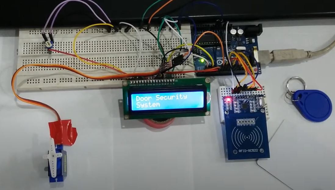
This Arduino based project focuses on creating a door security system using RFID RC522. Firstly, we will interface RC522 RFID module with Arduino and then use it to design a door security system.
A door Security System is used to stop unauthorized people to get access to a room or a building. Such system is very useful if you have important data, information, and research stored in a computer or in a bundle of files. This system is very useful in the Military, Research Centers, Banks, Server rooms, Jails, Government offices, and Nuclear Plants. It prevents large destruction and loss.
Recommended Components
The following components are used in this project or are helpful for building it with the Arduino.
| Component | How it’s used in this project | Buy on Amazon |
|---|---|---|
| Arduino Uno R3 | The main controller board that runs the project sketch and coordinates all the connected modules. | Check Price |
| RC522 RFID Reader | Reads the RFID card/tag UID so the Arduino can check it against the authorised tokens. | Check Price |
| Servo Motor (SG90) | Acts as the lock, rotating to open and close the door when access is granted. | Check Price |
| Buzzer Module | Sounds an alert when an unauthorised card is presented. | Check Price |
| Breadboard | Lets you prototype and wire the circuit without soldering. | Check Price |
| Jumper Wires | Used to make the connections between the Arduino, modules and breadboard. | Check Price |
As an Amazon Associate we earn from qualifying purchases. Prices and availability are accurate as of the date/time indicated and are subject to change.
RFID Door Security System Overview
We will require the following components for this project.
Required Components:
- Arduino Uno: We will use Arduino due to its easy use. It also provides several digital pins to interface with the servo motor and RFID module at the same time. It is very friendly when you prototyping any project.
- RFID RC522: This module is based on MFRC522 IC which is used in contactless communication. It is used both as a reader and a writer.
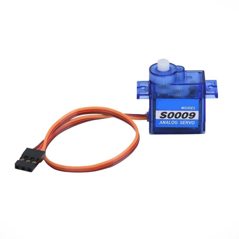
- SG-90 Servo Motor: SG90 is a low-cost and high output power servo motor. In this project, servo motor is used to indicate that the door is opening and closing. It is easy to use and program and also provides precise movement. Learn more about servo at servo motor interfacing with Arduino
- 16×2 LCD: 16×2 LCD is used to display 16 text/characters in two lines. It has a total of 16 pins. A 10K ohm potentiometer is connected with pin three to set the contrast of the LCD. It also contains a backlight LED. In this project, LCD is used to show messages.
- Jumper wires
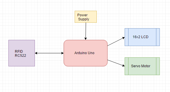
Door Security System Block Diagram
In this RFID door security system, Arduino Uno is used as the brain of our circuit.
You can view the operations constituting the system in the block diagram below:
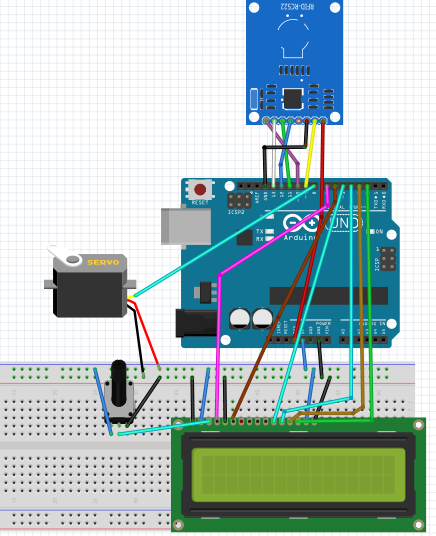
Connection Diagram of RFID Door Security System
This section will explain the connections of the various components specified above with Arduino Uno to form the door security system.
Let us discuss them one by one.
Arduino with RC522
RC522 is a Multi-communication RFID Module for Arduino and Microcontrollers. The RC522 is known as MFRC-522 due to its NFX semiconductor microcontroller. The module allows the developers to interface it with any other SPI, I2C, and UART based microcontrollers. It comes with an RFID card tag and key fob consisting of 1KB of memory.
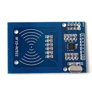
The RC522 module works on 13.56 MHz frequency and it can act as a reader and write for UID/RFID cards. The RFID cards communicate with the module at a short distance with radio frequency due to the mutual induction technique. In most of the security and commercial products, the module is effective because the errors and issues with RFID Tags are detectable by it.
In this module, there are only two kinds of pins. So, the first one is power and the second one is the communication pins. Therefore, the device may have its microcontroller chip on itself but it only makes it to works as an RFID. The onboard microcontroller won’t make the module a stand-alone device.
RC522 Pinout
All the pins of MFRC/RC522 RFID card Reader are:
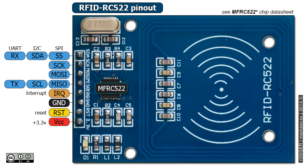
The table below shows the eight pins found on the RC522 RFID module. You can also view their descriptions.
| Pin | Description |
|---|---|
| VCC | The power pins are VCC. In some versions of RC522, this pin is denoted by 3V3 on the module instead of VCC. |
| RST | This is the reset pin for the module. Therefore, it resets the device in case of an error when a device isn’t giving any response. |
| GND | Ground helps to make the common ground with every external device, e.g. power Supply or microcontroller. |
| IRQ | The device can go into sleep mode to save power. So, the IRQ helps to wake it. |
| MISO | This pin connects with the microcontroller for SPI communication. However, it transfers the data from module to the microcontroller. The MISO pin is also useable for other functions instead of SPI. It can also interface with I2C for clock pulse and UART Serial for Data transfer from the module. |
| MOSI | MOSI is the data input pin for RFID module in SPI communication |
| SCK | The SCK pins help to send the clock pulse in SPI communications. |
| SS | The SS pin is a chip enable pin in SPI communication. Therefore, it receives the signal when Master (Arduino) must perform SPI communication. The SS pin in RFID is useable as a second pin (SDA) for I2C communication. It also receives data during UART communication. |
For more information follow the link below:
The table below shows the connections between the devices that we will use in our project.
Connections of RC522 Module with Arduino
| RC522 RFID Reader Module | Arduino |
|---|---|
| VCC | 3.3V |
| RST | Pin 9 |
| GND | GND |
| IRQ | Not connected |
| MISO | Pin 12 |
| MOSI | Pin 11 |
| SCK | Pin 13 |
| SDA | Pin 10 |
Arduino with 16×2 LCD
We will use a 16×2 LCD in our project to display different messages. To connect a 16×2 LCD with Arduino we will require an additional 10k potentiometer as well.
We have a dedicated tutorial regarding interfacing 16×2 LCD display with Arduino with some example sketches. Have a look at it before proceeding further for a better understanding of the LCD.
Recommended Reading: 16×2 LCD Interfacing with Arduino – Explained with Example Codes
There are two types of pins on the whole 16×2 LCD module. Some pins are used to send to 16×2 LCD and some are command pins. In other words, every pin has a role in controlling a single pixel on the display.16 x 2 LCD has sixteen columns and two rows. That means, it can display sixteen characters per row and it has two such rows.
Pinout
The diagram shows the pin configuration of a 16×2 LCD display. It has sixteen pins.

- D0 – D7: Pin number 7-14 are data bus lines that are used to send data from Arduino which you want to display on LCD. With these 8 data lines, data can be transferred either in an 8-bit format or in a 4-bit format. In a 4-bit format, only upper four bits (D4-D7) are used to send data from Arduino to LCD. The full byte is transmitted in two successive transmissions. A 4-bit format is used to save GPIO pins of Arduino. Because fewer GPIO pins of Arduino will be required to transfer data.
- Contrast Select (VEE): It will help to control the contrast of PIXELS according to the 16X2 LCD light.
- RS: This pin is known as a register select pin. It helps to toggle the command/data register.
- R/W: The signal on this pin will decide whether it is going to read from LCD or write on it.
- EN: Enable pin will help to transfer the instruction from the data pins and another command pin to the LCD. It act as permission to internal registers.
- VSS: It’s a ground pin for common grounds.
- VCC: The power pin will use for voltage input to the 16X2 LCD.
Arduino connections with 16×2 LCD
We are using the following connections as described below. Refer to the schematic diagram to have a clearer idea of the connections.
| 16×2 LCD | Arduino |
|---|---|
| D4 – D7 | Pin 5,4,3,2 |
| Enable | Pin 6 |
| RS | Pin 7 |
| RW | GND |
| VEE | 10k POT (Middle Leg) |
| VSS | GND |
| VCC | +5V |
| LED+ | +5V |
| LED- | GND |
We have an Arduino library for easy communication between LCDs called the LiquidCrystal library. It is an inbuilt library by Arduino Adafruit version.
You may also like to read:
Arduino with Servo Motor
SG90 is a low-cost and high output power servo motor. It can rotate up to 180 degrees and each step can be of maximum of 90 degrees. Moreover, it is small enough that it can easily fit into your robotics ARM or obstacle avoidance robotics projects. On top of that, it requires only one output pulse signal to control its movement.
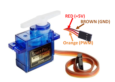
The following figure shows the pinout diagram of SG90 servo motor. It consists of three pins only such as PWM, ground and Vcc pin. Brown, orange and red wires are GND, Vcc and PWM pins respectively. Details and functionality of each pin is listed in the next section.
Pin Configuration Details
Vcc and ground, as their name suggests, are the power supply pins which are used to a power servo motor. Only 5 volts of power signal is required to power this motor. Mostly microcontrollers or development boards have onboard 5 volts supply which we can use to power SG90 servos.
This table briefly describes all three pins:
| Wire of motor | Possible colors of each wire |
|---|---|
| VCC pin | Red |
| GND pin | Black, or brown |
| Control Signal / PWM pin | Yellow, orange, or white |
Connections of Servo motor with Arduino are as follows:
| Servo Motor | Arduino |
|---|---|
| VCC pin | 5V |
| GND pin | GND |
| Control Signal | Pin 8 |
Door Security System Using RFID RC522
When the user brings the token near the module it detects the token and reads its value. If the value is same as defined in the code then Access Granted message is shown on LCD and it opens the door for the user. After some delay which is also defined in the code the door automatically closes. This process occurs every time the user wants to access it. There can be multiple users but each user has it unique token.
Arduino Code
Open your Arduino IDE and go to File > New to open a new file. Copy the code given below in that file and save it.
#include <deprecated.h>
#include <MFRC522.h>
#include <MFRC522Debug.h>
#include <MFRC522Extended.h>
#include <MFRC522Hack.h>
#include <require_cpp11.h>
#include<RFID.h>
#include <SPI.h>
#include <Servo.h>
#include <LiquidCrystal.h>

LiquidCrystal lcd(7, 6, 5, 4, 3, 2);

Servo myservo; // create servo object to control a servo

#define val0 117 // chnage the value according to token no
#define val1 134
int pos = 0;
/* Define the DIO used for the SDA (SS) and RST (reset) pins. */
#define SDA_DIO 10
#define RESET_DIO 9
RFID RC522(SDA_DIO, RESET_DIO);

void setup()
{
  myservo.attach(8);
  Serial.begin(9600);
  /* Enable the SPI interface */
  SPI.begin();
  /* Initialise the RFID reader */
  RC522.init();
  lcd.begin(16, 2);

}

void loop()
{
  byte i = 0;
  int ID;
  if (RC522.isCard())
  {
    RC522.readCardSerial();
    Serial.println(RC522.serNum[i], DEC);
    Serial.println("Card detected:");
    ID = RC522.serNum[0];
  }
  delay(500);
  if ( val0 == ID)
  { lcd.clear();
    lcd.print("Access Granted");
    lcd.setCursor(0, 1);
    lcd.print("Welcome Haris");
    delay(1800);
    lcd.clear();
    lcd.print("Door Opening");
    delay(1500);
    for (pos = 0; pos <= 180; pos += 1) { // goes from 0 degrees to 180 degrees
      // in steps of 1 degree
      myservo.write(pos); // tell servo to go to position in variable 'pos'
      delay(15); // waits 15ms for the servo to reach the position
    }
    delay(5000);
    lcd.clear();
    lcd.print("Door Closing");
    delay(1500);
    for (pos = 180; pos >= 0; pos -= 1) { // goes from 180 degrees to 0 degrees
      myservo.write(pos); // tell servo to go to position in variable 'pos'
      delay(15); // waits 15ms for the servo to reach the position
    }
  }
  else
  {
    lcd.clear();
    lcd.print("Door Security ");
    lcd.setCursor(0, 1);
    lcd.print("System ");
  }
  if ( val1 == ID)
  { lcd.clear();
    lcd.print("Access Granted");
    lcd.setCursor(0, 1);
    lcd.print("Welcome Bilal");
    delay(1800);
    lcd.clear();
    lcd.print("Door Opening");
    delay(1500);
    for (pos = 0; pos <= 180; pos += 1) { // goes from 0 degrees to 180 degrees
      // in steps of 1 degree
      myservo.write(pos); // tell servo to go to position in variable 'pos'
      delay(15); // waits 15ms for the servo to reach the position
    }
    delay(5000);
    lcd.clear();
    lcd.print("Door Closing");
    delay(1500);
    for (pos = 180; pos >= 0; pos -= 1) { // goes from 180 degrees to 0 degrees
      myservo.write(pos); // tell servo to go to position in variable 'pos'
      delay(15); // waits 15ms for the servo to reach the position
    }
  }
  else
  {
    lcd.clear();
    lcd.print("Door Security ");
    lcd.setCursor(0, 1);
    lcd.print("System ");
  }
}
How the Code Works?
First include all the necessary libraries required for this project. These include libraries for the RC522 module, servo motor and the LCD.
#include <deprecated.h>
#include <MFRC522.h>
#include <MFRC522Debug.h>
#include <MFRC522Extended.h>
#include <MFRC522Hack.h>
#include <require_cpp11.h>
#include<RFID.h>
#include <SPI.h>
#include <Servo.h>
#include <LiquidCrystal.h>
Next, we declare the Arduino pins that are connected with the LCD. To define connections, we use the following line of code. This line creates a LiquidCrystal object and lcd is a name of the object that we are going to use to call LCD functions. You can also use any other name.
LiquidCrystal lcd(rs, en, d4, d5, d6, d7)In our case, the pins are 7, 6, 5, 4, 3, and 2 respectively.
LiquidCrystal lcd(7, 6, 5, 4, 3, 2);Then we will create an object of the Servo library called ‘myservo.’ You can use any other name as you like.
Servo myservo;Specify the token numbers:
#define val0 117 // change the value according to token no
#define val1 134
Define the Arduino pins connected with SDA and RST of the RC522 module. Then create an instance of the RFID library.
#define SDA_DIO 10
#define RESET_DIO 9
RFID RC522(SDA_DIO, RESET_DIO);
setup()
Inside the setup() function, we will first open the serial communication at a baud rate of 9600.
Serial.begin(9600);Then attach the Arduino pin connected with the signal pin of the servo with the servo object.
myservo.attach(8);Also, enable the SPI interface using SPI.begin().
SPI.begin();Also, initialize the RC522 module using the init() method on the RFID instance.
RC522.init();Next, we use lcd.begin() routine to define the size of an LCD. The first argument to this function is a number of rows and the second argument is a number of columns. For instance, this line declares the size as 16 columns and 2 rows. That means 16×2 size.
lcd.begin(16, 2);
loop()
Inside the loop() function, we first check if an RFID card is detected. If it is then save its serial number in the variable ‘ID.’
  byte i = 0;
  int ID;
  if (RC522.isCard())
  {
    RC522.readCardSerial();
    Serial.println(RC522.serNum[i], DEC);
    Serial.println("Card detected:");
    ID = RC522.serNum[0];
  }
Then we will check if this ID matches the token numbers we already specified in the code previously. We specified tokens for two different cards hence two cards/users will be granted access. The LCD will display “Access Granted”, a welcome message and the door opening message.
We will move the servo motor’s arm clockwise to show door opening and anti-clockwise to show door closing. This is done using the write() method on the servo object. We are passing the ‘pos’ variable as a parameter inside this function. This will position the servo arm according to the values held in the ‘pos’ variable that will first vary from 0-180 degrees and then 180 to 0 degrees by using a for loop. When the servo arm moves anticlockwise, the LCD will display “Door Closing”
  if ( val0 == ID)
  { lcd.clear();
    lcd.print("Access Granted");
    lcd.setCursor(0, 1);
    lcd.print("Welcome Haris");
    delay(1800);
    lcd.clear();
    lcd.print("Door Opening");
    delay(1500);
    for (pos = 0; pos <= 180; pos += 1) { // goes from 0 degrees to 180 degrees
      // in steps of 1 degree
      myservo.write(pos); // tell servo to go to position in variable 'pos'
      delay(15); // waits 15ms for the servo to reach the position
    }
    delay(5000);
    lcd.clear();
    lcd.print("Door Closing");
    delay(1500);
    for (pos = 180; pos >= 0; pos -= 1) { // goes from 180 degrees to 0 degrees
      myservo.write(pos); // tell servo to go to position in variable 'pos'
      delay(15); // waits 15ms for the servo to reach the position
    }
  }
  else
  {
    lcd.clear();
    lcd.print("Door Security ");
    lcd.setCursor(0, 1);
    lcd.print("System ");
  }
  if ( val1 == ID)
  { lcd.clear();
    lcd.print("Access Granted");
    lcd.setCursor(0, 1);
    lcd.print("Welcome Bilal");
    delay(1800);
    lcd.clear();
    lcd.print("Door Opening");
    delay(1500);
    for (pos = 0; pos <= 180; pos += 1) { // goes from 0 degrees to 180 degrees
      // in steps of 1 degree
      myservo.write(pos); // tell servo to go to position in variable 'pos'
      delay(15); // waits 15ms for the servo to reach the position
    }
    delay(5000);
    lcd.clear();
    lcd.print("Door Closing");
    delay(1500);
    for (pos = 180; pos >= 0; pos -= 1) { // goes from 180 degrees to 0 degrees
      myservo.write(pos); // tell servo to go to position in variable 'pos'
      delay(15); // waits 15ms for the servo to reach the position
    }
  }
  else
  {
    lcd.clear();
    lcd.print("Door Security ");
    lcd.setCursor(0, 1);
    lcd.print("System ");
  }
}
Demonstration
Make sure you choose the correct board and COM port before uploading your code to the board. Go to Tools > Board and select Arduino UNO. Next, go to Tools > Port and select the appropriate port through which your board is connected.

Click on the upload button to upload the code to the board.
Bring the RFID tag or card close to the RC522 module. If access is granted, the LCD will display relevant messages and the servo motor will start moving to indicate that the door is opening. After few seconds, the servo motor goes back to its initial position indicating the door is closing.
Watch the video demonstration below for better insight:
You may also like to read:
- MAX30102 Pulse Oximeter and Heart Rate Sensor with Arduino
- MAX30100 Pulse Oximeter and Heart Rate Sensor with Arduino
- Control Stepper Motor with A4988 Driver Module and Arduino
- Interface nRF24L01+ Wireless Module with Arduino
- TM1637 4 Digit 7 Segment Display Module with Arduino
- RDM6300 RDM630 RFID Reader interfacing with Arduino
Where can I download the code ?
HI
where i download the code
where i download the code
hi
me arroja esto?
RC522.init();
‘class RFID’ has no member named ‘init’
no es las bibliotecas de arduino?