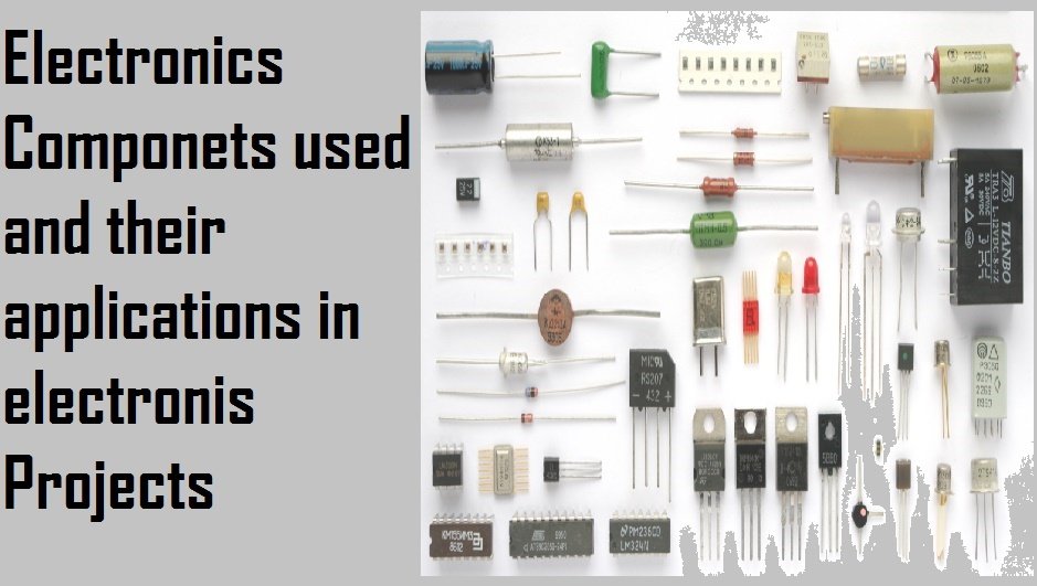
In this comprehensive article, we will delve into the fascinating world of electronics components, exploring their various types and applications in electronics projects. By the end of this read, you will gain a thorough understanding of the fundamental electronic components and how they are utilized in various electronic projects. Additionally, we will provide an informative visual aid by including circuit symbols for each component discussed. So, without further ado, let’s dive into the list of essential electronics components and explore their wide range of applications:
List of electronic components
- Resistor
- capacitors
- diodes
- Light emitting diodes
- switches
- Transistors
- Wire connections
- power supplies
- fuse
- transformer
- Microphone
- Earphone
- Loudspeaker
- piezo transducers
- amplifier
- Antenna
- volt meter
- Ammeter
- galvanometer
- ohm meter
- oscilloscope
- lamp
- heater
- motor
- bell
- inductor
List of electronic components I have explained in this article is given above. I have also explained the types of these electronic components. Let’s start with the resistor.
Resistor :
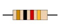

Resistors oppose the current flow in a circuit. For example, a resistor is placed in series with a light emitting diode to limit the current flowing through it. Resistors can be connected in series or parallel configurations without any risk of damage, as they only get damaged by excessive heat. Resistance is measured in ohms (Ω). The resistance values start from 1Ω and can go up to megaohms. These values are represented using a color code system, where each color band on the resistor symbol corresponds to a specific number. By following a procedure, you can calculate the value of a resistor using the color code system.

- First color band represents the first digit
- The second color band represents the second digit
- Third color band represents the number of zeros
- Fourth color band provides the tolerance of the resistor which may be ±5 %.
By following the above-given four steps, one can easily calculate the value of a resistor without using any measurement meter. Ohm meters are also available, which can be used to measure the resistance of a resistor.
Types of resistors
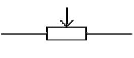
Rheostat: It is a type of variable resistor with two contacts. It is used to limit current in a circuit. For example, a rheostat is used to control lamp brightness, and the speed control of a DC motor, and it is also used in timing circuits to control the flow of charges to a capacitor. The circuit symbol of a rheostat is given below.

Potentiometer: It is a variable resistor with three contacts. It is used to control voltage. It is used in many applications where we need to convert current into voltage form. A potentiometer is used as a transducer to convert one physical force into voltage form, such as an angle of control spindle. The circuit symbol of a potentiometer is given below:
Preset variable resistor :
It is another type of variable resistor. As its name suggests, it is a preset variable resistor. It is designed to be set when the circuit is made. It is adjusted with the help of a screwdriver. The cost of a preset resistor is less than other types of variable resistors. Therefore, it is mostly used in electronics projects to make them more economical. The circuit symbol of a preset resistor is given below:

Capacitors :
Capacitors are used to store electrical charge through an electric field. Capacitors store charge between two plates of the capacitor. I am not going to discuss the working and internal construction of the capacitor because it needs an extra article to discuss it completely. Capacitors are also used in timing circuits along with resistors. There are enormous applications of capacitors in the electrical field. For example, capacitors are used in filter circuits due to their feature to pass AC signals and block DC signals. Generally, capacitors are of two types: polar capacitors and non-polar capacitors.
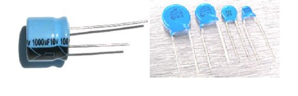
Capacitance is measured in farads and denoted by F. One farad (1F) is a very large value of capacitance. Therefore, capacitance is represented using small prefixes. Usually, three prefixes are used to denote the value of capacitors: micro (μ), nano (n), and pico (p).
Types of capacitors :
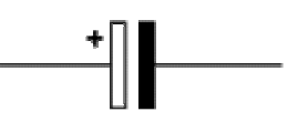
Polar capacitor :
Polarized capacitors are usually used in DC circuits. They are used to store electrical energy. This type of capacitor has polarity, which means it should be connected properly with respect to positive and negative terminals. It is used in timing circuits and filter circuits to block DC and pass AC. The circuit symbol of a polar capacitor is given below:
Non polar capacitor :
Non-polarized capacitors are used in AC circuits. They are used to remove harmonics from AC signals and allow only specific frequency signals to pass into the circuit. The circuit symbol of a non-polar capacitor is given below:

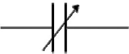
variable capacitor :
Variable capacitor, as its name suggests, is used to obtain variable capacitance. It is used in a radio tuner circuit to change the frequency of a channel. In radio, when you move the knob, you are actually changing the capacitance. The change in capacitance alters the frequency modulation of the circuit, allowing you to tune in to the desired channel. The circuit symbol of a variable polar capacitor is shown below:
trimmer capacitor :
Just like a preset resistor, a trimmer capacitor is operated with a small screwdriver. It is also set during circuit design. Its value is adjusted before using it in a circuit. The circuit symbol of a trimmer polar capacitor is given below:

Diodes :
Diodes are electronic devices that allow current to flow only in one direction. A practical diode and the circuit symbol of a diode are shown below. The arrow in the circuit symbol indicates the direction of current flow, with the arrow pointing towards the cathode and away from the anode. The diagram also includes the circuit symbol for a zener diode, which I will explain later. Diodes have many applications in electrical and electronic circuits. For example, rectifier diodes are used to convert AC signals into DC during rectification. Zener diodes are used in voltage regulator circuits. Diodes are also used as free-wheeling diodes. Similarly,

Type of diodes :
zener diode :
Zener diode is a special-purpose semiconductor diode. It is used to maintain a fixed voltage in regulated power supplies.

Light emitting diode :
A light-emitting diode (LED) is a type of transducer that converts electrical energy into light energy.

photodiode :
It is a special type of diode that converts light energy into electrical energy. The same process is used in solar cells.

Switches:
Push switch:
This is a simple push button that permits current flow only in one direction when the button is pressed. It has many applications, such as electronic circuits, doorbells, LED lights, charging lights, and many others. The circuit of the push switch is shown below:

Push to break switch:
It also allows current to flow only in one direction. But it works opposite to a push switch. It stops current from flowing when the button is pressed. It is used in applications where we want continuous power to the circuit until the button is not pressed. The circuit symbol of the push-to-break switch is shown below:

Single pole single through switch (SPST):
It also allows current to flow in one direction, but it has two states: the on state and the off state. SPST switches are used in domestic and industrial switchboards. The symbol of an SPST switch is shown below:

Single pole double through switch (SPDT):
As its name suggests, a single pole double throw switch connects with one phase and allows the current to flow in one of two possible circuits or routes. As shown in the figure, either the upper or lower route can be connected to the single-phase supply.

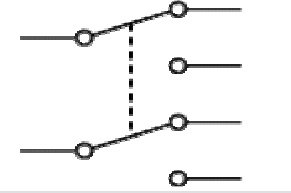
Double pole single through switch (DPST):
It allows current to flow only in one possible route according to the respective pole. It can be used to switch the main electric supply. It can be used to isolate the neutral and live connections of the main power supply. The circuit symbol of a DPST switch is shown below:

Double pole double through switch:
It is also called a reversing switch. It can be used to reverse the direction of a motor. It also has a central off position. The DPDT circuit symbol is shown below:
Relay:
It is an electromechanical switch that operates with an external power source. It is used to operate high power or high voltage circuits with low power DC circuits. It can be either normally closed or normally open. All three of its terminals are shown below:

TRANSISTORS
Three types of transistors are used in electronics projects. A description of each of them is given below:
NPN transistor:
NPN transistor used in many electronics circuits. It is used as a switch, amplifier and current amplifier and also in oscillator circuits. Circuit symbol of NPN transistor is shown below:

PNP transistor:
PNP transistor has same applications like NPN transistor. But the direction of current flow is opposite in PNP transistor. PNP and NPN transistor together also used to make Darlington pair and totem pole configuration.
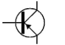
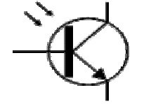
Photo transistor:
It is light operating transistor. Photo transistor operates with intensity of light. Whenever amount of light fall on base of transistor, it turns on. Photo transistor has many applications in automatic street light control circuit and auto intensity control of street lights.
Wiring and electrical connections in electronics circuits:
It is important to understand wiring connection to understand electrical diagrams. Following symbols are mainly used for wiring connections in electrical circuits.
Wire:
It is just a line which is used to represent path of current. It is shown below:

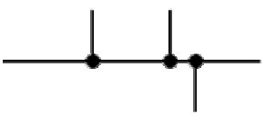
Joint:
As shown in figure below, sold bold circle is used to represent one of more connection of wires. In other words, a point where two or more wires connect with each other.
Not connected point or wires crossing:
In electrical electronics circuit wires crossing symbol shows not connected point. Wires crossing symbol is shown below:

Power supplies:
Following types of powers supplies are used in electronics and electrical projects.
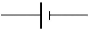
Cell:
Circuit symbol of cell is shown below. Larger terminal shows positive terminal of cell and smaller terminal shows negative terminal of cell. Many people used to call battery to cell. But in electrical battery consists of two or more cells.
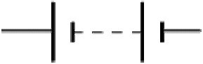
Battery:
Electrical symbol of battery is shown below. As I have mentioned earlier, battery consists of two or more cells. Battery supplies DC electrical energy.
DC supply:
DC power supply supplies dc current which flows in one direction only. DC power supply can be made from AC power supply or using batteries. Circuit symbol of DC power supply is shown below:

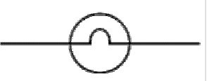
AC supply:
AC power supply alternating current. Circuit symbol of AC power supply is shown below:

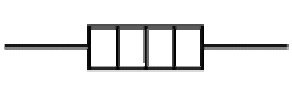
Fuse:
Fuse is very important components of electrical circuits. It provides protection to circuit in case of over current or short circuit in electronics circuits. Fuse melts when excessive current flows through circuit.

Transformer:
Transformer is mainly used in AC circuits. But it is also used in dc power supplies to step down voltage. Transformer can be used either as step down or step up transformer. Transformer used electromagnetic induction to transfer energy from one circuit to another. Circuit symbol of transformer is shown below:

Audio and Radio devices:
Microphone:
It is a transducer which converts sounds into electrical energy. Its circuit symbol is shown below:

Earphone:
It is a transducer which converts electrical energy into sound. Circuit symbol is shown below:

Loud Speaker:
It is also used to convert electrical energy into sound with high amplification ability.

Piezo transducer:
Piezo transducer converts force (stress) into electrical energy.

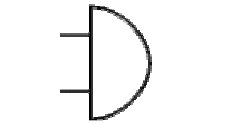
Amplifier:
Amplifier has many applications in electrical and electronics projects. Amplifiers are used to amplify voltage, current and signals level. Circuit symbol of amplifier is shown below.

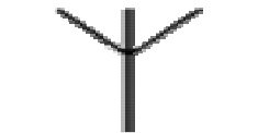
Antenna:
Antenna is a device which is used to transmit and receive data through wireless communication. Antenna is used to receive and transmit radio waves. Circuit symbol of antenna is shown below.
Output devices:
Followings are the list of electronics output devices used in electronics projects:
Lamp:
Lamp is a transducer which converts electrical energy into light energy.
Heater:
Heater is a kind of transducer which used to convert electrical energy into heat.
Motor:
Motor converts electrical energy into mechanical energy.

Buzzer:
Buzzer converts electrical energy into to beep sound.
Inductor:
Inductor is a coil of wire which stores a magnetic energy when current passes through it.

i like this page coz it help me to kwon electronic for simple
i like electronics coz they improve technology
The information provided here is very useful in teaching me the basics of electronics.
Great details you have provided, very useful for beginners, and easy to understand. Really appreciated.
Thank you for the knowledge.
Good work. The information you have provided is great to learn the basics of electronics. Thank you.