Pulse width measurement using pic microcontroller: In this article you will learn how to measure pulse width using pic microcontrolller and we will be usig pic16f877a microcontroller in this pic microcontroller tutorial. But you can use any pic microcontroller you want. Infact you can use any microcontroller you want. Because the concepts I will discuss in this article will remain same and you can use same concepts to measure pulse width of a PWM. You will need to chanage the name of registers with respect to microcontroller you are using but the rest of the logic will remain same. Pulse width measurement has many applications in pic microocontroller based projects. So lets start and first see what is pulse width and what is pulse width modulation?
Recommended Components
The following components are used in this project or are helpful for building it with a PIC microcontroller.
| Component | How it’s used in this project | Buy on Amazon |
|---|---|---|
| PIC16F877A microcontroller | The 8-bit PIC MCU that runs the firmware and reads the sensor data in this project. | Check Price |
| PICkit 5 programmer/debugger | Programs and debugs the PIC by flashing the compiled HEX file to the chip. | Check Price |
| Breadboard | Solderless board for building and prototyping the circuit without soldering. | Check Price |
| Jumper Wires | Male-to-male jumper leads for wiring the components on the breadboard. | Check Price |
As an Amazon Associate we earn from qualifying purchases. Prices and availability are accurate as of the date/time indicated and are subject to change.
What is pulse width modulation?
PWM is used to generate a analog signal with the help of digital signal. It has been used in many applications like communications , power electronics project and electrical projects. PWM has two main components one is time period and other one is duty cycle. Duty cycle is also known as the width of PWM. Figure below shows a PWM of amplitude 5 volt and timer period is 0.3 second and duty cycle is 25% which means pulse width is 25% becuase PWM is high for 25% of total time period and remains off for 75% of total time period. So in this tutorial our objective is to find a method to calculate the pulse width of any pwm without knowing about its time period. So now lets see how we can do it. 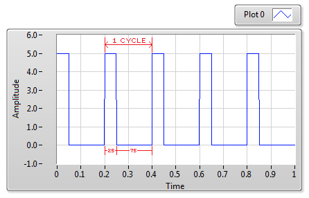
How to measure pulse width ?
So I believe now you know what is pulse width. Every pulse width must have a positive edge and a negative edge. So pulse width is basically a on time between a positive edge and a negative edge. So if we can measure a time between a positive edge detection and next negative edge detection, we can easily measure pulse width with respect to time. So the idea here is that we will use a built in timer of pic16f877a microcontroller and capture compare mode of pic microcontroller is used to detect a positive edge and a negative edge of pulse. So whenever capture pin of pic microcontroller captures a positive edge,we will turn on the timer and as soon as it detect the negative edge, we will turn off the timer. Timer measure by timer will be the width of our PWM. So to understand this tutorial you should know how to use timers of pic microcontroller and how to use capture compare module of pic microcontoller:
Circuit diagram of pulse width measurement using pic microcontroller
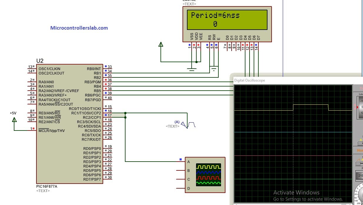
As I have already mentioned, I have used pic16F877A microcontroller in this article. LCD is used to display value of pulse width measurement in terms of time. 16×2 LCD is interfaced with pic microcontroller. LCD is connected with PORTB of microcontroller. I am using proteus for simulation purpose. I am using proteus pulse generator ang given it as a input to ccp module of pic17f877a microcontroller.
Code pulse width measurement using pic microcontroller
sbit LCD_RS at RB1_bit;
sbit LCD_EN at RB2_bit;
sbit LCD_D4 at RB3_bit;
sbit LCD_D5 at RB4_bit;
sbit LCD_D6 at RB5_bit;
sbit LCD_D7 at RB6_bit;

sbit LCD_RS_Direction at TRISB1_bit;
sbit LCD_EN_Direction at TRISB2_bit;
sbit LCD_D4_Direction at TRISB3_bit;
sbit LCD_D5_Direction at TRISB4_bit;
sbit LCD_D6_Direction at TRISB5_bit;
sbit LCD_D7_Direction at TRISB6_bit;

long t2=0; //2nd capture edge (Low)
char periodData[20];
char text[7];
int doub;
int i=0;
double MPH;
void hardwareInit()
{
 CCP1CON = 0x05; // Capture rising edge (101)
 CCP2CON = 0x04; // Switch edge to falling
 TRISC.B2 = 1; // CCP1 pin - RC5 set to input
 TRISC.B1 = 1; // CCP1 pin - RC5 set to input
 TRISB.B0= 0;
 PORTB.B0=0;
 PIE1.B2 = 1; // .. Enable CCP1 interrupt CCP1
 PIE2.B0 = 1; // ... Enable CCP2 interrupt
 PIR1.TMR1IF=0; // Enable timer 1 overflow
 INTCON.PEIE = 1; // ...And global & peripheral interrupts
 INTCON.GIE = 1;
 T1CON= 0b00000000;
 T1CON.TMR1ON= 0; // turn on the timer1
 TMR2IE_bit=1;
}

void interrupt() {
if(PIR1.CCP1IF==1)
{
 T1CON.TMR1ON= 1; // turn on the timer1
 TMR2IE_bit=1;
 PIR1.CCP1IF = 0; // Reset flag
 PIE1.B2 = 0; // .. Enable CCP1 interrupt CCP1
}
if(PIR2.CCP2IF==1)
 { // Flag for 2nd capture (low)
 PIE2.B0 = 0; // ... Enable CCP2 interrupt
 T1CON.TMR1ON=0; // turn off the timer1
 TMR2IE_bit=0;
 t2 = t2 + (TMR1H<<8)|(TMR1L); // Store values for 2nd capture
 MPH = (5007999/t2); // MPH calculation
 TMR1H=0x00;
 TMR1L=0x00;
 PIR2.CCP2IF = 0; // Reset flag
 PIE2.B0 = 1; // Reset CCP interrupt
 PIE1.B2 =1;
 t2=0;
 }
 if (TMR1IF_bit==1)
 {
 t2 = t2+1023;
 TMR1H=0x00;
 TMR1L=0x00;
 TMR1IF_bit==0;
 i++;
 T1CON.TMR1ON= 1; // turn on the timer1
 }
}
void main(){
 Lcd_Init(); // Initialize LCD

Lcd_Cmd(_LCD_CLEAR); // Clear display
 Lcd_Cmd(_LCD_CURSOR_OFF); // Cursor off

hardwareInit();
 T1CON.TMR1ON=0;
 while(1)
 {
 doub = floor(1/MPH * 1000);
 intToStr(doub, periodData); // Output
 intToStr(i, text); // Output
 Lcd_out(1,1,"Period=");
 Lcd_Out(1,8,Ltrim(periodData));
 Lcd_out_cp("ms");
 Lcd_out(2,1,text);
 }
}
So this is code for pulse width measurement using pic microcontroller. Code is written using Mikro C for PIC. Comments are made in code for your understanding.
i have some issue with above code. when i try to compile this code it give the error as “not enough RAM for call stack” what i should do to correct this error ?
im having issues with floor, i dont know if it is a variable or if i need some library for it, can you help me?
Go to View –>Library Manager –> tick on C_math. The error will be solved.
And here is what the compiler says after compiling:
0 1139 Available RAM: 352 [bytes], Available ROM: 8192 [bytes]
0 126 All files Preprocessed in 31 ms
0 122 Compilation Started
0 127 All files Compiled in 15 ms
123 433 Not enough RAM for call stack __Lib_MathDouble.c
0 102 Finished (with errors): 22 Jul 2020, 11:22:02 measurepwm.mcppi
Hola Soy un aficionado y sigo mucho su canal.Señor, por favor ayuda el código no funciona error
0 1139 Available RAM: 352 [bytes], Available ROM: 8192 [bytes]
89 324 Undeclared identifier ‘Lcd_Out_Cp’ in expression MEDIR_PERIODO.c
89 324 Undeclared identifier ‘Lcd_Out_Cp’ in expression MEDIR_PERIODO.c
Muhas gracias
Which compiler you are using? This code will work with MikroC for Pic Compiler
desde Colombia
Muchas gracias por responder, uso mickroc 7.6.0
Then include LCD library from the left sidebar in the library manager
hola, necesito este codigo pero para el compilador xc8, alguna sugerencia de como traducirlo?
check this:
https://microcontrollerslab.com/pwm-using-pic16f877a-microcontroller/
Using INT pin or zero cross detect module
Use of INT pin or pic with zcd module to measure frequency is better
The code doesn’t work for pic16f887 what should I do