In this tutorial, we will see how to use the DAC module of a PIC microcontroller. Digital to Analog converter is an electronics circuit that converts digital values into analog values. In other words, it converts digital voltage levels into an analog voltage levels. Furthermore, we can use DAC modules to generate different types of electrical waveforms such as sawtooth, triangular, sine wave, etc. Its working principle is the exact opposite of an analog to digital converter module.If you want to recall ADC concepts and How to use Analog to digital converter module of pic microcontroller, go through these tutorials:
Recommended Components
The following components are used in this project or are helpful for building it with a PIC microcontroller.
| Component | How it’s used in this project | Buy on Amazon |
|---|
| PIC16F877A microcontroller | Host MCU whose DAC module generates the analog waveforms. | Check Price |
| PICkit 5 programmer/debugger | Flashes the compiled hex file onto the PIC and debugs it. | Check Price |
| Breadboard | Solderless base for wiring the PIC and components together. | Check Price |
| Jumper Wires | Connect power, ground and signal lines between the parts. | Check Price |
As an Amazon Associate we earn from qualifying purchases. Prices and availability are accurate as of the date/time indicated and are subject to change.
PIC Microcontroller Built-in DAC Modules
Almost all Pic microcontroller that belongs to advance series of PIC16 and PIC18 has built-in DAC modules inside a chip. Therefore, we don’t need to use any external electronics circuits with a pic microcontroller. We can easily configure internal digital to analog converter module for generating analog signals. By using registers, a module can be easily configured. We will see examples in the latter part of this tutorial.However, if built-in DAC does not support the specific requirement for your embedded design, we can look for off the chip external DAC ICs such as
DAC0832. But in this tutorial, we will see how to use internal DAC modules of Microchip devices.
DAC Output Selection
In this tutorial, we will use the PIC18F46K22 microcontroller. It has a built-in 5-bit DAC module. Some PIC chips also have 8-bit DAC modules. Like ADC, we also define its resolution with the help of a number of bits. A number of bits defines the number of steps or Resolution. Therefore, a 5-bit converter generates 32 levels. Few pic microcontrollers also have both 5-bit and 8-bit DACs inside a single MCU.
DAC Module PIC18F46K22
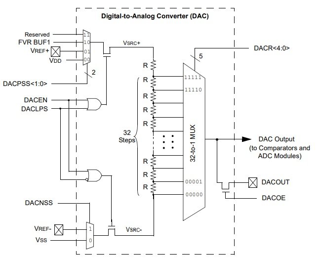
PIC18F46K22 has one 5-bit module. This 5-bit module can provide 32 levels of the output voltage. We can select levels using control registers. We will see later on how to select levels. This picture shows a block diagram of a pic microcontroller. As you can see, it consists of resistor ladder types digital to analog converter. We can control the output voltage of the ladder resistive network with DACR [0:3] bits.

We can use it for the following applications:
- To Generate Variable reference voltage for ADC
- DACOUT Feature with RA2 pin of PIC18F46K22
- Input to the comparator pin
PIC DAC Module Control Registers
It mainly consists of two control registers such as VREFCON1 and VREFCON2. But these are 8-bit registers.
DAC VREFCON1: VOLTAGE REFERENCE CONTROL REGISTER 0

This register used to enable the DAC module, enable DACOUT (RA2) pin and a reference voltage. It is an 8-bit register and out of which 4 and 1 are unused.
- DACEN: This is a DAC module enable bit. You should set this bit to active high. This line will enable the DAC module.
VREFCON1bits.DACEN=1
- DACLPS: This bit is used for positive voltage reference selection. It selects either DAC reference voltage is a positive or negative voltage. We usually use positive reference voltage.
VREFCON1bits.DACLPS=1 // Setting to active selects positive reference voltage
VREFCON1bits.DACLAP=0 //clearing this selects negative reference voltage
- DACOE: It enables and disables the DAC output voltage. We can get DAC output voltage from the RA2 pin of PIC18F46K22 microcontroller. If you want output only for ADC or comparator input voltage, we can disable this feature.
VREFCON1bits.DACOE=1;
With the help of these two bits, we select a positive voltage source for DAC from these three options:
| DACPSS | Positive voltage source |
|---|
| 00 | Vdd |
| 01 | VREF+ |
| 10 | FVR BUF1 output |
Like DAVPSS, DACNSS selects negative voltage reference from these two options:
| DACNSS | Negative voltage source |
|---|
| 1 | Vref |
| 0 | VSS |
DAC VREFCON2: VOLTAGE REFERENCE CONTROL REGISTER 2
- Bit5-7 are unused
- DACR [4:0] bits
These bits select the level of output voltage from the DAC. This module generates output voltage according to this formula.
VOUT = ((VSRC+) - (VSRC-)) * (DACR [4:0]/(2^5)) + VSRC
The value of DAC will be in the range of 0-31 due to 5 bits resolution.Now we will see three example and their codes to generate different waveforms with DAC module of PIC18F46K22 microcontroller.
- Sawtooth Wave Generator
- Triangular wave Generator
- Sine Wave Generator
Use Pic Microcontroller DAC to Generate Triangular Wave Form
In this section, we will see a code to generate a triangular waveform using the DAC module of PIC18F46K22 microcontroller. We can use a simple oscilloscope to see the waveform. RA2 pin which is PORTA pin2 provides DAC OUT signal. This circuit diagram shows the connection of RA2 with an oscilloscope.Sawtooth is a ramp-up voltage that increases from a minimum value to the maximum value linearly. After reaching a maximum value, it suddenly falls to zero voltage. The operating voltage of the PIC18F46K22 microcontroller is 5 volts. Therefore, the ramp-up voltage goes from 0 to 5 volts.

PIC Microcontroller DAC Module Programming
We used MPLAB XC8 Compiler to write a program for this tutorial. You may refer to
getting started with MPLAB XC8 Compiler tutorial.This code generates a sawtooth signal at the output pin.
#include "Config_PIC18F46K22.h"
void internal_16(){
//Clock determined by FOSC in configuration bits
SCS0 = 0;
SCS1 = 0;
//Frequency select bits
IRCF0 = 1;
IRCF1 = 1;
IRCF2 = 1;
//IRCF3 = 1;
//SET PLLx4 OFF
//SPLLEN = 0;
}
void initMain(){
// Run at 16 MHz
internal_16();
// Set PIN D1 as output
TRISAbits.TRISA1 = 0;
TRISAbits.TRISA2 = 0;
// Turn off LED
LATAbits.LATA2 = 0;
LATAbits.LATA1 = 0;
//////////////////////
// Configure DAC
/////////////////////
//VREFCON0bits.FVRS=0b11;
// DAC enabled
DACEN = 1;
// DACOUT pin enabled
DACOE = 1;
// +ve source is Vdd
VREFCON1bits.DACPSS = 0b00;
// -ve source is Vss
DACNSS = 0;
DACLPS = 1;
// Initial output is 0v
VREFCON2bits.DACR=0b0000;
}
void main(void) {
initMain();
int i=0;
while(1)
{
VREFCON2bits.DACR=i; // increasing i value linearly to get linear output voltage
i++;
__delay_us(310);
if(i>=31)
i=0;
}
return;
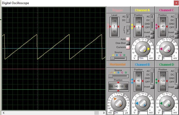
}In this code, we define every DAC control register and its bits according to the information provided in registers sections. For example, we want to generate a sawtooth waveform of frequency 10HZ. The time period of 10Hz will be T= 1/10 = 10ms.In order to get a 10Hz time period, we need to know the sampling period. But if we know a number of bits of DAC, we can easily calculate the DAC sampling period.
Ts=10ms/25
Ts= 10ms/32=312.5µs = 310µs
Therefore, we used a delay of 310µs after every DAC output sample.
PIC DAC Simulation Result

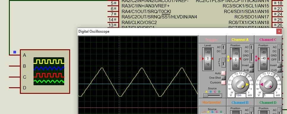
Triangular Wave Generation using PIC DAC Module
In this section, we will see how to generate a triangular waveform with pic microcontroller DAC. A triangular wave consists of ramp-up and ramp-down voltage of equal lengths. For instance, we want to generate a triangular wave of 5Hz frequency.This program will generate a 5Hz wave.
#include "Config_PIC18F46K22.h"
void internal_16(){
//Clock determined by FOSC in configuration bits
SCS0 = 0;
SCS1 = 0;

//Frequency select bits
IRCF0 = 1;
IRCF1 = 1;
IRCF2 = 1;
//IRCF3 = 1;

//SET PLLx4 OFF
//SPLLEN = 0;
}
void initMain(){
// Run at 16 MHz
internal_16();

// Set PIN D1 as output
TRISAbits.TRISA1 = 0;
TRISAbits.TRISA2 = 0;

// Turn off LED
LATAbits.LATA2 = 0;
LATAbits.LATA1 = 0;

//////////////////////
// Configure DAC
/////////////////////

//VREFCON0bits.FVRS=0b11;

// DAC enabled
DACEN = 1;

// DACOUT pin enabled
DACOE = 1;

// +ve source is Vdd
VREFCON1bits.DACPSS = 0b00;

// -ve source is Vss
DACNSS = 0;
DACLPS = 1;

// Initial output is 0v
//DACR = 0;
//VREFCON2bits.DACR=0b1111;
}
void main(void) {
initMain();
int i=0;
while(i<32)
{
VREFCON2bits.DACR=i;
i++;
}
int j=31;
while(j>-1)
{
VREFCON2bits.DACR=j;
j--;
}

return;

}
This code is exactly similar to the last code except for this part.
while(i<32)
{
VREFCON2bits.DACR=i;
i++;
}
int j=31;
while(j>-1)
{
VREFCON2bits.DACR=j;
j--;
}
First, while loop generates rump-up voltage output and second while loop generates a ramp-down voltage as shown in the figure below:

Sine wave generation using DAC Module
Like sawtooth and triangular waves, we can also generate a sine wave using built-in digital to analog converter module of PIC18F46K22 microcontroller. To generate a sine wave, we need to create a sine table inside the code. We use a look-up table that stores values to create a sine wave. Although, you can calculate these values manually using a sine wave formula. But I have used this
sine table calculator.You can generate sine table values according to the size of your DAC module. PIC18F46K22 microcontroller has 5-bit DAC. Therefore, we will use 32 values.
{0,0,1,3,5,7,10,13, 16,19,22,25,27,28,30,31,31,31,30,28,27,25,22,19,16,13,10,7,5,3,1,0};For example, we want to generate a 50Hz sine wave. We can calculate the sampling period similar to the last sections.
T=1/50=20ms
Ts=20ms/32 = 625 micro seconds
That means we will increment the DACOUT value after every 635 microseconds.
Sine wave with DAC Code
- Now copy this copy and open MPLAB IDE.
- Create a new project and select the XC8 compiler from available compilers in MPLAB IDE.
- First set the configuration bits of PIC18F46K22 microcontroller and save these configuration settings inside a header folder name “Config_PIC18F46K22.h”. You can also simply put configuration files inside the main code. But to save space, I used a separate header file.
- Now open main.c file and paste this code. After compiling the code and generate a hex file.
#include "Config_PIC18F46K22.h"
void internal_16(){
//Clock determined by FOSC in configuration bits
SCS0 = 0;
SCS1 = 0;
//Frequency select bits
IRCF0 = 1;
IRCF1 = 1;
IRCF2 = 1;
//IRCF3 = 1;
//SET PLLx4 OFF
//SPLLEN = 0;
}
int sinetable[32]=
{0,0,1,3,5,7,10,13, 16,19,22,25,27,28,30,31,31,31,30,28,27,25,22,19,16,13,10,7,5,3,1,0};
void initMain(){
// Run at 16 MHz
internal_16();
// Set PIN D1 as output
TRISAbits.TRISA1 = 0;
TRISAbits.TRISA2 = 0;
// Turn off LED
LATAbits.LATA2 = 0;
LATAbits.LATA1 = 0;
//////////////////////
// Configure DAC
/////////////////////
//VREFCON0bits.FVRS=0b11;
// DAC enabled
DACEN = 1;
// DACOUT pin enabled
DACOE = 1;
// +ve source is Vdd
VREFCON1bits.DACPSS = 0b00;
// -ve source is Vss
DACNSS = 0;
DACLPS = 1;
// Initial output is 0v
//DACR = 0;
//VREFCON2bits.DACR=0b1111;
}
void main(void) {
initMain();
int i=0;
while(1)
{
VREFCON2bits.DACR=sinetable[i];
i++;
__delay_us(620);
if(i == 33)
i=0;
}
return;
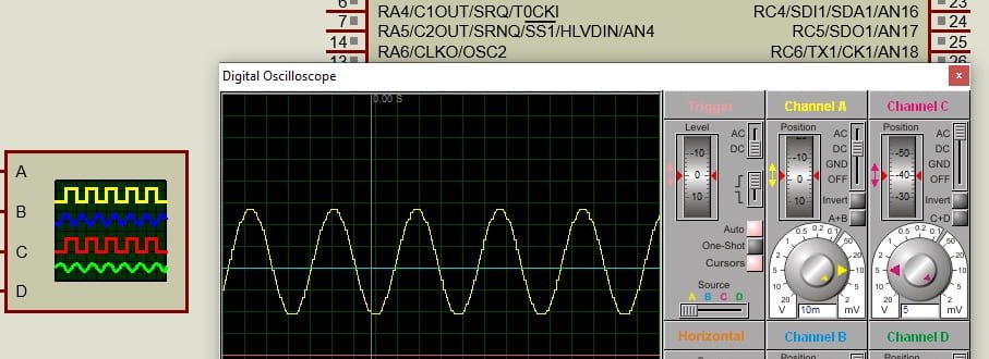
}This code produces a sine wave as shown in this simulation result.

In summary, in this tutorial, we have learned the use of DAC module of pic microcontroller with three examples and their programs.
 We can use it for the following applications:
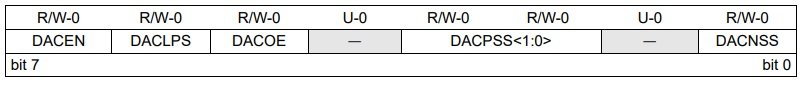 This register used to enable the DAC module, enable DACOUT (RA2) pin and a reference voltage. It is an 8-bit register and out of which 4 and 1 are unused.
 In summary, in this tutorial, we have learned the use of DAC module of pic microcontroller with three examples and their programs.
Hi dears , i just want ask why the output is in (mv)rang not in (V)rang can you answer me please
#include “mcc_generated_files/mcc.h”
#define led1 LATAbits.LATA1
#define led2 LATAbits.LATA2
#define sawtooth VREFCON2bits.DACR
void main(void)
{
SYSTEM_Initialize();
TRISAbits.TRISA1= 0; TRISAbits.TRISA2 = 0;led1=1 ;led2=0;__delay_ms(1000);
led1=1 ;led2=1;
DACEN = 1;// DAC enabled
DACOE = 1;// DACOUT pin enabled
VREFCON1bits.DACPSS = 0b00; // +ve source is Vdd
DACNSS = 0; // -ve source is Vss
DACLPS = 1;
VREFCON2bits.DACR=0b00000;// Initial output is 0v
int i=0;
while (1)
{
sawtooth=i; // increasing i value linearly to get linear output voltage
i++;__delay_us(2010);
if (i>=31) {i=0;}
}
}
—————————————————————
// traingular wave form pic18F45K22 on 1 Mhz
#include “mcc_generated_files/mcc.h”
#define led1 LATAbits.LATA1
#define led2 LATAbits.LATA2
#define sawtooth VREFCON2bits.DACR
void main(void)
{
SYSTEM_Initialize();
TRISAbits.TRISA1= 0; TRISAbits.TRISA2 = 0;led1=1 ;led2=0;__delay_ms(1000);
led1=1 ;led2=1;
DACEN = 1;// DAC enabled
DACOE = 1;// DACOUT pin enabled
VREFCON1bits.DACPSS = 0b00; // +ve source is Vdd
DACNSS = 0; // -ve source is Vss
DACLPS = 1;
VREFCON2bits.DACR=0b00000;// Initial output is 0v
int sinetable[32]=
{0,1,2,3,4,5,6,7,8,9,10,11,12,13,14,15,16,15,14,13,12,11,10,9,8,7,6,5,4,3,2,1,0};
int i = 0;
while (1){
sawtooth= sinetable[i],i++;__delay_us(1000);
if(i==32){i=0;}
}
}
—————————————————————
// #include “mcc_generated_files/mcc.h”
#define led1 LATAbits.LATA1
#define led2 LATAbits.LATA2
#define sawtooth VREFCON2bits.DACR
void main(void)
{
SYSTEM_Initialize();
TRISAbits.TRISA1= 0; TRISAbits.TRISA2 = 0;led1=1 ;led2=0;__delay_ms(1000);
led1=1 ;led2=1;
DACEN = 1;// DAC enabled
DACOE = 1;// DACOUT pin enabled
VREFCON1bits.DACPSS = 0b00; // +ve source is Vdd
DACNSS = 0; // -ve source is Vss
DACLPS = 1;
VREFCON2bits.DACR=0b00000;// Initial output is 0v
int sinetable[32]=
{0,0,1,3,5,7,10,13, 16,19,22,25,27,28,30,31,31,31,30,
28,27,25,22,19,16,13,10,7,5,3,1,0};
int i = 0;
while (1){
sawtooth= sinetable[i],i++;__delay_us(1000);
if(i==32){i=0;}
}
}
—————————————————–
// for traingular wave form pic18F45K22 on 1 Mhz
#include “mcc_generated_files/mcc.h”
#define led1 LATAbits.LATA1
#define led2 LATAbits.LATA2
#define sawtooth VREFCON2bits.DACR
void main(void)
{
SYSTEM_Initialize();
TRISAbits.TRISA1= 0; TRISAbits.TRISA2 = 0;led1=1 ;led2=0;__delay_ms(1000);
led1=1 ;led2=1;
DACEN = 1;// DAC enabled
DACOE = 1;// DACOUT pin enabled
VREFCON1bits.DACPSS = 0b00; // +ve source is Vdd
DACNSS = 0; // -ve source is Vss
DACLPS = 1;
VREFCON2bits.DACR=0b00000;// Initial output is 0v
int i=0;int j=31;
while (1){int i = 0;
while (i<32){sawtooth=i; i++;__delay_us(1000);}
j=31;
while (j=31) {i=0;}
}
}
——————————-