In this tutorial, we will learn how to set an ESP32 to control a servo motor over a web server using the Arduino IDE. We will discover how to control the Servo motor with the ESP32 and how to make a simple web server with a slider to control the position of the servo motor in both directions. The web page will consist of a slider with positions marked from 0 to 180 degrees for rotation. With the help of this slider, we can control the shaft position of the servo motor. Here we will use the Arduino IDE to program the ESP32 Dev Kit module.
Recommended Components
The following components are used in this project or are helpful for building it with the ESP32.
| Component | How it’s used in this project | Buy on Amazon |
|---|---|---|
| ESP32 Development Board (DevKit V1) | The main microcontroller board that runs the project code and controls all connected parts. | Check Price |
| Micro USB Cable | Connects the ESP32 to your computer to upload code and provide power. | Check Price |
| Breadboard | Lets you build the circuit and connect components without soldering. | Check Price |
| Jumper Wires | Used to wire the ESP32 to the other components on the breadboard. | Check Price |
| SG90 servo motor | The motor whose angle you control from the ESP32 web server in this project. | Check Price |
As an Amazon Associate we earn from qualifying purchases. Prices and availability are accurate as of the date/time indicated and are subject to change.
Video demonstration
Prerequisites
We have attached the links below that are prerequisites and whose knowledge is essential for this tutorial:
- Introduction to ESP32 development board
- How to use GPIO pins of ESP32 devkit
- install ESP32 in Arduino IDE and How to program ESP32.
Components Required
We will be using these components for this tutorial:
- ESP32 DOIT DEVKIT Development board
- Few jumper wires
- Servo motor ( we can use any sort of servo motor within the current limit of ESP32)
Interfacing Servo Motor With ESP32
In this section, We will discuss the basics of the servo motor, its types, pinout, and connection layout for interfacing with the ESP32. In order to understand this interfacing circuit, we first need to understand its workings. Let’s start with the basics.
The control of a servo motor is done by providing a series of pulses to control the pin. Almost all servo motors used by hobbyists for their projects work at a frequency of 50 Hz, or the time period of the control signal should be 20 ms. Control signal width defines the position of a shaft and how much it will rotate. The pulse width and position of the shaft are directly proportional to each other. They can rotate from 0 to 180 degrees, depending on pulse width. You can check out the following tutorial to learn more about PWM and its related terms:
The picture shown below provides more details about it.

We don’t need to worry about the workings of the servo motor or how to generate this control signal. We will use the servo library for the ESP32 to provide a control signal. In the next section, we will show how we can add a servo library for the ESP32.
Pinout
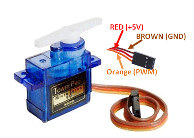
The Servo motor consists of three pins:
- Power pin or (VCC)
- Ground pin (GND)
- Control signal pin (S)
We have provided possible wire colors each pin can have in the table below
| Wire of motor | Possible colors of each wire |
|---|---|
| VCC pin | Red |
| GND pin | Black, or brown |
| Control Signal / PWM pin | Yellow, orange, or white |
Before connecting the servo motor with the ESP32 board, we need to make sure about the operating current of the servo motor. For example, different power servo motors are available on the market. When we are using a low-power servo motor like S0009, we can directly connect it to an ESP32 board. Because its current requirement is less than 10 mA. We will use S0009 in this tutorial, as shown in the picture above. We can also connect SG90 and SG92R series servo motors directly to the ESP32 board. But if we want to use a high-power servo motor with the ESP32, we will need to use a motor driver IC like UNL2003 between these two. In case we want to use multiple Servos with the ESP32, we still have to use the current driver IC.
Schematic diagram
In the schematic diagram provided below, we have used the ESP32 DOIT DEVKIT’s GPIO 13 pin for providing a signal to the servo motor. In case you are using a 36-pin version or any other ESP32 board, make sure to check its pinout and find GPIO pin 13.
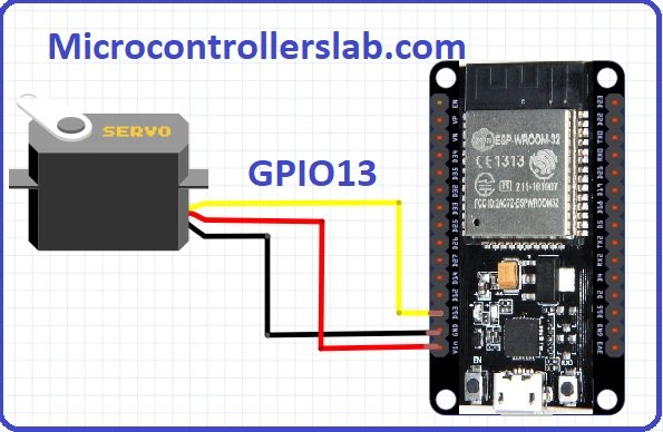
Now, we just make a connection according to this layout on our breadboard. To connect a single servo motor with the ESP32, we will connect according to following configuration:
- Ground Pin >> GND pin of ESP32
- Power pin >> Vin Pin of ESP32
- Control Signal pin >> GPIO 13 of ESP32
We can use any pin of the ESP32 as the PWM (Pulse Width Modulation) pin because we need to provide a PWM signal to the control signal pin of the servo. In this tutorial, we are using the GPIO 13 pin for the PWM signal, as shown in the layout. We can use any other GPIO pin for the control signal. But for this, we need to specify the GPIO pin number inside the code, which we will discuss in the programming section of this guide. One thing to note is that GPIO pins 9, 10, and 11 are not recommended for PWM as they are connected to integrated SPI flash and may not work properly.
Install Servo Library for ESP32
As mentioned before, servo motors are controlled by a series of pulses with a variable pulse width. To generate the series of pulses for controlling the servo motor, we can use the ESP32 servo library. This library helps us control the servo motor without having to write custom code; instead, we will just use the functions provided by this library. Follow these steps to download and install the library. Click on the following link to get this library:
Once we have the servo motor library downloaded on our system, we can follow these simple steps below to install it in the Arduino IDE:
- Locate the downloaded .zip file.
- Use any software to Unzip this downloaded file.
- After extraction, we will get a folder with the name ESP32-Arduino-Servo-Library-Master.
- Change the name of this folder from
ESP32-Arduino-Servo-Library-Masterto ESP32_Arduino_Servo_Library. - Copy this folder to the Arduino library folder. We can find this library folder inside the Arduino installation folder.
- Now open the Arduino IDE; the library for servos will be there. Now we can use it with the ESP32.
Note: In case you have already installed a library for the servo motor using the Arduino IDE library manager, you will still need to install this library manually because the servo motor library present in the Arduino IDE library manager is for boards like the Arduino UNO, Arduino Mega, and STM32. whereas this library is specifically for the ESP32 development boards.
Now we can use this library to control the position of a servo from a web server.
Example code
Upload this sketch in the Arduino IDE, this code rotates the servo for 180 degrees in clockwise direction and for 180 degrees in anti-clockwise direction. The shaft will move from its initial position to 180 degrees and then come back to its initial position at 0 degrees. This is good for testing the servo motor to check whether its working properly or not.
#include <Servo.h>

static const int servoPin = 13;  // defines pin number for PWM

Servo servo1;  // Create object for servo motor

void setup() {
Serial.begin(115200);
servo1.attach(servoPin);  // start the library
}

void loop() {
for(int posDegrees = 0; posDegrees <= 180; posDegrees++) {
servo1.write(posDegrees);
Serial.println(posDegrees);
delay(20);
}

for(int posDegrees = 180; posDegrees >= 0; posDegrees--) {
servo1.write(posDegrees);
Serial.println(posDegrees);
delay(20);
}
}
In this code, we have included the header file of the servo library with the following command:
#include <Servo.h>Then we set the servo motor control pin to the GPIO 13 pin and create a servo1 object. In case you want to use some other pin for the PWM signal of the servo motor, simply replace that pin’s number with 13.
static const int servoPin = 13;  // defines pin number for PWM

Servo servo1;  // Create object for servo motor
Using the void setup() function, we initialized the serial monitor and the servo motor via the servo1 object at pin 13.
void setup() {
Serial.begin(115200);
servo1.attach(servoPin);  // start the library
}
In the void loop function(), we have created a simple for loop of 180 iterations with a delay of 20 ms. This moves the servo motor from its initial position to 180 degrees. The second for loop starts from 180 and decrements to 0, which brings the servo motor back to its initial position.
void loop() {
for(int posDegrees = 0; posDegrees <= 180; posDegrees++) {
servo1.write(posDegrees);
Serial.println(posDegrees);
delay(20);
}

for(int posDegrees = 180; posDegrees >= 0; posDegrees--) {
servo1.write(posDegrees);
Serial.println(posDegrees);
delay(20);
}
}
Controlling Servo with POT Example
This sketch controls the position of the servo motor with the help of a potentiometer. GPIO32 is used as an analog pin. Voltage across POT is mapped using the Analog to Digital Converter based on Pulse Width Modulation, which in response controls the shaft position. For learning more about the ADC of the ESP32, check the following link: ADC of ESP32.
#include <Servo.h>

static const int servoPin = 13;
static const int potentiometerPin = 32;

Servo servo1;

void setup() {
Serial.begin(115200);
servo1.attach(servoPin);
}

void loop() {
int servoPosition = map(analogRead(potentiometerPin), 0, 4096, 0, 180);
servo1.write(servoPosition);
Serial.println(servoPosition);
delay(20);
}
In this code, we first included the Servo.h Library using the header file.
#include <Servo.h>Then we defined pin 13 for controlling the servo motor and pin 32 for mapping voltage across the potentiometer. In case you want to use some other pin for the PWM signal of the servo motor or for measuring the voltage across the potentiometer using ADC, simply replace that pin’s number with 13 or 32, respectively.
static const int servoPin = 13;
static const int potentiometerPin = 32;
Then we created an object with the name servo1 and initialized the serial monitor and servo pin.
Servo servo1;

void setup() {
Serial.begin(115200);
servo1.attach(servoPin);
}
In the last section of the void loop() function, we used the servoPosition variable to map the voltage across the servo motor and create a pulse width based on the voltage of the potentiometer.
void loop() {
int servoPosition = map(analogRead(potentiometerPin), 0, 4096, 0, 180);
servo1.write(servoPosition);
Serial.println(servoPosition);
delay(20);
}
The servo1.write(servoPosition) function changes the position of the object servo1 connected to pin 13 to the updated position based on the potentiometer’s voltage, which is then converted to pulses via ADC. At last, we display this on the serial monitor to observe the real-time position of the servo motor.
Now, we will see an example of how we can control a servo motor using the web server, and after that, we will explain the workings of the code and how to make a web server with esp32.
Creating Servo Web server with ESP32
After making the connection according to the schematic diagram and installing the library, we will copy this code to the Arduino IDE and upload it to the ESP32 DOIT DEVKIT.
/*********
Microcontrollerslab.com
you can get more projects about ESP32
Microcontrollers lab
*********/

#include <WiFi.h>
#include <Servo.h>

Servo ObjServo; // Make object of Servo motor from Servo library
// Objects are made for every servo motor,we want to control through this library

static const int ServoGPIO = 13; // define the GPIO pin with which servo is connected

// Variables to store network name and password
const char* ssid = "PTCL-BB"; // Enter your network name
const char* password = "5387c614"; //Enter your network password

// Set the server port nunber to deafualt 80
WiFiServer server(80);

// this variable header stores the HTTP requests data
String header;

// These variables used to store slider position
String valueString = String(0);
int positon1 = 0;
int positon2 = 0;

void setup()
{
Serial.begin(115200); //define serial commuination with baud rate of 115200
ObjServo.attach(ServoGPIO); // it will attach the ObjServo to ServoGPIO pin which is 13
Serial.print("Making connection to "); // it will display message on serial monitor
Serial.println(ssid);
WiFi.begin(ssid, password);
while (WiFi.status() != WL_CONNECTED) {
delay(500);
Serial.print(".");
}
// These lines prints the IP address value on serial monitor
Serial.println("");
Serial.println("WiFi connected.");
Serial.println("IP address: ");
Serial.println(WiFi.localIP());
server.begin(); // It will start the servo motor with given position value.
}

void loop(){
WiFiClient client = server.available(); // Listen for incoming clients

if (client)
{ // If a new client connects,

String header = client.readStringUntil('\r');
client.println("HTTP/1.1 200 OK");
client.println("Content-type:text/html");
client.println("Connection: close");
client.println();

// Display the HTML web page
client.println("<!DOCTYPE html><html>");
client.println("<head><meta name=\"viewport\" content=\"width=device-width, initial-scale=1\">");
client.println("<link rel=\"icon\" href=\"data:,\">");
// CSS to style the on/off buttons
// Feel free to change the background-color and font-size attributes to fit your preferences
client.println("<style>body { text-align: center; font-family: \"Trebuchet MS\", Arial; margin-left:auto; margin-right:auto;}");
client.println(".slider { width: 300px; }</style>");
client.println("https://ajax.googleapis.com/ajax/libs/jquery/3.3.1/jquery.min.js");

// Web Page
client.println("</head><body><h1>ESP32 with Servo</h1>");
client.println("<p>Position: <span id=\"servoPos\"></span></p>");
client.println("<input type=\"range\" min=\"0\" max=\"180\" class=\"slider\" id=\"servoSlider\" onchange=\"servo(this.value)\" value=\""+valueString+"\"/>");

client.println("<script>var slider = document.getElementById(\"servoSlider\");");
client.println("var servoP = document.getElementById(\"servoPos\"); servoP.innerHTML = slider.value;");
client.println("slider.oninput = function() { slider.value = this.value; servoP.innerHTML = this.value; }");
client.println("$.ajaxSetup({timeout:1000}); function servo(pos) { ");
client.println("$.get(\"/?value=\" + pos + \"&\"); {Connection: close};}</script>");

client.println("</body></html>");

//GET /?value=180& HTTP/1.1
if(header.indexOf("GET /?value=")>=0)
{
positon1 = header.indexOf('=');
positon2 = header.indexOf('&');
valueString = header.substring(positon1+1, positon2);

//Rotate the servo
ObjServo.write(valueString.toInt());
Serial.println(valueString);
}

header = "";
client.stop();
Serial.println("Client disconnected.");
Serial.println("");
}
}
Note: Before you upload this code, make sure to change your network credentials according to your WiFi name and password.

After uploading this code to the ESP32 board, we need to open the serial monitor and note down the IP address, as shown in the picture above.

We will copy this IP address and open it using our web browser. After opening this IP address, we will see the following webpage with the title “ESP32 with Servo” and a slider:

We can control the position of the servo’s shaft with the help of this slider.
This slider can move in the right or left position, which will rotate the motor in the clockwise or anti-clockwise direction, respectively.
ESP32 Web Server using Arduino
For learning more about creating webservers using Arduino IDE you can check the following link:
Code working
Now we will see how the code works. The main working of the code is given below:
- It will create a web page with a slider. Any web client can connect to this web page through an IP address we get on the serial monitor of the Arduino IDE.
- The slider can control the position of the shaft between 0 and 180 degrees. A web client can move the slider in the left or right position to control the shaft position.
- Once a web client opens the web page, it does not need to update the page, again and again, to update the position of the slider because we use the AJAX javascript file to refresh the web page automatically when a user updates the position of the slider.
- This web page sends HTTP requests to the ESP32 to update the position of a servo motor.
Code Explanation
The following code lines add the libraries of the WiFi driver and the servo motor.
#include <WiFi.h>   // add library of WiFi for ESP32
#include <Servo.h> // add library of Servo for ESP32
The line below makes an object of the servo motor from the Servo library. Objects are made for every servo motor if we want to control multiple servos through this single servo library. We can create up to 12 objects.
Servo ObjServo; // create object with name ObjServoThis line defines the name of the GPIO pin to which we have connected the servo motor.
static const int ServoGPIO = 13; // Pin number to which control signal pin is connectedThese variables store the network name and password for connecting the ESP32 to a WiFi network. Make sure to replace these credentials according to your WiFi network configuration.
const char* ssid = "PTCL-BB"; // Enter your network name
const char* password = "5387c614"; //Enter your network password
WiFiServer server(80);// Set the server port nunber to deafualt 80
This variable header stores the HTTP request data received from a web client.
String header;These variables store previous and updated values of servo position and slider position.
String valueString = String(0);
int positon1 = 0;
int positon2 = 0;
The first line defines the baud rate of serial communication, and the second line attaches the GPIO pin to the object of the servo motor that we created earlier.
Serial.begin(115200); //define serial communication with baud rate of 115200
ObjServo.attach(ServoGPIO); // it will attach the ObjServo to ServoGPIO pin which is 13
This part of the code is used for connecting the ESP32 to a WiFi router. The ESP32 connects to the WiFi router and displays the IP address on the serial monitor.
Serial.print("Making connection to "); // it will display message on serial monitor
Serial.println(ssid);
WiFi.begin(ssid, password);
while (WiFi.status() != WL_CONNECTED) {
delay(500);
Serial.print(".");
}
// These lines prints the IP address value on serial monitor
Serial.println("");
Serial.println("WiFi connected.");
Serial.println("IP address: ");
Serial.println(WiFi.localIP());
server.begin(); // It will start the servo motor with given position value.
}
Before explaining the code inside the loop function, we will explain the HTML part of this code, which we have used inside the main function. This HTML part of the code is used to create the slider and web page layout.
Creating a Web page
This HTML web page is responsible for making a range slider and updating the web page automatically. If you are not familiar with HTML and CSS, you can visit this website to learn the basics of HTML and CSS. The following code is used for an HTML page:
<!DOCTYPE html>
<html>
<head>
<meta name="viewport" content="width=device-width, initial-scale=1">
<link rel="icon" href="data:,">
<style>
body {
text-align: center;
font-family: "Trebuchet MS", Arial;
margin-left:auto;
margin-right:auto;
}
.slider {
width: 300px;
}
</style>
https://ajax.googleapis.com/ajax/libs/jquery/3.3.1/jquery.min.js
</body>
</html>
Creating a range slider
To create a range slider in HTML, we use <input> and </input> tags. The following line creates a range slider with <input> and </input> tags.
<input type="range" min="0" max="180" class="slider" id="servoSlider"
onchange="servo(this.value)"/>- The type defines the type of slider because we want to create a range slider; therefore, we used “range” and defined a minimum value of 0 and a maximum value of 180.
- The feature “onchange” calls a JavaScript function, which is explained below.
We have provided the JavaScript code below, which is used to update the web page automatically and send an HTTP request with the values of the slider position. We write JavaScript functions between the <script> and </script> tags. This code updates the web page with the slider position value.
var slider = document.getElementById("servoSlider");
var servoP = document.getElementById("servoPos");
servoP.innerHTML = slider.value;
slider.oninput = function() {
slider.value = this.value;
servoP.innerHTML = this.value;
}
$.ajaxSetup({timeout:1000});
 function servo(pos) {
 $.get("/?value=" + pos + "&");
 {Connection: close};
 }
The following lines get the values of the slider position from HTTP request data, which is stored in the header string. The ObjServo.write() function rotates the servo motor according to the received value of the slider position.
if(header.indexOf("GET /?value=")>=0)
{
positon1 = header.indexOf('=');
positon2 = header.indexOf('&');
valueString = header.substring(positon1+1, positon2);


ObjServo.write(valueString.toInt());
Serial.println(valueString);
}
Conclusion
In summary, we have learned the following in this tutorial:
- What is a servo motor.
- How to connect a servo motor with ESP32
- How to control the servo motor with the potentiometer
- How to control the servo motor from a web page using a slider.
Related Projects:
If you liked this article and enjoyed reading it, then you will surely like these articles provided in the list below:
- ESP32 Web Server Arduino IDE- Control GPIO Outputs
- ESP32/ESP8266 Momentary Switch Web Server: Control GPIO Outputs
- Displaying Images in ESP32 and ESP8266 Web Server
- ESP32/ESP8266 Web Server to Control Outputs with a Timer (Pulse Width)
- Password protected ESP32 web server in Arduino IDE
- Accessing ESP32 web server from anywhere in the world
- DHT11 and DHT22 web server to display temperature and humidity values on the web page
- ESP32 tutorials and projects
Hi,
I think they started a very nice project.
I have a similar application.
however, i need two sliders.
Unfortunately I have not yet been able to program a second independent slider because I don’t really have much of a clue in html or CSS.
what do I have to change the second time I call the slider? variables? Classen?
thank you