CCPM Servo Tester is a small compact module for monitoring the performance of servo motors such as consistency, direction, and ESC(Electrical Speed Controller). CCPM Servo Consistency Master/Servo Tester is a low-power, cost-effective device which can examine three servo motors at a time. The tester requires a maximum of 6 volts for normal functioning. It also has an electric speed controller (ESC), which is used to check the motor’s current directions. The tester does not need a transmitter or receiver to generate signals. One can use it to check the faulty servo motors before using them in different projects.
This tutorial will discuss the pinout, pin configuration details, features, specifications, and applications of CCPM consistency Master.

Recommended Components
The following parts are used in this article, along with a generic electronics kit that is handy for building and testing the circuit.
| Component | How it’s used | Buy on Amazon |
|---|---|---|
| CCPM servo / ESC tester | The CCPM servo consistency master / motor tester this article covers. | Check Price |
| Electronic component assortment kit (1390 pcs) | A handy assortment of resistors, capacitors, LEDs, diodes and transistors for building circuits. | Check Price |
| Digital multimeter (AstroAI) | Measures voltage, current, resistance and checks continuity while you build and debug. | Check Price |
| Breadboard | Solderless base for prototyping the circuit. | Check Price |
| Jumper Wires | Make the connections on the breadboard. | Check Price |
As an Amazon Associate we earn from qualifying purchases. Prices and availability are accurate as of the date/time indicated and are subject to change.
CCPM Servo Tester Components
The components of the Consistency Master are presented are shown in the figure below. The header on the left hand side is a output connector to connect 3 servo motors. While the connector on the right hand side is a input connector which is used to provide power supply to tester and input signal for servo’s.
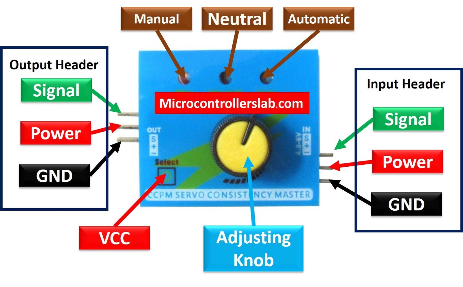
- Input Block: The input is to connect the power source and input signal.
- Output Block: The output block is where the motor to be tested is to be attached or to the output signal.
- Speed Knob: The tester comes with a speed knob to manually rotate the motors. It produces a 1.5ms±0.5ms output signal.
- Mode Selection Switch: The tester has three modes. So, a switch is provided to select the mode.
- LED Indicator: The respective LED will light up when the respective mode is selected.
CCPM Servo Tester Pinout
Following diagram shows the pinout of the CCPM Servo Tester:

Pin Configuration
The pin configuration of CCPM servo tester are mentioned in the table below:
| Pin Name | Function |
|---|---|
| INS | Signal Input pin |
| IN+ | Power Supply pin |
| IN- | Ground pin |
| OUT_S | 3×3 connector to connect three signal outputs to three servo motors |
| OUT+ | Servo motor power pin |
| OUT- | Servo motor ground pin |
Features and Specifications of CCPM Servo Consistency Master/Servo Tester
- Operating Voltage: 4.8 – 6 Volts
- Operating Temperature: -40 – 800C
- Signal Output: 1.5ms±0.5ms
- Output Current: >15 mA (5 mA per berg)
- 3X3 berg to connect 3 servo motors simultaneously
- 3 modes of operations
- A knob to rotate servo manually
- Tiny box with dimensions in millimeters
How to use CCPM Servo Tester and its Modes
The wiring is quite effortless. Connect a power source not more than 6 Volts to the input block of the tester. The servo motor under test is connected to the output block of the tester. Now, select the mode of operation by pressing the mode selection switch. The motion of the motors depends on the mode of selection.
Automatic mode
If we select the automatic mode, the servo motor will rotate to and from its maximum angle automatically as soon as the tester is powered. For it rotates similar to window wipers.
Neutral mode
If we select the neutral mode, the motor will move to its factory-set position.
Manual mode
If we select the manual mode, we can rotate the servo motor with the help of an adjustable knob of the tester at our own pace.
As shown in the components figure, the three LED indicators are provided with servo tester module so that the user can indentify in which mode the tester is operating.
The following figure shows the connection diagram of a servo motor CCPM servo tester.
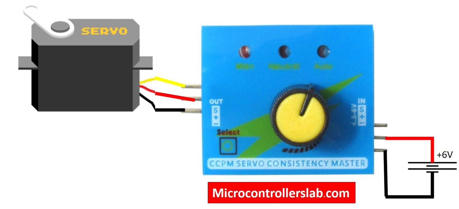
Testing Steps
First make connections according to above connection diagram. Now switch on power supply. Tester can be in any one of three modes depending on selector switch position. For example, when you connect servo motor and powers the tester with 6V power supply, the servo tester was in manual mode. But normally, it will be in manual mode and LED indicator determines in which mode the test is.
In manual mode, when we rotate the speed knob servo motor also rotates either clockwise or anti-clockwise according to the speed and directon of rotation of adjusting Knob.
Now if you press the mode selector switch, CCPM tester will change its mode from manual to a neutral mode and neutral indicator LED turns on. Morover, the connected servo motor will come to its neutral position.
The last mode is an automatic mode in which we don’t need to use an adjusting knob. Now if you press the selector switch again, servo test will change its mode to automatic mode. Servo motor rotates automatically in both clockwise and anticlockwise directions.
CCPM Alternate Options
- EK20907 Servo Tester
- STV35 Servo Tester
Applications
- Servo motor Testing
- Fault detection
- Electric Speed Control Testing
- Drones motor testing
- Toy Helicopters servo testing
2d Diagram
The 2D model depicting the physical dimensions of the CCPM Consistency Master is shown below:

Related Articles:
- SG-90 Servo Motor Interfacing with TM4C123 Launchpad
- SERVO MOTOR interfacing with PIC16F877A MICROCONTROLLER
- ESP32 Web Server Control Servo motor with Arduino IDE
- Servo motor control and interfacing with Arduino
- Web Controlled Servo Motor using Arduino and esp8266
- servo motor interfacing with 8051 using keil compiler
- joystick based servo motor control using arduino
- Servo Motor construction working and control