In this tutorial, we will learn to interface SG-90 servo motor with TM4C123 Tiva Launchpad. To interface actuator devices such as a servo motor with TM4C123, we should use general purpose input-output pins of TM4C123GH6PM microcontroller as digital output pins. Because we will provide a control signal from the Tiva Launchpad to the servo motor to control its rotation or movement. We will use Keil uvision to write a program of TM4C123 which will control SG-90 servo motors.

Recommended Components
The following components are used in this project or are helpful for getting started with TM4C123 Tiva C LaunchPad development.
| Component | How it’s used in this project | Buy on Amazon |
|---|---|---|
| TM4C123G Tiva C LaunchPad | The Tiva C board generating the servo control pulse. | Check Price |
| Micro USB Cable | Connects the LaunchPad’s onboard debugger to your PC for programming and power. | Check Price |
| SG90 Servo Motor | The micro servo whose angle is set by the PWM signal. | Check Price |
| Breadboard | Solderless breadboard for building the circuit. | Check Price |
| Jumper Wires | For wiring the servo to the LaunchPad. | Check Price |
As an Amazon Associate we earn from qualifying purchases. Prices and availability are accurate as of the date/time indicated and are subject to change.
Pre-requisites:
- How to Download and Install Keil uVision for ARM and 8051
- Getting started with Keil uVision: Write your first Program for Tiva LaunchPad
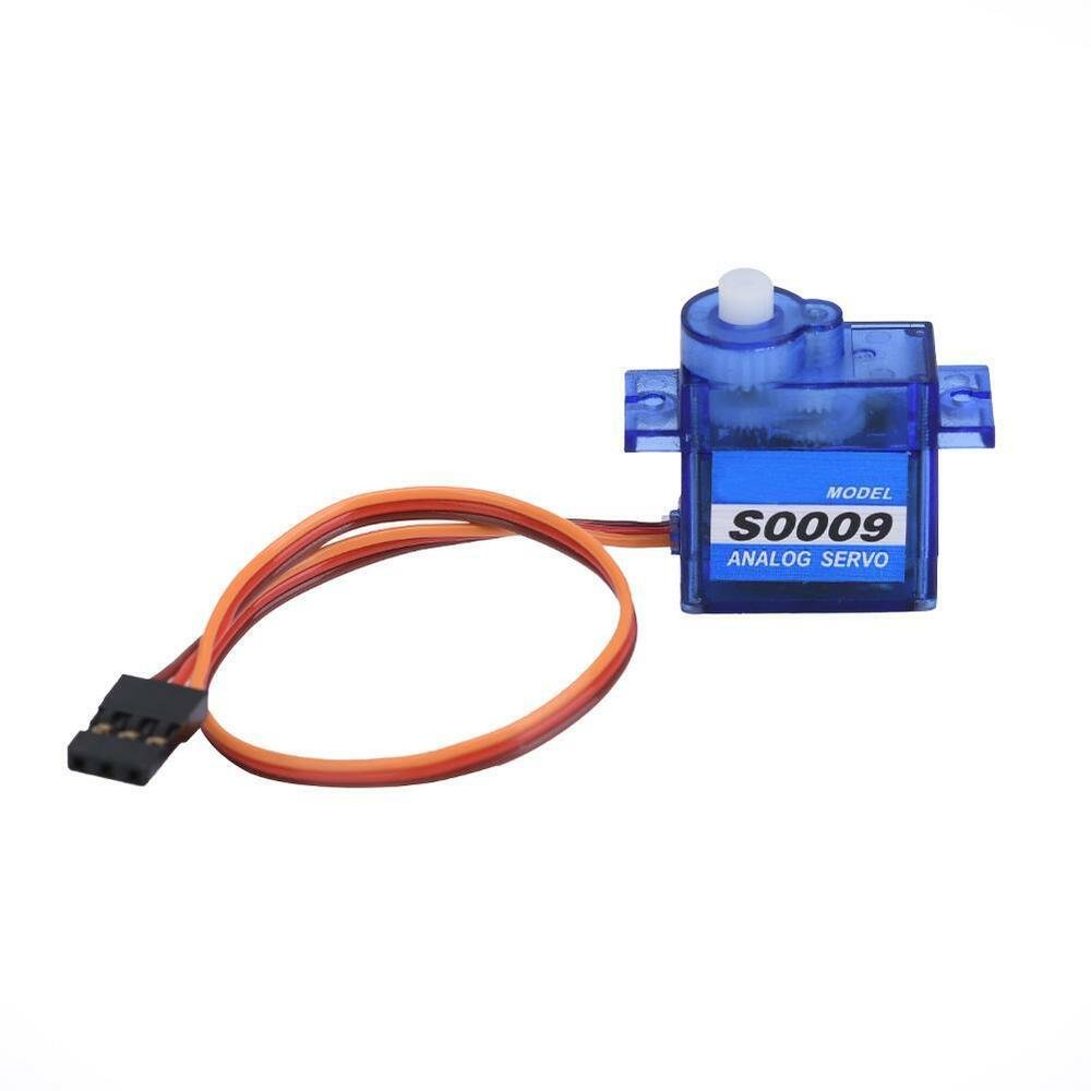
SG-90 Servo Motor Introduction
SG90 is a low cost and high output power servo motor. It can rotate up to 180 degrees and each step can be of maximum 90 degrees. Moreover, it is small enough that it can easily fit into your robotics ARM or obstacle avoidance robotics projects. On top of that, it requires only one output pulse signal to control its movement.
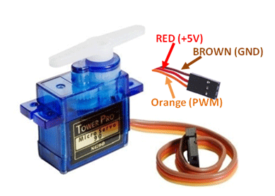
Pinout
The following figure shows the pinout diagram of SG90 servo motor. It consists of three pins only such as PWM, ground and Vcc pin. Brown, orange and red wires are GND, Vcc and PWM pins respectively. Details and functionality of each pin is listed in the next section.
Pin Configuration Details
Vcc and ground, as their name suggests, are the power supply pins which are used to power servo motor. Only 5 volts of power signal is required to power this motor. Mostly microcontrollers or development boards have onboard 5 volts supply which we can use to power SG90 servos.
But the only issue with TM4C123 Tiva Launchpad is that it does not contain onboard 5 volts power source. Therefore, you should use an external 5 volt power supply to power the SG90 servo motor. But make sure to common ground terminals of TM4C123, external 5 volt power supply and servo motor.
PWM Pin is an input pin of a servo motor. We provide a PWM output signal from the TM4C123 microcontroller to drive the servo motor through this pin.
This table briefly described all three pins:
| Wire of motor | Possible colors of each wire |
|---|---|
| Vcc pin | Red |
| GND pin | Black, or brown |
| Control Signal / PWM pin | Yellow, orange, or white |
How to control Servo motor rotator movement?
The position of the servo rotator is directly related with the width pulse applied to the PWM signal of the motor.
To control rotation, we apply pulses to the PWM pin of the servo motor. The frequency of the PWM signal should be 50Hz. That means the control signal pulse should be applied to the PWM pin every 20ms duration. The width of the pulse has a direct relation with the angular position of the motor.
For SG90 type servo motors, the pulse width of 1ms crosspond to 0 degree rotation, 1.5ms to 90 degree and 2ms to 180 degree rotation.
Hence, the pulse width between 1ms to 2ms controls the shaft position of the servo motor between 0 to 180 degrees.
Note: This pulse duration may be different for different types of servo motors.
Controlling Servo motor with TM4C123 Tiva Launchpad
In this section, we will see how to interface a servo motor with TM4C123 Tiva C Launchpad. As we mentioned earlier, to control the position of the servo motor, we need to provide a pulse of a specific duration to the control pin of the servo motor. Therefore, we will use a GPIO pin of TM4C123GH6PM microcontroller to provide a pulse of 1ms, 1.5ms, and 2ms. Firstly, you should know how to use GPIO pins of TM4C123 Tiva Launchpad.
You can read about our previously posted articles on GPIO pins:
Connection Diagram
Now make connections with TM4C123 and SG-90 servo motor according to this schematic diagram. In this tutorial, we use the PA4 of the Tiva Launchpad to provide a pulse signal to a servo motor. Moreover, you should power SG-90 with a separate 5 volts power supply.

Code in Keil uvision
In this demo code, we create three functions such as servo0, servo90, servo180, which rotate servo motor 0, 90 and 180 degrees respectively. Pulse signal is provided through a PA4 pin of TM4C123 microcontroller.
This code is written in Keil uvision. You can simply copy this code and create a new project in keil uvision. If you are a beginner with TM4C123 and did not use Keil IDE before, you can read these getting started guides:
/*header files for TM4C123 device*/
#include "TM4C123GH6PM.h"
#include <stdio.h>


#define two_second 1000000 // two second delay from micro second delay function

/*Function prototype for microsecond delay function and servo rotation*/
void Delay_MicroSecond(int time); // generates delay in microseconds
void Servo_0_Degree(void);  // 3% duty cycle of 50Hz pulse
void Servo_90_Degree(void); // 7% duty cycle of 50Hz pulse
void Servo_180_Degree(void);// 12% duty cycle of 50Hz pulse

/* main code to control servo motor angular movement */
int main(void)
{
 /* PA4 as a digital output signal to provide trigger signal */
	  SYSCTL->RCGCGPIO |= 1;      /* enable clock to PORTA */
	  GPIOA->DIR |=(1<<4);         /* set PA4 as a digial output pin */
	  GPIOA->DEN |=(1<<4);         /* make PA4 as digital pin */
	  while(1)
	{

      Servo_0_Degree();
      Delay_MicroSecond(two_second);
      Servo_90_Degree();
      Delay_MicroSecond(two_second);
      Servo_180_Degree();
       Delay_MicroSecond(two_second);
	}

}

/* This function generate a 3% duty cycle from 20ms PWM signal or 50Hz*/
void Servo_0_Degree(void)
{
   int i=0;
	for(i=0; i<50; i++)
	{
	  /* Given 10us trigger pulse */
	  GPIOA->DATA |= (1<<4); /* make control  pin high */
	  Delay_MicroSecond(600); /*0.6ms seconds delay */
	  GPIOA->DATA &= ~(1<<4); /* make control  pin low */
	  Delay_MicroSecond(19400); /*1.94ms seconds delay */
  }
}
/* This function generate a 7% duty cycle from 20ms PWM signal or 50Hz*/
void Servo_90_Degree(void)
{
   int i=0;
	 for(i=0; i<50; i++)
    {
	/* Given 10us trigger pulse */
	  GPIOA->DATA |= (1<<4); /* make control  pin high */
	  Delay_MicroSecond(1400); /*1.4ms seconds delay */
	  GPIOA->DATA &= ~(1<<4); /* make control  pin low */
	  Delay_MicroSecond(18600); /*1.86ms seconds delay */
		}
}
/* This function generate a 12% duty cycle from 20ms PWM signal or 50Hz*/
void Servo_180_Degree(void)
{
   	int i=0;
	  for(i=0; i<50; i++)
    {
	  /* Given 10us trigger pulse */
	  GPIOA->DATA |= (1<<4); /* make control  pin high */
	  Delay_MicroSecond(2400); /*2.4ms seconds delay */
	  GPIOA->DATA &= ~(1<<4); /* make trigger  pin high */
	  Delay_MicroSecond(17600); /*1.76ms seconds delay */
		}
}


/* Create one microsecond second delay using Timer block 1 and sub timer A */

void Delay_MicroSecond(int time)
{
    int i;
    SYSCTL->RCGCTIMER |= 2;     /* enable clock to Timer Block 1 */
    TIMER1->CTL = 0;            /* disable Timer before initialization */
    TIMER1->CFG = 0x04;         /* 16-bit option */
    TIMER1->TAMR = 0x02;        /* periodic mode and down-counter */
    TIMER1->TAILR = 16 - 1;  /* TimerA interval load value reg */
    TIMER1->ICR = 0x1;          /* clear the TimerA timeout flag */
    TIMER1->CTL |= 0x01;        /* enable Timer A after initialization */

    for(i = 0; i < time; i++)
    {
        while ((TIMER1->RIS & 0x1) == 0) ;      /* wait for TimerA timeout flag */
        TIMER1->ICR = 0x1;      /* clear the TimerA timeout flag */
    }
}

/* This function is called by the startup assembly code to perform system specific initialization tasks. */
void SystemInit(void)
{
    __disable_irq();    /* disable all IRQs */

    /* Grant coprocessor access */
    /* This is required since TM4C123G has a floating point coprocessor */
    SCB->CPACR |= 0x00F00000;
}
How does Code works?
As discussed earlier, to control angular position of the servo motor, we apply pulses of different duty cycles to control pin for every 20ms. That means the frequency of the PWM signal should be 50Hz. The duty cycle of 50Hz PWM signal determines the angular position of the motor. Practical control of this motor is between +90 degrees and -90 degrees. Hence, to control shaft position, we need to apply a duty cycle having pulse width between 0.6ms to 2.4ms. Therefore, we create three functions to apply 3%, 7% and 12% duty cycle pulses from TM4C123 to control pin of the servo motor.
/* This function generate a 3% duty cycle from 20ms PWM signal or 50Hz*/
void Servo_0_Degree(void)
{
   int i=0;
	for(i=0; i<50; i++)
	{
	  /* Given 3% duty cycle trigger pulse */
	  GPIOA->DATA |= (1<<4); /* make control  pin high */
	  Delay_MicroSecond(600); /*0.6ms seconds delay */
	  GPIOA->DATA &= ~(1<<4); /* make control  pin low */
	  Delay_MicroSecond(19400); /*1.94ms seconds delay */
  }
}
/* This function generate a 7% duty cycle from 20ms PWM signal or 50Hz*/
void Servo_90_Degree(void)
{
   int i=0;
	 for(i=0; i<50; i++)
    {
	/*  Given 7% duty cycle trigger pulse */
	  GPIOA->DATA |= (1<<4); /* make control  pin high */
	  Delay_MicroSecond(1400); /*1.4ms seconds delay */
	  GPIOA->DATA &= ~(1<<4); /* make control  pin low */
	  Delay_MicroSecond(18600); /*1.86ms seconds delay */
		}
}
/* This function generate a 12% duty cycle from 20ms PWM signal or 50Hz*/
void Servo_180_Degree(void)
{
   	int i=0;
	  for(i=0; i<50; i++)
         {
	  /*  Given 12% duty cycle trigger pulse */
	  GPIOA->DATA |= (1<<4); /* make control  pin high */
	  Delay_MicroSecond(2400); /*2.4ms seconds delay */
	  GPIOA->DATA &= ~(1<<4); /* make trigger  pin high */
	  Delay_MicroSecond(17600); /*1.76ms seconds delay */
         }
}
To get a precise one microsecond delay from TM4C123GH6PM microcontroller, we use Timer1 and sunblock A that is Timer1A of TM4C123. This Delay_MicroSecond() function generates a delay in multiples of one microseconds. The input argument to this function defines the number of microseconds delay.
We have previously posted an article on how to generate delay using TM4C123 timers. You can read here:
* Create one microsecond second delay using Timer block 1 and sub timer A */

void Delay_MicroSecond(int time)
{
    int i;
    SYSCTL->RCGCTIMER |= 2;     /* enable clock to Timer Block 1 */
    TIMER1->CTL = 0;            /* disable Timer before initialization */
    TIMER1->CFG = 0x04;         /* 16-bit option */
    TIMER1->TAMR = 0x02;        /* periodic mode and down-counter */
    TIMER1->TAILR = 16 - 1;  /* TimerA interval load value reg */
    TIMER1->ICR = 0x1;          /* clear the TimerA timeout flag */
    TIMER1->CTL |= 0x01;        /* enable Timer A after initialization */

    for(i = 0; i < time; i++)
    {
        while ((TIMER1->RIS & 0x1) == 0) ;      /* wait for TimerA timeout flag */
        TIMER1->ICR = 0x1;      /* clear the TimerA timeout flag */
    }
}
Inside the main code, we configure the PORTA PA4 pin of TM4C123 as a digital output pin by enabling system clock to PORTA. Also, setting PA4 as a digital output pin.
* PA4 as a digital output signal to provide trigger signal */
SYSCTL->RCGCGPIO |= 1;      /* enable clock to PORTA */
GPIOA->DIR |=(1<<4);         /* set PA4 as a digial output pin */
GPIOA->DEN |=(1<<4);         /* make PA4 as digital pin */
Code inside the while(1) will keep executing repeatedly. Furthermore, inside the while(1) loop, we call Servo_0_Degree(), Servo_90_Degree(), and Servo_180_Degree() functions to control the angular position of the motor according to the functionality of these functions as defined above.
while(1)
{

Servo_0_Degree();
Delay_MicroSecond(two_second);
Servo_90_Degree();
Delay_MicroSecond(two_second);
Servo_180_Degree();
Delay_MicroSecond(two_second);
}
In summary, this code first sets the angular position to 0 degrees, followed by 90 degrees and back to start position of 180-degree shift that is an angle between +90 and -90 degree.
Hardware Demo
In this hardwar demo, as you can see that the servo motor rotates from +90 to -90 degrees. PA4 pin of TM4C123 Tiva Launchpad provides control signal to SG-90 servo.
Conclusion
In this tutorial, we learned how to interface the SG-90 servo motor with the TM4C123 Tiva Launchpad by utilizing the general-purpose input-output (GPIO) pins of the TM4C123GH6PM microcontroller. By configuring these pins as digital outputs, we were able to send precise control signals to the servo motor, enabling accurate rotation and movement. Through the use of Keil uVision, we developed a program to manage the servo motor’s actions effectively. This guide provides a solid foundation for integrating and controlling servo motors in your embedded projects, enhancing your ability to develop sophisticated and responsive actuator-driven systems.
Related Tutorials:
- ESP32 Web Server Control Servo motor with Arduino IDE
- SERVO MOTOR interfacing with PIC16F877A MICROCONTROLLER
- Web Controlled Servo Motor using Arduino and esp8266
- servo motor interfacing with 8051 using Keil compiler
- joystick based servo motor control using Arduino
- Servo motor control and interfacing with Arduino
I don’t understand why the signal widths are 0.6ms, 1.4ms, and 2.4ms in your code since you defined them to be 1ms, 1.5ms, and 2ms. Can you explain?
Also:
Delay_MicroSecond(19400); /*1.94ms seconds delay */
I think it is 19.4ms, and you have to correct other ones too.
Can a use sevro motor with push button 90 degrees , if my finger into the button goes 90 degrees and stop else 0 degrees , help me if u can guys
Interface a servo motor (by connecting its signal control pin) with any PWM pin of the TIVA C Series LaunchPad and program it to control its rotation by varying a potentiometer, interfaced to any analog pin. (Reference for servo control PWM signal is also attached with this assignment). You may need external power supply to power up the motor. how i could do that
Hey, I was reading the datasheet and the timers also have a PWM option in them. Is there a reason why you decided to not use them? (I am using this code as a guide for school and I am completely lost in PWM controls out here).