In this project, we will build an ESP32 GPS vehicle tracker using NEO 6M GPS module and Arduino IDE. With the help of this GPS tracker, we will be able to track vehicles from anywhere around the world. We will also show GPS location coordinates on an OLED display connected with the ESP32 board. The location of the vehicle will be displayed in the form of longitude and latitude. To make our vehicle tracking system even more practical, users can track the location of vehicles on the Blynk app. In other words, it becomes extremely handy to track the location of vehicles from anywhere through a mobile application. We will program our ESP32 board using Arduino IDE.
Recommended Components
The following components are used in this project or are helpful for building it with the ESP32.
| Component | How it’s used in this project | Buy on Amazon |
|---|---|---|
| ESP32 Development Board (DevKit V1) | Runs the GPS tracker sketch, reads the NEO-6M over UART and pushes the location to Blynk over Wi-Fi. | Check Price |
| Micro USB Cable | Connects the ESP32 to your computer for flashing the code and powering the board. | Check Price |
| Breadboard | Lets you wire the GPS module and OLED display to the ESP32 without soldering. | Check Price |
| Jumper Wires | Make the connections between the ESP32, the NEO-6M module and the OLED display. | Check Price |
| NEO-6M GPS module | Provides the latitude and longitude coordinates that this vehicle tracker reads over serial. | Check Price |
As an Amazon Associate we earn from qualifying purchases. Prices and availability are accurate as of the date/time indicated and are subject to change.
Prerequisites
We will use Arduino IDE to program our ESP32 development board. Thus, you should have the latest version of Arduino IDE. Additionally, you also need to install the ESP32 plugin.
If your IDE does not have the plugin installed you can visit the link below: Installing ESP32 library in Arduino IDE and upload code.
We will require the following components for this project.
Required Components:
- ESP32 development board
- NEO-6M GPS module
- Connecting wires
- SSD1206 0.96 inch OLED display
- Breadboard
GPS Vehicle Tracking System
The vehicle tracking system is a system, that can be used for tracking the bus, car, or any other types of vehicle through global positioning system(GPS). Through this system, the vehicle can be tracked all time through mobile phone or any other computer network system. GPS is a network of satellites used to send and receive accurate details about the position of anybody in the form of longitude and latitude. This process of sending and receiving positional data is done by some means of GPS modules or receiver. In our case NEO 6M GPS module. GPS coordinates are mostly in the form of latitude and longitude. This system divides the earth into latitude lines, which indicate how far north or south of the equator a location is, and longitude lines, which indicate how far east or west of the prime meridian a location is.
Components Required for GPS Tracker
In this section, we will see a brief introduction of the components required for the ESP32 GPS tracking system:
NEO 6M GPS Module
We will be using NEO 6M GPS module to help us track the vehicle via GPS. It consists of high performance u-blox 6 positioning engine. Measuring 16 x 12.2 x 2.4 mm, its compact architecture along with its low power consumption makes it a good choice for IoT projects. Overall it is a good cost effective GPS receiver. The table below shows some key features of the module.
| Type | GPS |
| Supply | 2.7 V-3.6 V |
| Features | RTC Crystal and External Interrupt/Wake up |
| Interface | UART, SPI, USB and DDC |
For more information regarding the NEO-6M module refer to its datasheet given here.
Pinout of NEO 6M Module
The diagram below shows the pin out of the NEO 6M module. It consists of 4 pins named GND, TX, RX and VCC.
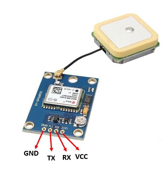
| GND | This is the ground pin that will be connected with the ground of the ESP32 board. |
| TX | This is the transmission pin used for serial communication. |
| RX | This is the receiver pin used for serial communication. |
| VCC | This is the VCC pin used to power up the GPS module. Connect it with the 3.3V of the ESP32 board |
SSD1306 0.96-inch OLED Display
Although there are several types of OLED displays available in the market the one which we will be using is the SSD1306 0.96-inch OLED display. The main component of all different types of OLED displays is an SSD1306 controller which uses I2C or SPI protocol to communicate with the microcontrollers. The OLED performs faster in SPI communication but it is popular with I2C communication. The reason for the popularity is the lower number of pins. The OLED displays can vary in size, colour, and shape but are primarily programmed in a similar way.
Let us take a look at the OLED display which we will be using in this article. It is called SSD 1306 0.96-inch OLED display which has 128×64 pixels and communicates only via I2C protocol with the ESP development boards. It is cheap and readily available in the market.
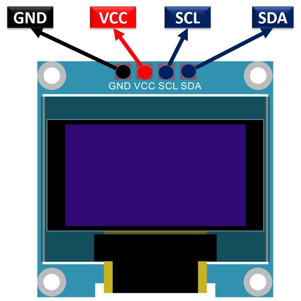
Pinout of OLED Display (I2C only)
Below you can see the pinout of this OLED Display.
ESP32 GPS Tracker Circuit Diagram
The OLED display has 4 terminals which we will connect with the ESP32 board. As the OLED display requires an operating voltage in the range of 3.3-5V hence we will connect the VCC terminal with 3.3V which will be in common with the ESP32 board. SCL of the display will be connected with the SCL pin of the module and the SDA of the display will be connected with the SDA of the module. By default, the I2C pin in ESP32 for SDA is GPIO21, and for SCL is GPIO22. The connections between the two devices can be seen in the table below.
| ESP32 board | SSD1306 OLED Display |
|---|---|
| VCC=3.3V | VCC |
| GPIO21(I2C SDA) | SDA |
| GPIO22(I2C SCL) | SCL |
| GND | GND |
Similarly, the NEO-6M GPS module also has 4 terminals which we will connect with the ESP32 board. As the GPS module requires an operating voltage in the range of 2.7-3.6V hence we will connect the VCC terminal with 3.3V which will be in common with the ESP32 board. The TX (transmitter) terminal of the GPS module will be connected with the RX2 pin of the ESP32 for communication. Likewise, the RX (receiver) terminal of the GPS module will be connected with the TX2 pin of the ESP32.
| ESP32 board | NEO-6M Module |
| VCC=3.3V | VCC |
| RX2 | TX |
| TX2 | RX |
| GND | GND |
All three devices will be commonly grounded.
The diagram below shows the schematic diagram of ESP32 with OLED display and NEO 6M Module.

Setting up Blynk Application for ESP32 Vehicle Tracker
To access vehicle location on our smart phones we will create a project in the Blynk app and link it with our Arduino sketch. Blynk is a free-to-use app where the user can build software to control microcontrollers such as Raspberry Pi, Arduino, and ESP8266 NodeMCU, etc. Follow the series of steps given below to successfully configure the application.
Installing and Getting Ready
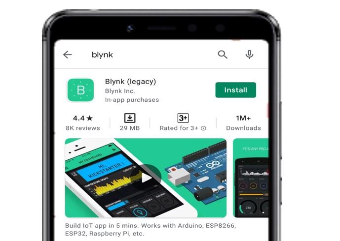
We will use an Android smartphone for this project. Go to Google Play or Apple Store (if using an iPhone).

Search for ‘Blynk’ and install the application.
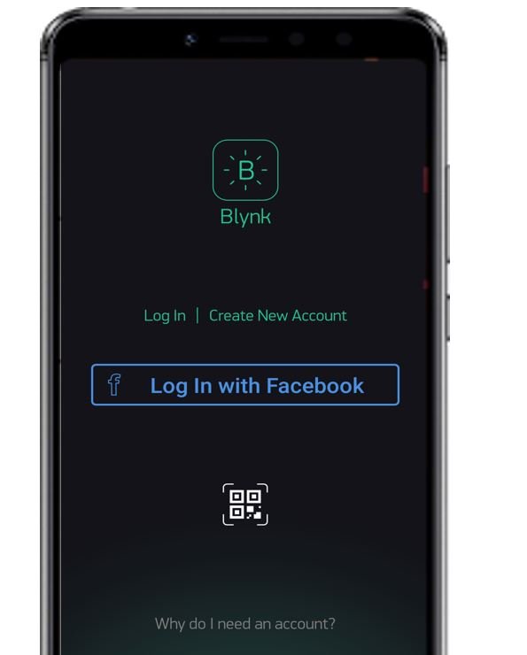
You will have to create an account to proceed further. You can also log in with your Facebook account if you possess that.
Creating Project
After you have successfully signed in the following window will appear. Click ‘New Project.’

Now specify the name of your project, device and connection type. After that press the ‘Create’ button.
You will receive a notification regarding your Authorization token. This can be accessed from the email account you signed in with and also through Project Settings.

Now the Blynk canvas will open. Press on the screen. The widget box will appear. Press the ‘Map’ widget. You can view information regarding it by pressing the icon present in the far right.
Now click on this widget and the map settings appear. Choose the virtual pin V0 as an input pin. Press ‘OK’.
These are the map settings which we are using.
After you alter the settings of the map the canvas will look something like this:
Installing Required Arduino Libraries
We will use Arduino IDE to program our ESP32 development board. Make sure your Arduino IDE already has the ESP32 plugin installed. To program our ESP32 board for this GPS tracker we will be required to install four libraries: BlynkSimpleEsp32.h, TinyGPS++.h, Adafruit_SSD1306.h and Adafruit_GFX.h
Installing Blynk Library
To use the Blynk app with our ESP32 board, we would have to install its library.
To download the library, click here. Click on ‘Code’ and then ‘Download Zip’.
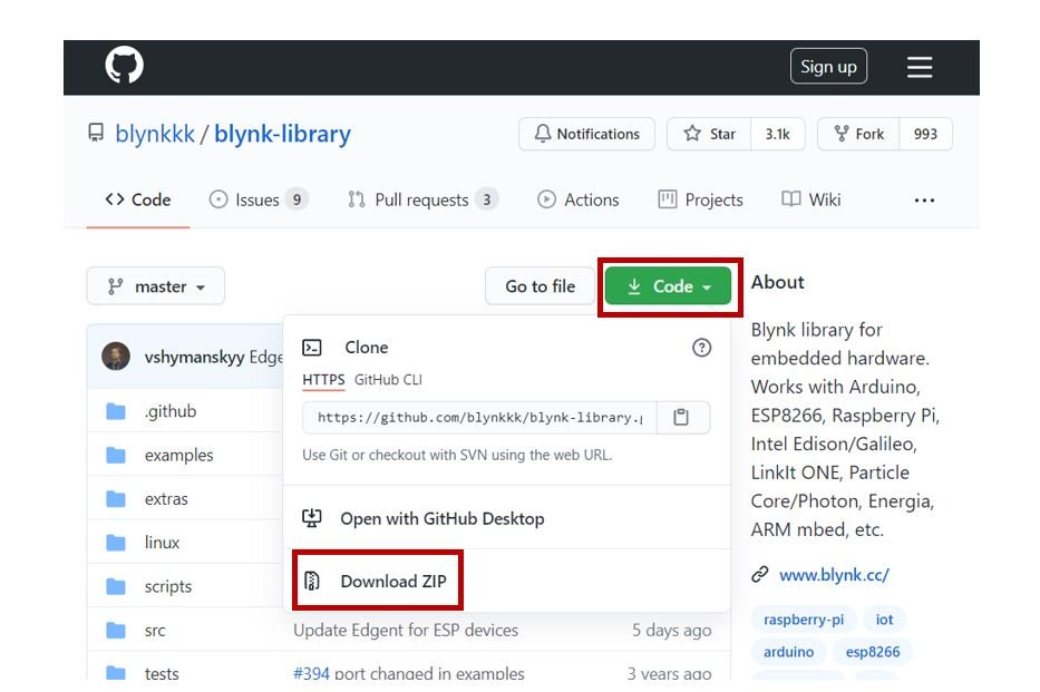
You have to go to Sketch > Include Library > Add .zip Library inside the IDE to add the library as well. After installation of the library, restart your IDE.
Installing TinyGPS++ Library
To make our project easier we will install the TinyGPS++ library to easily handle the receiving data from the GPS module. To download the library, click here. Click on ‘Code’ and then ‘Download Zip’.
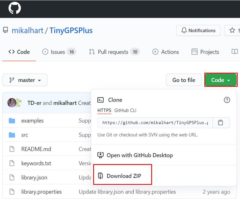
You have to go to Sketch > Include Library > Add .zip Library inside the IDE to add the library as well.
Installing OLED Display Libraries
To use the OLED display in our project, we have to install the Adafruit SSD 1306 library and Adafruit GFX library in Arduino IDE. Follow the steps below to successfully install them.
Open Arduino IDE and click on Sketch > Library > Manage Libraries
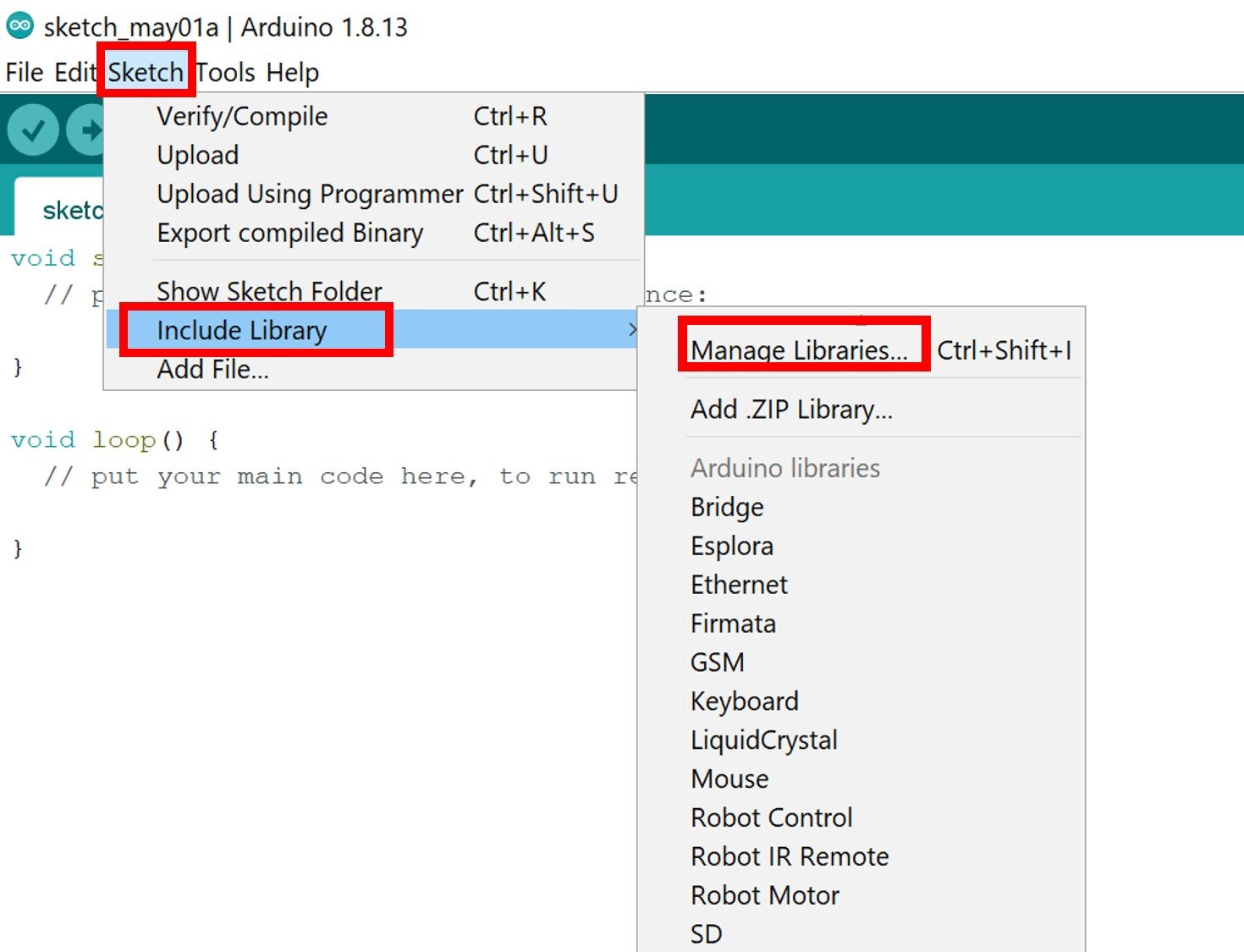
The following window will open up.

Type ‘SSD1306’ in the search tab and install the Adafruit SSD1306 OLED library.

We will also require the Adafruit GFX library which is a dependency for SSD1306. Type ‘Adafruit GFX’ in the search tab and install it as well.
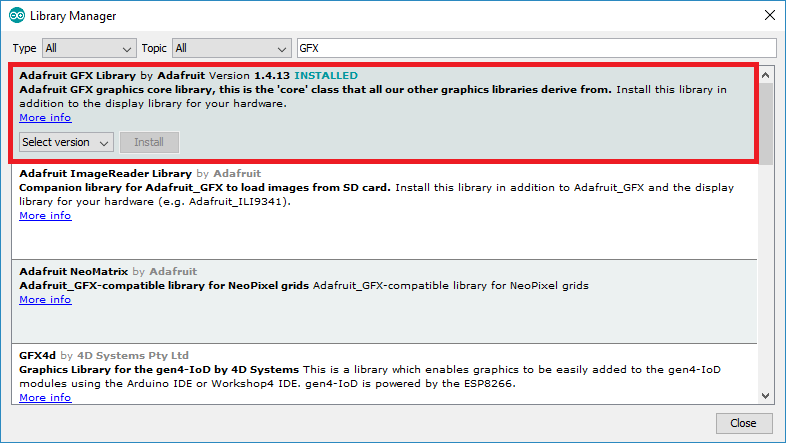
After installation of the libraries, restart your IDE.
Arduino Sketch ESP32 GPS Tracker
Open your Arduino IDE and go to File > New. A new file will open. Copy the code given below in that file and save it.
#include <TinyGPS++.h>
#include <HardwareSerial.h>
#include <WiFi.h>
#include <Wire.h>
#include <Adafruit_GFX.h>
#include <Adafruit_SSD1306.h>
#include <BlynkSimpleEsp32.h>

float latitude , longitude;
String  latitude_string , longitiude_string;

#define SCREEN_WIDTH 128
#define SCREEN_HEIGHT 64

Adafruit_SSD1306 display(SCREEN_WIDTH, SCREEN_HEIGHT, &Wire, -1);

const char *ssid =  "Your_SSID";
const char *pass =  "Your_Password";
char auth[] = "ec8EX0fnX1y78Oo6pO8lp8Of_AWUd***";

WidgetMap myMap(V0);
WiFiClient client;
TinyGPSPlus gps;
HardwareSerial SerialGPS(2);


void setup()
{
  Serial.begin(115200);
if(!display.begin(SSD1306_SWITCHCAPVCC, 0x3C)) {
    Serial.println(F("SSD1306 allocation failed"));
    for(;;);
  }

  WiFi.begin(ssid, pass);
  while (WiFi.status() != WL_CONNECTED)
  {
    delay(500);
    Serial.print(".");
  }
  Serial.println("");
  Serial.println("WiFi connected!");

  SerialGPS.begin(9600, SERIAL_8N1, 16, 17);
  Blynk.begin(auth, ssid, pass);
  Blynk.virtualWrite(V0, "clr");
}
void loop()
{
  while (SerialGPS.available() > 0) {
    if (gps.encode(SerialGPS.read()))
    {
      if (gps.location.isValid())
      {
        latitude = gps.location.lat();
        latitude_string = String(latitude , 6);
        longitude = gps.location.lng();
        longitiude_string = String(longitude , 6);
        Serial.print("Latitude = ");
        Serial.println(latitude_string);
        Serial.print("Longitude = ");
        Serial.println(longitiude_string);

  display.clearDisplay();
  display.setTextSize(1);
  display.setTextColor(WHITE);
  display.setCursor(0, 20);
  display.println("Latitude: ");
  display.setCursor(45, 20);
  display.print(latitude_string);
  display.setCursor(0, 40);
  display.print("Longitude: ");
  display.setCursor(45, 40);
  display.print(longitiude_string);

        Blynk.virtualWrite(V0, 1, latitude, longitude, "Location");
        display.display();
      }
     delay(1000);
     Serial.println();
    }
  }
  Blynk.run();
}
How the Code Works?
In this section let us see how the code works.
Including Libraries
Firstly, we will include all the following libraries which are required for this project. The WiFi.h and will be used to connect to the wireless network. The Wire.h will allow us to communicate through the I2C protocol. Whereas the other libraries are the ones which we previously installed and are required for the proper functionality of the OLED display, the GPS module and the Blynk application.
#include <TinyGPS++.h>
#include <HardwareSerial.h>
#include <WiFi.h>
#include <Wire.h>
#include <Adafruit_GFX.h>
#include <Adafruit_SSD1306.h>
#include <BlynkSimpleEsp32.h>
Defining OLED Display
We will first define the width and height of our OLED display in pixels. We are using a 128×64 display hence the width will be 128 and the height will be 64.
#define SCREEN_WIDTH 128
#define SCREEN_HEIGHT 64
Next, we will initialize the display by creating an object of Adafruit_SSD1306 and specifying the width, height, I2C instance (&Wire), and -1 as parameters inside it.’ -1′ specifies that the OLED display which we are using does not have a RESET pin. If you are using the RESET pin then specify the GPIO through which you are connecting it with your development board.
Adafruit_SSD1306 display(SCREEN_WIDTH, SCREEN_HEIGHT, &Wire, -1);Defining Variables
Next we will define some string and float variable that we will use later on in the code. These will save the latitude and longitude values of the vehicle.
float latitude , longitude;
String  latitude_string , longitiude_string;
Setting Network Credentials
Now, we need to define the SSID name and the password. Following lines set the name of SSID and password. You can replace the SSID and password to your own network credentials.
const char *ssid =  "Your_SSID";
const char *pass =  "Your_Password";
Defining Authorization key
We will define the authorization key which was emailed to us through Blynk in our account through which we logged in it. Keep this key safe with you for security concerns.
char auth[] = "ec8EX0fnX1y78Oo6pO8lp8Of_AWUd***"; Creating Instances
Create the following instances for the widget map, wifi client, TinyGPSPlus library and HardwareSerial.
WidgetMap myMap(V0);
WiFiClient client;
TinyGPSPlus gps;
HardwareSerial SerialGPS(2);
setup()
Inside the setup() function, we will open a serial connection at a baud rate of 115200.
Serial.begin(115200);Moreover, we will also initialize the OLED display by using display.begin(). Make sure you specify the correct address of your display. In our case, it is 0X3C.
if(!display.begin(SSD1306_SWITCHCAPVCC, 0x3C)) {
    Serial.println(F("SSD1306 allocation failed"));
    for(;;);
  }
The following section of code will connect our ESP32 board with the local network whose network credentials we already specified above. We will use the WiFi.begin() function. The arguments will be the SSID and the password which we defined earlier in the code. After a successful connection is established, “Connected to the WiFi network!” will get displayed on the serial monitor.
  WiFi.begin(ssid, pass);
  while (WiFi.status() != WL_CONNECTED)
  {
    delay(500);
    Serial.print(".");
  }
  Serial.println("");
  Serial.println("WiFi connected!");
Now, the GPS module and the Blynk appliation is also initialized.
  SerialGPS.begin(9600, SERIAL_8N1, 16, 17);
  Blynk.begin(auth, ssid, pass);
  Blynk.virtualWrite(V0, "clr");
loop()
Inside the loop() function, we will obtain data from the GPS module and check whether the location parameters are valid or not. If the parameters are valid then we save the values of longitude and latitude in their respective variables after converting them in readable format.
  while (SerialGPS.available() > 0) {
    if (gps.encode(SerialGPS.read()))
    {
      if (gps.location.isValid())
      {
        latitude = gps.location.lat();
        latitude_string = String(latitude , 6);
        longitude = gps.location.lng();
        longitiude_string = String(longitude , 6);
These values will get in the serial monitor.
Serial.print("Latitude = ");
Serial.println(latitude_string);
Serial.print("Longitude = ");
Serial.println(longitiude_string);
Additionally, we will display the location on the OLED display as well. This is done by the following lines of code.
First, we will clear the buffer by using clearDisplay() on the Adafruit_SSD1306 object. Next, we will control the colour of the text by using the setTextColor() function and passing WHITE as an argument. We will set the size of the text using setTextSize() and pass the size as a parameter inside it. We have set the font size as default which is 1.We will use the setCursor() function to denote the x and the y axis position from where the text should start. Then by using print() we will pass the text which we want to display on the OLED. We will set the cursor again at different positions to display the all the values correctly. We will call the display() function on the display object so that the text displays on the OLED.
  display.clearDisplay();
  display.setTextSize(1);
  display.setTextColor(WHITE);
  display.setCursor(0, 20);
  display.println("Latitude: ");
  display.setCursor(45, 20);
  display.print(latitude_string);
  display.setCursor(0, 40);
  display.print("Longitude: ");
  display.setCursor(45, 40);
  display.print(longitiude_string);
  display.display();
This GPS data is also sent to the Blynk application. The map will display the current position of the vehicle/person by accessing the latitude and longitude values.
Blynk.virtualWrite(V0, 1, latitude, longitude, "Location");Inside the loop function, we will use the Blynk.run() command to keep the connection running.
Blynk.run();Demonstration
Choose the correct board and COM port before uploading your code to the board.
Go to Tools > Board and select ESP32 Dev Module.

Next, go to Tools > Port and select the appropriate port through which your board is connected.

Click on the upload button to upload the code to your ESP32 development board.
After you have uploaded your code to the development board, press its ENABLE button.

Open your Blynk application. Open the project you created and press the ‘play’ button. You will be able to view your current location in the map.
The OLED display will also start displaying your location in latitude and longitude values.
To read more GPS related articles, follow the links below:
I am studying embedded systems. I do like your website as a beginner.
I like this project. But, this project needs a continuous WIFI connection, doesn’t it?
Yes, it requires. But you can use an LTE module instead to get internet connectivity.